The result of the added energy to the air flowing across the radiator tubes, emerging into a squeezing plenum through a 545 sq in radiator/intercooler face to a 118sq in opening - unquestionably generated a 'jet effect' of emerging flow of high temperature air.
Lednicer's model showed a net of 3% loss of available Hp (drag) (@.5M, 18000 feet) by assuming aft shutter exit temp of 170F degrees. Temp of coolant assumed at 212F. At 180 degree exit temp, the drag is zero. Above 180 there is net thrust.
Horkey agreed with you but all Performance calcs for high speed were assumed 'zero'.
The P-51H flight tests at 90" did achieve positive net thrust but coolant temps were in 240-250F range.
Here's a comparison of a very generic P-51 with the three engines according to their official ratings, in comparison to the performance target Pasoleati has set.
The flying weight I assumed was the P-51's historical maximum flying weight with full internal fuel and ammunition, which obviously isn't good for climb rate
(On the climb rate chart, the rectangle visualizes the area under the climb rate curve that reaches 6000 m in 6 min as required.)
As expected, the F21R is not going to be a good choice
In climb, the F20R comes out on top, though at MIL power, the F3R gets only overtaken in the last 500 m of the race to 6000 m.
In top speed, the F20R as espected holds a significant advantage at 6000 m.
In turn rate, for our 2000 m data point, F20R and F3R at WEP are surprisingly close, and I am a bit disappointed the low-altitude rated F21R doesn't do better.
The F21R probably only shines even at low altitudes if we use MIL instead of WEP, but that's just for speed and climb rate ... it hardly does anything for turn rate at 2000 m.
The flying weight I assumed was the P-51's historical maximum flying weight with full internal fuel and ammunition, which obviously isn't good for climb rate
(On the climb rate chart, the rectangle visualizes the area under the climb rate curve that reaches 6000 m in 6 min as required.)
Amazing stuff there
The P-51 for our rugged countries would've probably not be needing whole 180 gals of fuel? Even 120 gals makes it rangy engough unless some sort of escort job is required; 60 gals less = 360 gals less.
Or, go with the P-509 for a bit lower weight and size from the get go?
(the P-39 powered by the similar engines would've been lighter still)
Unfortunately, there was no such thing as a series-produced V-1710 with the 2-speed S/C, talk combination of the F20 and F21 :\
Or the one with variable-speed drive for the engine-stage S/C.
The P-51 for our rugged countries would've probably not be needing whole 180 gals of fuel? Even 120 gals makes it rangy engough unless some sort of escort job is required; 60 gals less = 360 gals less.
The specifications talk about a 500 km combat radius, so 180 gallons might not even be enough!
With 360 lbs less weight, the time to 6000 m reduces to 7.1 min according to my calculations, assuming WEP use.
I need to reduce weight to 7300 lbs to hit the 6 min to 6000 m point. That's in fact very close to the "first X73 iteration late April/early May 1940 projected at 7400 pounds" Bill mentioned here:
Unfortunately, there was no such thing as a series-produced V-1710 with the 2-speed S/C, talk combination of the F20 and F21 :\
Or the one with variable-speed drive for the engine-stage S/C.
You can estimate the impact of such a V-1710 variant by just combining the maximum from each graph. For example, start at sea level, "ride" the blue line up until it crosses the red line, then "ride" the red line to the ceiling, and you have the graph for a hypothetical two-speed V-1710 with the gear ratios of the F21R and the F20R. For the time to altitude graph, just mentally displace the red line so it intersects the blue line at the gear switch point, for example ca. 2500 m at MIL. That's a displacement by 1 min, so 6000 m will be reached at 8.6 min instead of 9.6 min.
For the variable-speed drive, just go from blue full throttle height to red full throttle height data points in a straight line. No easy trick for the time-to-altitude graph, but at least, you can see the area under the climb rate graph grow by the enclosed triangle.
Unfortunately, even a two-speed V-1710 cannot get us 6000 m in 6 min at this weight.
With 360 lbs less weight, the time to 6000 m reduces to 7.1 min according to my calculations, assuming WEP use.
I need to reduce weight to 7300 lbs to hit the 6 min to 6000 m point. That's in fact very close to the "first X73 iteration late April/early May 1940 projected at 7400 pounds" Bill mentioned here:
Dry weight of the R-2600-8 is given as 1986 lbs "without accessories". Relying on Dean's "America's Hundred Thousand", the data for the P-40F shows for the V-1650-1 "Engine: 1518 lbs" and "Cooling 294 lbs". Ignoring the rest of the engine-related categories as they're most likely not included in the R-2600-8 dry weight either, that gives us 1813 lbs for the V-1650-1 as "dry weight without accessories"-equivalent (though I figure "cooling" includes the coolant weight, as it's not listed anywhere else in that table), so we have a weight penalty of just 173 lbs or about 80 kg for the radial engine.
I've neglected propeller weight, which is 386 lbs on the V-1650-1, compared to 485.2 lbs for the F6F-3's propeller, which I presume is in the same ballpark as a suitable propeller for our R-2600-8. So, another 45 kg weight penalty for the R-2600-8 version of our fighter (total 125 kg).
Does anyone have an opinion on the relative weights of the four powerplant installations?
I was a bit surprised to see the above numbers on the V-1650-1 and the R-2600-8, which would come down to no more than 272 lbs extra weight for the radial engine.
I haven't compared the V-1710-81 to the V-1650-1 yet, but it seems the P-40F is the heaviest of all the P-40 variants for some reason.
With regard to radial engine drag, does the ca. 8% increase for the Fw 190 sound like it might be in the ballpark for a hypothetical radial-engined variant of the Mustang, too?
Were there any R-2600 engined fighters, and what propeller diameter did they use? From running the numbers, the propeller used on the Vultee Vengeance with its 12 ft 7 in diameter at some altitudes would be supersonic at fighter speeds, so they probably used smaller diameters?
Does anyone have an opinion on the relative weights of the four powerplant installations?
I was a bit surprised to see the above numbers on the V-1650-1 and the R-2600-8, which would come down to no more than 272 lbs extra weight for the radial engine.
That is despite the R-2600 being one of the heavier 14 cyl engines, with BMW 801 being the heaviest of the lot (thus, for the fighter installations, German V12s like DB 601/605 and Jumo 211 can save a lot of weight vs. the 801 and a good deal of drag, while sacrificing just a small % or power).
Japanese 14 cyl engines were much lighter (even the ones with good power), so was the Hercules and M-82.
170 lbs less, 1-stage 'normal' V-1710 F series vs. the 1650-1, or ~77 kg less.
Merlin 45 and similar 1-speed Merlins were in ballpark with these V-1710s.
With regard to radial engine drag, does the ca. 8% increase for the Fw 190 sound like it might be in the ballpark for a hypothetical radial-engined variant of the Mustang, too?
I'd add a bit more, 10% at least, since the radial Mustang gets rid of one of it's best aerodynamic advantages, namely the cooling system.
The suggested R-2800-powered Mustang was also to gain extra depth for the fuselage in order for the radial to fit well, height-wise. R-2600 was taller/wider still.
Were there any R-2600 engined fighters, and what propeller diameter did they use? From running the numbers, the propeller used on the Vultee Vengeance with its 12 ft 7 in diameter at some altitudes would be supersonic at fighter speeds, so they probably used smaller diameters?
170 lbs less, 1-stage 'normal' V-1710 F series vs. the 1650-1, or ~77 kg less.
Merlin 45 and similar 1-speed Merlins were in ballpark with these V-1710s.
I suspect that propeller was optimized for something else than speed
There's a Beaufighter test on Mike's site that mentions that when the Hercules VI's WEP was uprated from 2800 rpm to 2900 rpm, using that setting actually decreased top speed a little, so it was questionable whether it was worth it. I'm pretty sure that was evidence of propeller efficiency going down when tip Mach number was going up!
There's a Beaufighter test on Mike's site that mentions that when the Hercules VI's WEP was uprated from 2800 rpm to 2900 rpm, using that setting actually decreased top speed a little, so it was questionable whether it was worth it. I'm pretty sure that was evidence of propeller efficiency going down when tip Mach number was going up!
There's a Beaufighter test on Mike's site that mentions that when the Hercules VI's WEP was uprated from 2800 rpm to 2900 rpm, using that setting actually decreased top speed a little, so it was questionable whether it was worth it. I'm pretty sure that was evidence of propeller efficiency going down when tip Mach number was going up!
Engines were having their reduction ratio changes during the ww2, and a lot of them ended up with better props as the war dragged on. A 4-bladed prop on a 1500-1700 HP engine paddle-blade prop will not be out of it's place.
Engines were having their reduction ratio changes during the ww2, and a lot of them ended up with better props as the war dragged on. A 4-bladed prop on a 1500-1700 HP engine paddle-blade prop will not be out of it's place.
The propeller diameters I use on the Mustang (derivative):
- F20R: 10' 9" = 3.28 m
- V-1650-1: 11' = 3.35 m
- Hercules VI: 12' 9" = 3.89 m
- R-2600-13: 12' = 3.66 m
That yields the following Mach numbers in top speed level flight (which are based on some preliminary calculations I've done zsubg some of the assumptions we made in this thread):
Basically, over Mach 0.9, efficiency is likely to degrade, and at Mach 1.0, it's probably bad.
Admittedly, historically some US fighters used very large propellers, and I've always wondered about these ... if you know of any NACA report dealing with these, that might be helpful. I've checked a few, which left me with no clear picture.
Here's a Standard Aircraft Characteristics sheet for the F6F-5 which I suspect shows the effect.
Note that curve 2, which according to the SAC is Combat power at 2700 rpm, drops in speed below the curve 3, which according to the SAC is MIL, above 22000 ft. (Actually, it drops to equality and is not actually drown where it would be lower, but you see the trend.)
Here the documentation gets inconsistent as on the SAC, MIL is indicated with 2700 rpm too, in which case the curve would make no sense, as the engine would be in just the same condition, 2700 rpm, throttle wide open, regardless of whether the pilot put the throttle lever in the Combat or in the MIL position ... the supercharger just doesn't provide enough boost above full throttle height.
However, there's also the attached SEFC that is not part of the SAC, which shows that MIL is supposed to be run at 2550 rpm only in high supercharger gear. That would seem like an explanation for curve 3, and the physical reason for the engine running at a lower power output and yet the F6F being faster most likely is that propeller efficiency drops quite dramatically at 2700 rpm.
So a reduction in power yields a gain of about 15 knots top speed at 24000 ft in this case. That's pretty significant.
Does the XP-51B not fit within scope. It was modified prodution P-51-NA with 1650-3 first flight November 30th.
As to radial engines on a P-51 airframe? Not only much higher drag but reduced exhaust thrust and eliminated Meredith effect offset to cooling drag.
FWIIW the original FW 190 drag data mght serve for the fuselage/cockpit/empennage approximation but IMO, that is not a good solution for a Mustang airframe.
(...) and the physical reason for the engine running at a lower power output and yet the F6F being faster most likely is that propeller efficiency drops quite dramatically at 2700 rpm.
So a reduction in power yields a gain of about 15 knots top speed at 24000 ft in this case. That's pretty significant.
Remember that the engine RPM may be physically lower, but you're pulling more pitch on the prop to do so. Props taking a bigger biter of the air, so they travel farther forward for each revolution.
Good point, it does. I'd expect the 20s-series Merlin than the Merlin 61 (which I think is the equivalent to the V-1650-3) would be better in the context of Pasoleati's specification due to being lighter, with the climb and turn rate requirements being the hardest to meet, so I've ignored it until now, but it probably deserves a closer look.
Unfortunately, not all pages of the original report are included the file (I'd have loved to see the missing propeller efficiency chart),
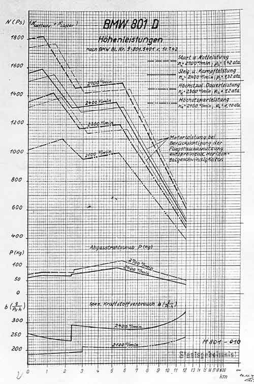
With regard to exhaust thrust, would you really expect this to be markedly lower with the radial engines if we assume we'll be using individual exhaust jet nozzles? Here's a BMW 801 chart showing quite a useful amount of exhaust thrust, and that's with some of the lower stacks combined, so there would be potential for a bit more.
Remember that the engine RPM may be physically lower, but you're pulling more pitch on the prop to do so. Props taking a bigger biter of the air, so they travel farther forward for each revolution.
Could you please elaborate what you mean by "bigger bite"? I'd think that the pitch adjustment would result in a very similar product of air mass accelerated, and amount of air mass accelerated, for the same power under not-too-different propeller rpms. That would be equivalent to very similar thrust, independend of the rpm/pitch combination (as long as we keep the variations within limits, of course).
Could you please elaborate what you mean by "bigger bite"? I'd think that the pitch adjustment would result in a very similar product of air mass accelerated, and amount of air mass accelerated, for the same power under not-too-different propeller rpms. That would be equivalent to very similar thrust, independend of the rpm/pitch combination (as long as we keep the variations within limits, of course).
With a constant speed prop, as you pull the RPM control back to reduce RPM, prop pitch increases so that the prop travels farther forward with each revolution.
Max RPM, example on takeoff, means the prop is taking the least amount of distance forward per revolution.
(greatly simplified, this is ignoring prop slip, etc)
Good point, it does. I'd expect the 20s-series Merlin than the Merlin 61 (which I think is the equivalent to the V-1650-3) would be better in the context of Pasoleati's specification due to being lighter, with the climb and turn rate requirements being the hardest to meet, so I've ignored it until now, but it probably deserves a closer look.
Unfortunately, not all pages of the original report are included the file (I'd have loved to see the missing propeller efficiency chart),
With regard to exhaust thrust, would you really expect this to be markedly lower with the radial engines if we assume we'll be using individual exhaust jet nozzles? Here's a BMW 801 chart showing quite a useful amount of exhaust thrust, and that's with some of the lower stacks combined, so there would be potential for a bit more.
Hi Henning - I just looked at the CA-15 report, section 5, and confess to some skepticism. The drag alues in the table are implied North American values for XP-51G at 100 fps.
AFAIK the published Performance drag tables for the P-51B, D and H were recorded at Re=1.84x10^6 for 1/4 scale P-51B, Re=2.0x10^6 for 1/4scale P-51D, and Re=9.0x10^6 for 1/4 scale P-51H. That translates to 119mph, 129mph and 234mph repecively.
The CAC-15 tables reference total drag in pounds based on 100 fps, or 68mph.
Calculating CDP1 wing for drag force of 15 pounds for wing looks like ;
15/QS= CDP1wing.
QS for SL and 68mph = .5 rho x (100)^2 x 235 = 2785. 15/2785= 0.00540. This is correct value at CD (Re) for Re=2.0x10^6
However, while 0.00540 corresponds to Re=2.0x10^6 in the CD vs Re Chart for the NACA 66,2 -18155 wing, V =128mph and 188fps - not 100fps.
68mph and 100fps corresponds to RE=1.66x10^6 for P-51G/H wing at SL for 1/4scale model.
I might not be thinking at a rational level after watching the Cowboys tank (again) but something is 'off'.
But Re=2x10^6 correlates to 119mph (175fps) --------> Q=36.3; S=235; QS=8530.5; D=CDP1 (QS); D=
The NACA Langley Test of production P-51B-1 had Re=6.19x10^6 which is ~ 100mph
The CDp of both the B and D are the same at 119mph, namely 0.0070 at 2.0x10^6 Re
The wings of the P-51F/G/H/J are the same, and the NACA 66 series had a CDp1 of 0.0450 at 2.0x10^6 Re
Does anyone have the cited source "S.J. Worth, R.T.O and B.A.C. at NAA" document or report?
Hi Henning - I just looked at the CA-15 report, section 5, and confess to some skepticism. The drag alues in the table are implied North American values for XP-51G at 100 fps.
The comparison at 100 fps thing seems to be something very British - I've seen similar drag item lists for the Spitfire, and I think Mike even has one up on his site for the Meteor vs the German jets - unfortunately, no explanation there either: http://www.wwiiaircraftperformance.org/me262/RAE-german-jets.pdf
It seems that rather than using wind tunnel data, the CAC used performance measurements as the basis of their drag table:
"From performance figures quoted in a report by S.J. Worth, R.T.O., B.A.C., at N.A.A. on the P51-G, the extra-to-induced drag has been estimated using the same propeller efficiencies as shown on page 14, of this report for three flight conditions. The highest of the three drag values obtained is used as a basis for the CA-15 drag estimate.
For the P51-G the drag of all items with the exception of the fuselage, could be fairly accurately estimated giving the fuselage drag by difference from the assumed total.
The corresponding drag values for the CA-15 were obtained by comparing the wetted and frontal areas."
It occurred to me that I had recently seen a NACA report on an ejector exhaust system designed to improve cooling of an R-2800 installation, and checking it out, it actually has a (calculated) figure for exhaust thrust for comparison purposes ...
My coarse rule of thumb is that you get about 0.5 N/kW exhaust thrust using individual jet exhausts (as assumed in the below NACA report), and about half that for collector rings with rear-facing exhaust.
That would come out as 122 lb(f) for the NACA example, compared to their calculated 162 lb(f) - not bad for such a simple rule.
They do actually provide the way they calculated exhaust thrust:
(Dash)Ve = mean effective exhaust velocity
Me = exhaust mass flow rate
g = acceleration of gravity
R = gas constant for exhaust gas
Te = exhaust gas temperature
p0 = free stream static pressure
A = exhaust nozzle or exhaust nozzle tail pipe area
(Hooker's "Performance of a Supercharged Aero Engine" actually has a very complete method of calculating exhaust thrust and shaft power losses due to back pressure, but somehow I couldn't make that work for me.)
With a constant speed prop, as you pull the RPM control back to reduce RPM, prop pitch increases so that the prop travels farther forward with each revolution.
Max RPM, example on takeoff, means the prop is taking the least amount of distance forward per revolution.
(greatly simplified, this is ignoring prop slip, etc)
As long as the propeller efficiency at different advance ratios is the same, that should not change anthing, if I understand it correctly.
With a constant speed propeller, one is operating on a different efficiency-over-advance ratio curve at both engine speeds, one can't assume one is working with a single, sloped efficiency curve like one would with a fixed-pitch propeller.
But what you will find if you start flying planes with a constant speed prop is that maximum speed is not found at max engine RPM, but backed off a couple hundred RPM as the blade pitch increases. Then if you keep increasing blade pitch and lowering engine RPM your speed goes down until you get to the best cruise RPM.
The comparison at 100 fps thing seems to be something very British - I've seen similar drag item lists for the Spitfire, and I think Mike even has one up on his site for the Meteor vs the German jets - unfortunately, no explanation there either: http://www.wwiiaircraftperformance.org/me262/RAE-german-jets.pdf
It seems that rather than using wind tunnel data, the CAC used performance measurements as the basis of their drag table:
That sounds a bit like the Me 109 example from Hoerner's book, though I have no idea how the 100 fps enter the picture.
As "performance figures" are specifically mentioned, that doesn't sound like they used actual wind tunnel data from NAA.
I think I get the rationale for 100fps. Simplifies calc for drag in # if you have the actual parasite drag from 68mph freestream velocity. But I have never seen the base drag numbers in RAF reports that cite the respectve MAC and Re.
But what you will find if you start flying planes with a constant speed prop is that maximum speed is not found at max engine RPM, but backed off a couple hundred RPM as the blade pitch increases. Then if you keep increasing blade pitch and lowering engine RPM your speed goes down until you get to the best cruise RPM.
General aviation aircraft with direct-drive engines often are capable of getting their propeller tips into the transonic range, so that might actually be just what I've described.
For WW2 fighter aircraft, we have plenty of performance measurements that show that in the vast majority of cases, top speed is reached at maximum engine speed.
- The 15° pitch curve peaks at at an efficiency of 0.78 for an advance ratio of 0.64.
- The 20° pitch curve peaks at an efficiency of 0.83 for an advance ratio of 0.85.
So if you reach a top speed at 20° pitch, for example using 2200 rpm and 1000 HP, you have available 850 HP of thrust power.
Now increase your engine speed to 2920 rpm to get to an advance ratio of 0.85 at the same flight speed. Your efficiency decreases to 0.78, but at the increased rpm, your power also increases - roughly linearly with engine speed. So now your engine is delivering 1330 HP, which even at the decreased efficiency of 0.78 still yields 1040 HP of thrust power.
That's just to illustrate that there's no general rule that makes lower rpm more effective automatically - it all depends on the slopes of the family of efficiency curves. These slopes drop steeper when a propeller experiences compressilibity effects, and I suspect that is what some of the less typical WW2 performance curves might be showing.
Reading this thread and a couple of other things have got me wondering about the CAC Mustangs and possible plans that CAC and NAA had for them (including possible P-51H or even P-82 Twin Mustang production, but those are kind of "what ifs" on their own). But to go along with this thread, is some of the stuff talked about in this thread (relatively rugged, relatively easy to mass produce, high performance fighter) a factor in why CAC bought a license to build P-51s? Not to mention in the future they did still have a tech transfer agreement with NAA that allowed them to build the CAC Avon Sabre.
Note that curve 2, which according to the SAC is Combat power at 2700 rpm, drops in speed below the curve 3, which according to the SAC is MIL, above 22000 ft. (Actually, it drops to equality and is not actually drown where it would be lower, but you see the trend.)
The F6F-3's SAC show the same kind of curves as the F6F-5's, but they contain one remark regarding the engine ratings I don't quite understand:
"Engine ratings are AEL ratings. These ratings do not conform to engine data obtained from F6F flight test. The flight test data are used in performance calculations."
"AEL" is an acronym that evades me ... the only vaguely matching term I found was "Aircraft Equipement List", but I don't have much confidence in that!
The AEL ratings are listed on page 1 of the SAC for COMBAT, MILIATRY, NORMAL and TAKE-OFF power, and another set of ratings under the same headlines is listed on page 5, where they are captioned "Rammed engine ratings for performance from flight test clean condition".
The trend seems to be that the "flight test data" shows about 3000 ft higher (critical) altitudes for the MIL ratings, but about 1000 ft lower ones for the COMBAT rating.
Has anyone seen this kind of differentiation by "AEL"and "flight test data" ratings before?
General guidelines are 10-12 degrees for taildraggers, if it is lower than that stability on the ground suffers. I don't think there are many taildraggers at just 8 degrees.
Since I just came across it in Dan Sharp's "Secret Projects of the Luftwaffe", here's a data point for the Fw 191: It has a ground angle of 9.5 degrees.
It seems it was supposed to have a special type of high-lift device that doubled as dive brake, called Multhopp flap after its inventor, but I haven't been able to find any details on this yet.
... It seems it was supposed to have a special type of high-lift device that doubled as dive brake, called Multhopp flap after its inventor, but I haven't been able to find any details on this yet...
Yes, that's how I 'read' it too. It looks as though the forward three-quarters of the underside slides backwards on a track, allowing that angling down while also providing a slot. Sounds good but obviously Hans Maulthopp wasn't able to make the structure rigid enough to avoid fluttering on the Fw 191.
This site uses cookies to help personalise content, tailor your experience and to keep you logged in if you register.
By continuing to use this site, you are consenting to our use of cookies.

")