Does anyone have better versions of the following D-188A precursors? (Sorry about the orientation of the first one - my Mac conspires to revert to the original orientation of the scan in some cases even though it's depicted correctly in the file.)

You are using an out of date browser. It may not display this or other websites correctly.
You should upgrade or use an alternative browser.
You should upgrade or use an alternative browser.
Bell D-139 "Vertiburner" VTOL jet fighters - precursors to the D-188A
- Thread starter Tailspin Turtle
- Start date
Tailspin Turtle said:Does anyone have better versions of the following D-188A precursors?
Why... yes. Since APR issue V2N3 will have part one of the D-188 article, I happen to have these to hand. The full-rez images (and many more) will appear in that issue.
Attachments
Tailspin Turtle said:The "Vertiburner" was probably the D-139. I've seen conflicting reports of the configuration of the D-188.
The Vertiburner system on the D-139 appears to have turned out to have been about as successful as the augmentor wing on the XFV-12 or the augmented thrust on the original XV-4 Hummingbird. Consequently, Bell took the basic design back to the board, yanked out the Vertiburner and repalced it with dedicated conventional lift jets and called it the D-188. How they got from the D-188 to the D-188A, I've no idea.
I'd sure love to see more on the D-2001 and the D-2021B. Look to be either research planes, or ground attackers. But this is all I have.
Attachments
I wouldn't mind doing a Bell D-139 if I had access to the appropriate references. That Convair/Bell F-109 looks pretty awesome too.
Thanks - that's the Bell D139 Vertiburner. Other Bell VTOL jets here:
http://www.secretprojects.co.uk/forum/index.php/topic,1139.0.html
http://www.secretprojects.co.uk/forum/index.php/topic,1139.0.html
Attachments

blackkite
Don't laugh, don't cry, don't even curse, but.....
- Joined
- 31 May 2007
- Messages
- 8,819
- Reaction score
- 7,718
Hi! Vertiburner patent.
"In the drawings:
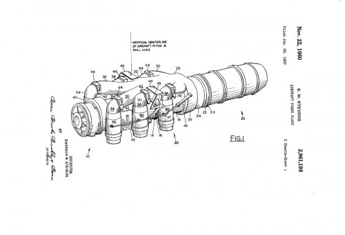
Fig. 1 is a top and side elevational perspective View of a power plant embodying an aircraft engine arrangement of the present invention;
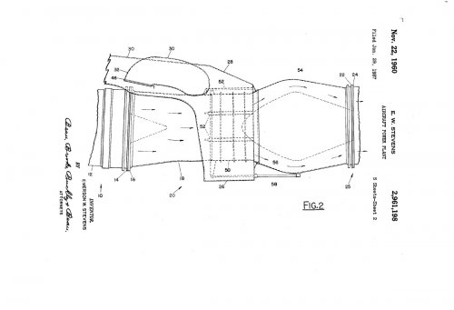
Fig. 2 is a fragmentary side elevational view of a portion of the engine of the invention showing the diversion control valve set in position for delivery of the engine turbine discharge gas to the usual afterburner arrangement for horizontal thrust;
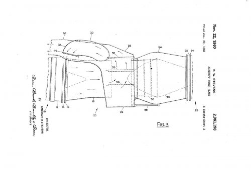
Fig. 3 is a view corresponding to Fig. 2, but showing the valve set to divert turbine discharge gas to the vertically swingable afterburner components of the engine;
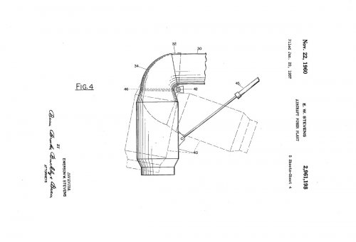
Fig. 4 is a fragmentary elevational view through one of the auxiliary afterburner thrust chamber devices and showing its swing control mechanism, the thrust chamber being illustrated in its variously adjustable positions to direct the thrust outputs thereof between vertical and substantially horizontal directions; and
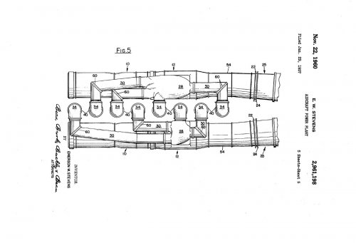
Fig. 5 is a plan view of a novel multi-jet engine arrangement of the invention, centering the overall thrust output in the vertical longitudinal plane of the aircraft, in improved manner.
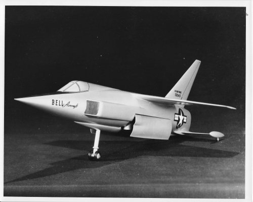
Vertiburner applied design.
Landing gear was located fuselage nose and wing tip of horizontal tail stabilizer.
Three side view source by Scott-san's excellent work!!
"In the drawings:
Fig. 1 is a top and side elevational perspective View of a power plant embodying an aircraft engine arrangement of the present invention;
Fig. 2 is a fragmentary side elevational view of a portion of the engine of the invention showing the diversion control valve set in position for delivery of the engine turbine discharge gas to the usual afterburner arrangement for horizontal thrust;
Fig. 3 is a view corresponding to Fig. 2, but showing the valve set to divert turbine discharge gas to the vertically swingable afterburner components of the engine;
Fig. 4 is a fragmentary elevational view through one of the auxiliary afterburner thrust chamber devices and showing its swing control mechanism, the thrust chamber being illustrated in its variously adjustable positions to direct the thrust outputs thereof between vertical and substantially horizontal directions; and
Fig. 5 is a plan view of a novel multi-jet engine arrangement of the invention, centering the overall thrust output in the vertical longitudinal plane of the aircraft, in improved manner.
Vertiburner applied design.
Landing gear was located fuselage nose and wing tip of horizontal tail stabilizer.
Three side view source by Scott-san's excellent work!!
Attachments
blackkite
Don't laugh, don't cry, don't even curse, but.....
- Joined
- 31 May 2007
- Messages
- 8,819
- Reaction score
- 7,718
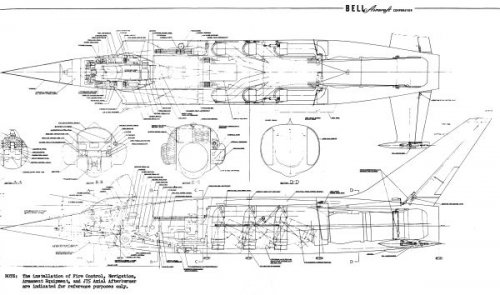
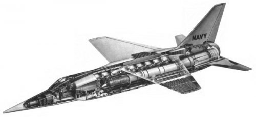
This design shows another concept. D-188? Fuselage main engine concept is same as D-188A.
D-188 main engine seems to be J79 and lift engine seems to be J85.
Perhaps Bell wanted to decrease D-188 lift engine dead weight by D-188A design.
Perhaps D-188 level flight engines are two J79s and VTOL engines are two J79s and nine J85s. Dead weight in level flight are nine J85s.
D-188A level flight engines are six J85s and VTOL engines are eight J85s. D-188A design does not need two J79 engines. Dead weight in level flight are only two J85s.

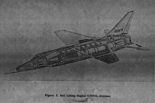
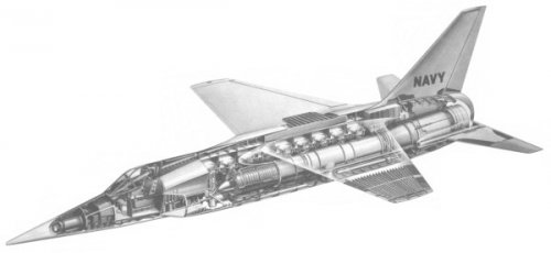
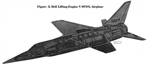
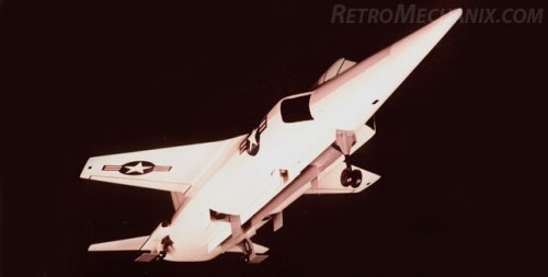
You can see nine lift engine exhaust nozzle long door at the center bottom of the fuselage and two main engine exhaust nozzle door at the side bottom middle of the fuselage when vertical flying mode in the second picture. Perhaps lift engines air intakes are located side of the fuselage, because if lift engines air intakes are located upper side of the fuselage, intake air push fuselage to downward same as XFV-12.
Aft landing gear and after burner air intake are located wing root of the horizontal tail stabilizer.
You can see nine lift engines located fuselage center line in bottom picture.
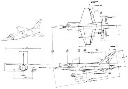
D-188A.
D-188 main engine seems to be J79 and lift engine seems to be J85.
Perhaps Bell wanted to decrease D-188 lift engine dead weight by D-188A design.
Perhaps D-188 level flight engines are two J79s and VTOL engines are two J79s and nine J85s. Dead weight in level flight are nine J85s.
D-188A level flight engines are six J85s and VTOL engines are eight J85s. D-188A design does not need two J79 engines. Dead weight in level flight are only two J85s.
Bell D188 Jet VTOL Fighter for the USN (1956) - Luftwaffe and Allied Air Forces Discussion Forum
Bell D188 Jet VTOL Fighter for the USN (1956) Post-WW2 Military and Naval Aviation
forum.12oclockhigh.net
You can see nine lift engine exhaust nozzle long door at the center bottom of the fuselage and two main engine exhaust nozzle door at the side bottom middle of the fuselage when vertical flying mode in the second picture. Perhaps lift engines air intakes are located side of the fuselage, because if lift engines air intakes are located upper side of the fuselage, intake air push fuselage to downward same as XFV-12.
Aft landing gear and after burner air intake are located wing root of the horizontal tail stabilizer.
You can see nine lift engines located fuselage center line in bottom picture.
D-188A.
Attachments
Last edited by a moderator:
blackkite
Don't laugh, don't cry, don't even curse, but.....
- Joined
- 31 May 2007
- Messages
- 8,819
- Reaction score
- 7,718
Re: Bell D,139 project
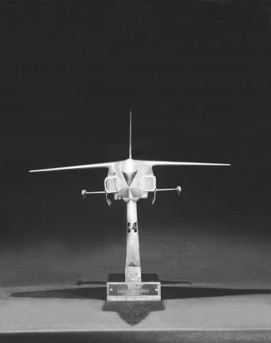
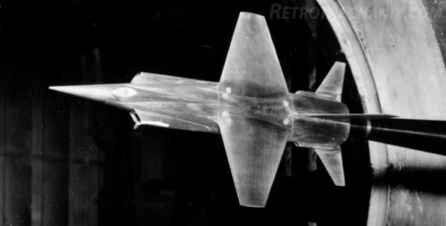
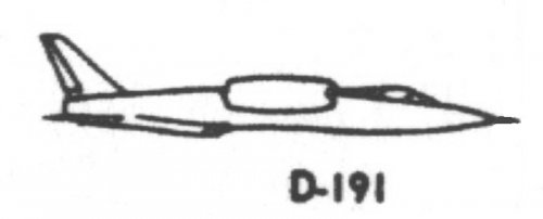
Low wing, shock cone type air inlet, twin engine and tall vertical tail stabilizer with middle position horizontal tail stabilizer. Tailed double delta wing.
Fuselage bottom looks like space shuttle. Twin engine with vertiburner design?
Very rare picture!!
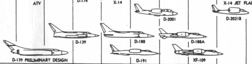
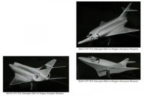
D-191 is a mysterious project. Any information?
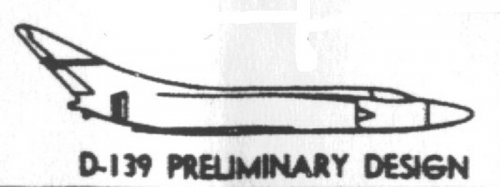
D-139 preliminary design : two propulsion engines with vertiburners?
D-139 : one propulsion engine with six vertiburners
D-188 : two propulsion/lift engines+nine lift engines
D-188A : six propulsion/lift engines+two lift engines
Perhaps every propulsion engine have after burner.
I believe this project is D-139 preliminary design which is included in Scott-san's chart.ivran said:Any information, or drawing of this project?
Nice design but only small pictures, maybe 3 view?
Simply aerodynamic line, but superb performance
Low wing, shock cone type air inlet, twin engine and tall vertical tail stabilizer with middle position horizontal tail stabilizer. Tailed double delta wing.
Fuselage bottom looks like space shuttle. Twin engine with vertiburner design?
Very rare picture!!
D-191 is a mysterious project. Any information?
D-139 preliminary design : two propulsion engines with vertiburners?
D-139 : one propulsion engine with six vertiburners
D-188 : two propulsion/lift engines+nine lift engines
D-188A : six propulsion/lift engines+two lift engines
Perhaps every propulsion engine have after burner.
Attachments
- Joined
- 27 December 2005
- Messages
- 17,752
- Reaction score
- 26,450
I would now like to turn to more sophisticated aircraft . Dating all the way back to 1953, we have continuously examined the problem of the V /STOL fighter bomber , and we wanted to put these photographs on the record since it does indicate that much of the present European efforts are really extensions of work that were started in this country and not followed through.
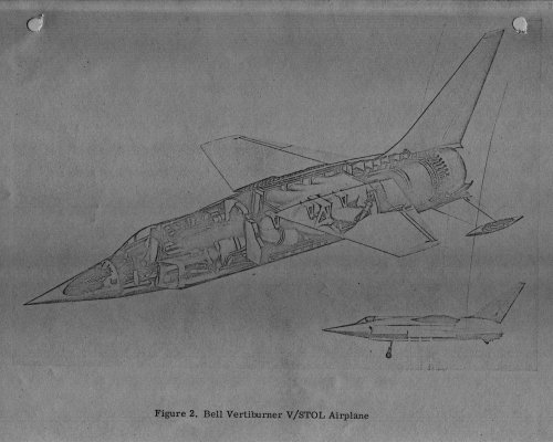
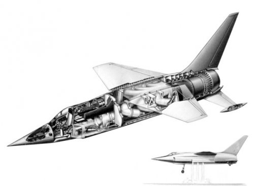
This is a single engine V /STOL airplane with vectoring thrust nozzles which also included burning in those thrust nozzles. This was called the vertiburner concept. We used a J-75 engine . It was a supersonic airplane, and was supported by Air Force study contracts It was decided not to continue with development of these vertiburners in this country. However, the British did go ahead with the support of U.S. funds, to develop the Bristol Pegasus- 5 engine, with which I am sure you are all familiar. It is being used in the P - 1127 airplane.
The P-1127 has demonstrated that Bell's approach to V /STOL in 1953 was a proper one, and further, that the British-Siddeley engine and their concept of burning in these nozzles, would justify the vertiburner approach which we studied . We, however, turned our back on a single -engine airplane and started to look at a minimum of two propelling engines to give the pilots the safety of dual engines in level flight.
To accomplish this we utilized the J- 85 in about 1956, and investigated a lifting engine V/STOL concept. Here we had nine J -85's mounted on the centerline of the airplane, two J -79's with thrust diverters to propel the airplane in level flight. Now, this is amazingly like the present Dassault proach to the problem and some of the German approaches with lifting engines.
We examined this airplane in very great design detail and proposed it to the Navy for their deck-ready interceptor V/STOL competition . It came to a gross weight of about 38,000 to 40,000 pounds. At that point we decided that instead of just carrying these lift engines around as deadweight, we would try to use them both in the lifting and propelling modes. So we stepped away from this lifting engine approach similar to the Balzac and the Mirage III V, to the D - 188 / XF - 109 concept. This was salable to the Navy.
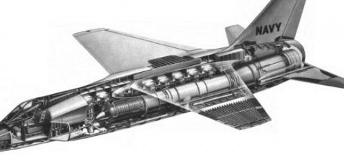
In order to accomplish same deck -ready intercept mission we found that this new placement of engines reduced our gross weight by some thing like 18,000 pounds. It was a more efficient approach to V /STOL. The Navy started the program . The Air Force became interested and started matching funding, so that the airplane could also accplish a fighter- bomber role. Out of this effort came the Air Force designation XF - 109. This airplane, therefore, grew a little bit in order to do both missions. We had to let the gross weight then grow back up to about 30,000 pounds. A 30,000- pound airplane powered with eight J-85's, two engines behind the pilot's cockpit , two on each of the wing tips, and two in the after fuselage, gave us not only a much more efficient V/STOL, but also a positive ground effect and a good landing capability. It opened up our whole fuselage for cargo, bomb load, and fuel, and it let us make an approach on a full weapon system basis to the combined services requirements for an aircraft.
Now, we started this in about 1957, and we worked through until - say , 1957 through to about 1959. We did a tremendous amount of work in that time period. We completed all of our drawings up to the point at which the next step would have been to start hardware in the shop . This is very much of an engineering mockup. All of the parts are duplicated and reproduced ; the systems are all completely laid out in this aircraft. We have a film which indicates this to some degree.
William G. Gisel, president of Bell Aero Systems, 1963 Hearings to Congress.
Hearings
www.google.co.nz
- Joined
- 27 December 2005
- Messages
- 17,752
- Reaction score
- 26,450
- Joined
- 26 May 2006
- Messages
- 34,917
- Reaction score
- 15,790
Does anyone have better versions of the following D-188A precursors? (Sorry about the orientation of the first one - my Mac conspires to revert to the original orientation of the scan in some cases even though it's depicted correctly in the file.)
My dear Tailspin,
in AIAA,the D-118 was a two-seat convertiplane project,intended to be
an observation and reconnaissance aircraft,powered by single engine,how
come it's here a fighter ?.
- Joined
- 6 November 2010
- Messages
- 5,263
- Reaction score
- 5,517
A more precise source than 'AIAA' would be welcome.My dear Tailspin,
in AIAA,the D-118 was a two-seat convertiplane [...]
- Joined
- 26 May 2006
- Messages
- 34,917
- Reaction score
- 15,790
A more precise source than 'AIAA' would be welcome.
I don't know more than AIAA.
- Joined
- 26 May 2006
- Messages
- 34,917
- Reaction score
- 15,790
My dear Tailspin,
in AIAA,the D-118 was a two-seat convertiplane project,intended to be
an observation and reconnaissance aircraft,powered by single engine,how
come it's here a fighter ?.
From vstol.org
Attachments

- Joined
- 27 December 2005
- Messages
- 17,752
- Reaction score
- 26,450
The only reference to D-118 comes in filenames, maybe a typo for D-188.
eAPR issue V2N3 has an excellent article on the D-139/D-188 Vertiburner, there's no D-118 designations mentioned there.
I fixed up image links in the topic.
eAPR issue V2N3 has an excellent article on the D-139/D-188 Vertiburner, there's no D-118 designations mentioned there.
I fixed up image links in the topic.
Last edited:
- Joined
- 27 December 2005
- Messages
- 17,752
- Reaction score
- 26,450
Some reports which seem relevant to topic in sources for https://apps.dtic.mil/sti/tr/pdf/AD0102024.pdf
Marquardt Aircraft Company Proposal No 834 "Development of Model MA35 Vertiburner for Bell VTOL Airplane". July 1954
Bell Aircraft Corporation "VTOL Day Fighter Weapon System, Summary Report", Bell Aircraft Corporation Report No. D139-945-027, July 27, 1954
O'Malley, J, A, Zabinsky, J. et. al "VTOL Dayfighter Weapon System - Aerodynamic Data", Bell Aircraft Corporation Report No. D139-945-028, July 15, 1954
Bell Aircraft Corporation "VTOL Dayfighter Weapon System - Structural and Weight Data", Bell Aircraft Corporation Report- No. D139-945-029, July 1954
Bell Aircraft Corporation. "Technical Summary Report", Bell Aircraft Corporation Report No. D139-945-100, December 22, 1954
Kane, J.B., Vollo, S. D., Roehrs, F. S., Isom, J,s "Hovering Stability and Control". Bell Aircraft Corporation Report No D139-945-103 December 1954
Kane, J. B. and Vollo, S. D. "Level Flight Stability and Control", Bell Aircraft Corporation Report No. D139-945-104 December 1954
Van Summern, J. S. Anderson, F., Landstrom, W.; "Structural Data", Bell Aircraft Corporation Report No. D139-945-105 December 1954 Tilyou, C. E. . "Weight Data". Bell Aircraft Corporation Report No. D139-945-106, December 1954
Bell Aircraft Corporation "Phase II Design Report", Bell Aircraft Corporation Report No, D139-945-108, March 31, 1955
Bell Aircraft Corporation "Final Summary Report", Bell Aircraft Corporation Report No. D139-945-109 March 31, 1955
- Joined
- 25 June 2009
- Messages
- 14,754
- Reaction score
- 6,155
In this official Bell V/STOL chronology (which I completely reworked and enhanced), the D139 seems to be the company's earliest venture into V/STOL technology... However, other sources show several earlier V/STOL projects to have existed, such as the "Convert-O-Plane" projects Model 50 (1945) and D109 fighter (1951), the D76, D79 and D100 "rotor planes" (pre-convertiplane designs, circa 1949-1950), the D82A and D82B folding rotor transports (circa 1949), and since there are still many D- designations unaccounted for, it doesn't seem incongruous to me that the D118 designation may have been totally legit. In my list it is described as a "convertiplane project submitted to US Navy, a two-place single engine aircraft for observation and reconnaissance", which is NOTHING like the later D188!The only reference to D-118 comes in filenames, maybe a typo for D-188.
Attachments

- Joined
- 27 December 2005
- Messages
- 17,752
- Reaction score
- 26,450
You totally misunderstood me.
The only reference to D118 in reference to the D139 Vertiburner VTOL Fighter is in this topic, in two image filenames.
I am certain D118 existed as a "convertiplane project submitted to US Navy, a two-place single engine aircraft for observation and reconnaissance" and had nothing to do with this topic, which answers Hesham's question about duplication of this designation.
Similar threads
-

-
Bell "Seakat" Sea Control Ship (SCS) sensor carrier proposal
- Started by circle-5
- Replies: 38
-
 Ryan Model 38, 84, 112, 115: VATOL Fighters for the USAF and USN
- Started by overscan (PaulMM)
- Replies: 26
-
 Weapons Systems 118P: the North American Aviation proposals
- Started by Stargazer
- Replies: 7
-
