"Why is there a Bucket on your nose, Mr. DOODLEBUG??"

xylstra

I really should change my personal text
Joined
23 October 2018
Messages
79
Reaction score
37
Photographic 'artefact' -or maybe not??
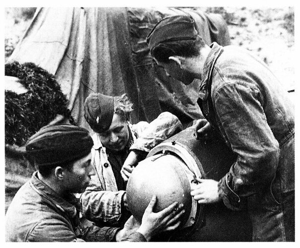
The following is a well recycled picture of a V-1 ground-crew man-handling a V-1 flying bomb on it's ground trolley. Unless my eyes deceive me the characteristic nose profile of the usual V-1 we're all used to seeing is distinctly lacking the normal ogival shape and instead, it looks for all the world like a bucket-shaped protective shield has been placed over the nose. ....or perhaps the factory made design changes to the previous nose-cap? Obviously, at this point in the pre-lauch procedures the Veeder-counter propeller has not been installed until just prior to locking the V1 to the launch ramp.
abschuss-ramp-v1_stellung_ligescourt.jpg
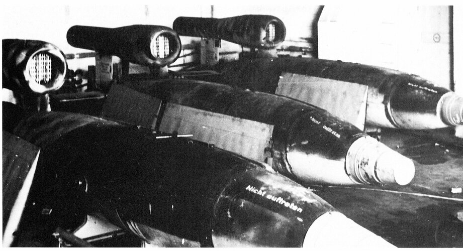
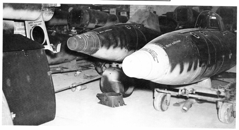
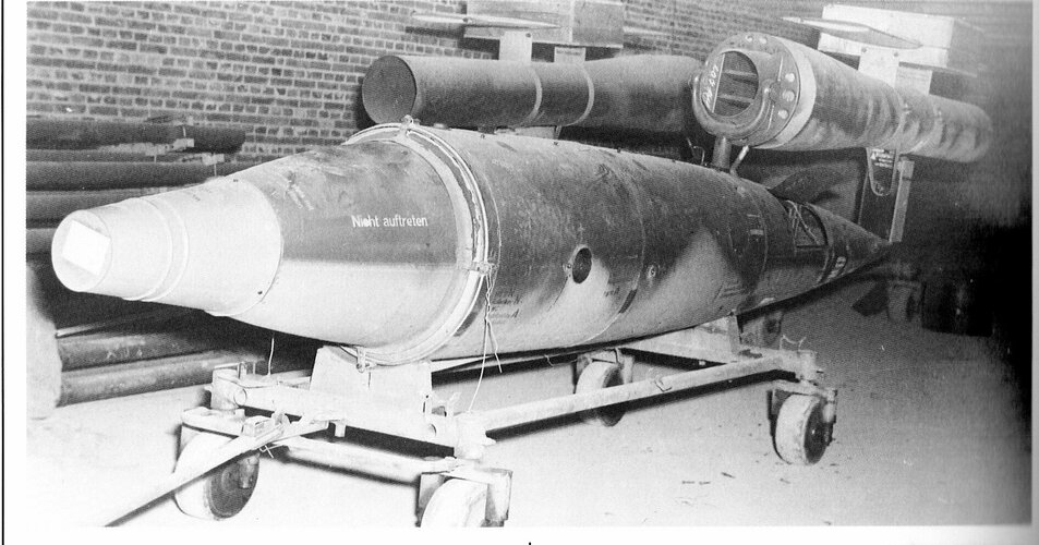
Compare this picture to the more common pictures one usually sees of similar pre-flight ground manoeuvres:
download (1).jpg
So, the first obvious question: protective nose-cap 'bucket', or not? ....followed by; if "Yes, it's a bucket!" then what was its purpose? Was it purely to prevent mechanical collision damage to the Veeder counter odometer/compass or could it be more subtle, like inhibiting inadvertent magnetisation from the impingement of stray magnetic fields thus preventing rogue deflection of the directional compass-disc achieved by constructing the bucket as a shield made out of Mu-metal? ...and, if this was the case, then when was this procedural change introduced since this is just about the only photo that shows this cover installed, every other picture of a V1 on the ground shows the nose uncovered: early handling procedure subsequently found to be of no merit, then quickly omitted or else found to be necessary and therefore instituted late in the V1 campaign? Anyone know??
As a brief diversion, that mention of de-magnetisation (above) prompts me to comment on the German practice for demagnetising the V1's steel fuselage. How many of you know what this 'process' entailed? Well, just prior to launch the missile was hauled into a wooden building containing no iron within its structure and the de-magnetisation team applied the super-sophisticated, high-tech process of frantically attacking the beast with wooden mallets! Seriously, that's how it was done which also neatly explains why you will see quite a number of pictures of V1's with numerous indentations which heretofore you may have just passed off as handling, transit damage. As but one example, there is a well-known picture of a V1 Having just left the end of the launch pad which displays what appears to be a large longitudinal cleft just behind the nose. The moral of the story: when press-ganging the locals into the de-magnetisation crew don't include the village black-smith!
gettyimages-566455763-612x612.jpg
 
The V-1 was shipped with a transport cone to protect the nose - it also contained the warhead fuzes that weren't attached until before launch.
 

Attachments

  • v1.png
    v1.png
    150.2 KB · Views: 36
Last edited:
The V-1 was shipped with a transport cone to protect the nose - it also contained the warhead fuzes that weren't attached until before launch.
No cigar I'm afraid! Things are never so simple. There was no impact fuse on the nose tip. The extremity of the nose was occupied by the airlog veeder counter assembly behind which sat the wooden compass sphere. Moreover, there wasn't 'a' fuse; there were (initially) two and later, a third mechanical 2-hour time delay fuse. One of the first two was a belly-impact fuse -and, by the way, probably more susceptible to handling damage than the other. The latter's location I haven't been able to precisely determine but by now I think that you're getting the gist that a mere, single 'bucket' isn't going to suffice nor provide a satisfactory explanation.
However, that is a brilliant photo and not one I've ever seen before. At least this positively confirms that it is no trick bad photography but a real piece of hardware.
 
I'm sorry if I was unclear - the fuses were only stored in the cone during transport.

The technical term is Bugspitzenschutzhaube but they were just buckets.
 
Last edited:
Heres an interesting couple of pics
Fi-103_Manned.jpg
4755a28c512a1c0c18563ca8f1ecb5d6.jpg

Looks like its a manned variant and it also has the protective nose cap.
Theres a very good post in a previous fi103/v1 thread here which has line drawings of the various warheads
 
"Bugspitzenschutzhaube" was really a good clue ! The complete, original manual is available via Wikipedia, as
I just found out !
The link for the first part is https://de.wikipedia.org/wiki/Datei:Fieseler_Fi-103_Ger%C3%A4tehandbuch_Teil_1.pdf#file,
for the others, just replace the number in "..._Teil_1" . Part 2 consists of two files.
It's correct, that there was no impact fuse directly in the nose, as can be seen in that drawing,
from the "FZG 76 Gerätehandbuch, Teil 4 Zünderanlage" (manual for the detonator installation),
part 4, page 12.
But there was an impact switch directly behind that small prop. If this had to be protected, or rather the prop or
whatelse, I don't know. The nose was made from aluminium, to prevent interference with the compass, part 1, page 6.
The "Bugspitzenschutzhaube" can be seen in part 1, page 1, and its fitting (3 bolts) is described on page 14.
 

Attachments

  • Fi-103_fuse.jpg
    Fi-103_fuse.jpg
    169.7 KB · Views: 25
I'm sorry if I was unclear - the fuses were only stored in the cone during transport.

The technical term is Bugspitzenschutzhaube but they were just buckets.
No, that can't be right. It would breach every military safety protocol in existence to ship fuses in proximity to an explosive warhead even if stored in the bucket. Fuses would normally be shipped separately from the weapon and only brought together at the pre-assembly staging area immediately prior to launch.
I think we also need to clarify the terminology so that we carefully discriminate between the functional components in the detonation train. The impact trigger switches are entirely different than the fuses they are intended to activate. The fuses themselves are installed in two vertical pockets atop the warhead. They would be connected by wiring to the impact switches.
 
Translation from the manual, part 4 (fuse installation, fitting of the fuse installation):
"a) The impact trigger switch: The protecting cover has to be removed from <Membrankopf> (part with the
membran) before installation (pic.5)

b) the <Gleitschalter) (slide switch ?), (pic.6): The electrical part of the fuse installation has to be installed
bipolar without ground connection.

After installation, the parts of the impact fuse has to be checked.

....

The fuses have to be installed in the <Einstellhaus> (building, where all adjustments are done) ... "

To me that means, the fuses FZG 76 was assembled, adjustments to course and fuse settings done, then
it was moved to the launch site, where the trigger switches were installed.
 

Attachments

  • pic-6.jpg
    pic-6.jpg
    152.7 KB · Views: 15
  • pic-5.jpg
    pic-5.jpg
    99.9 KB · Views: 11
Good information Jemiba. Procedurally safe as well. Obviously factory-sealed. Firing circuit must have been routed via contacts on the Veeder counter in the rear control/gyro compartment to obtain the necessary arming distance delay after launch.
 
The fuses were transported to the launch site in separate boxes (36 fuses per box), not in the "bucket" on each V1.

That would be too dangerous as xylstra already pointed out. Moreover there would not be enough room in the bucket for the nose cone with rotor, as well as all fuses.

Zaloga (in his books) seems to think they were, but I suspect that is the result of wrong interpretation of German texts. The bucket did not contain fuses but merely the impact switch (Aufschlagschalter) that was inside the nose cone, which was inside the bucket.

The V1 had three fuses:
- an electrical activated fuse at the front middle of the explosive charge (warhead)
- a mechanical impact fuse in a tube on top of the V1, inserted into the warhead
- a mechanical fuse with a time delay in a tube on top of the V1, inserted into the warhead

The electrical fuse was activated either by the impact switch in the nose (between rotor and compass) or by the glide switch at belly underside.
The impact switches were already installed in the factory. After testing the nose cone was removed and the nose covered with a rounded cap (blue arrow). The nose cone was put in the bucket (closed by a cover), which was then attached below the engine at the tail of the V1. The wings were placed on each side, thereby also protecting the bucket (red arrow):

V1 bucket and nose vover.jpg

That was the intend. There are however photos (like the one in Zaloga's book) on which the bucket is already on the nose cone while the warhead was not even inserted between fuel tank and nose cone. Apparently it was not always done as originally intended by the designers.

The two mechanical fuses each had a safety pin inside, with a ring on top. When the V1 was on the launching ramp a cable was connected to each ring. When launched the cable pulled out the safety pins.

The mechanical impact fuse was, several minutes after launch (after a certain safe distance), activated in flight by the counting device. I think also the electrical circuits with the nose and belly impact switches were then activated by the counting device.

The mechanical fuse with time delay was, before launch, set at the estimated flight time plus an extra margin.
 
Last edited:
Yes, looking through Göran Jansson's site and reading the manual made me suspect that Zaloga was wrong - maybe because the fuzes had their own protective caps?

Thank you for resolving the question using normal human communication skills.
 
The fuses came from a different factory than the factory that fabricated the V1. The same applies to the warhead.
On the photo that you posted you can see that there is a difference in diameter between the front part and the rest of the V1. At another site those two parts were disconnected and the warhead inserted. The warhead was somewhat conical with largest diameter at back.

The factory that fabricated the V1 installed the nose and belly switches and put the nose tip in the bucket. They did not install or include the fuses in any way.

The fuses were sent from their fabricator directly to the launching site in containers for 36 fuses each (12 packages of 3) for 12 V1's. The fuses were installed in the V1 in the Einstellhaus (later: Einstellzelt) shortly before the launch.
 
Noses & fuses
 

Attachments

  • 029.jpg
    029.jpg
    283.2 KB · Views: 18
  • 030.jpg
    030.jpg
    766.7 KB · Views: 19
  • 024.jpg
    024.jpg
    449.7 KB · Views: 20
  • 025.jpg
    025.jpg
    253.1 KB · Views: 15
  • 026.jpg
    026.jpg
    536.8 KB · Views: 20
  • 027.jpg
    027.jpg
    647.4 KB · Views: 18
  • 028.jpg
    028.jpg
    672.6 KB · Views: 21
The fuses were transported to the launch site in separate boxes (36 fuses per box), not in the "bucket" on each V1.

That would be too dangerous as xylstra already pointed out. Moreover there would not be enough room in the bucket for the nose cone with rotor, as well as all fuses.

Zaloga (in his books) seems to think they were, but I suspect that is the result of wrong interpretation of German texts. The bucket did not contain fuses but merely the impact switch (Aufschlagschalter) that was inside the nose cone, which was inside the bucket.

The V1 had three fuses:
- an electrical activated fuse at the front middle of the explosive charge (warhead)
- a mechanical impact fuse in a tube on top of the V1, inserted into the warhead
- a mechanical fuse with a time delay in a tube on top of the V1, inserted into the warhead

The electrical fuse was activated either by the impact switch in the nose (between rotor and compass) or by the glide switch at belly underside.
The impact switches were already installed in the factory. After testing the nose cone was removed and the nose covered with a rounded cap (blue arrow). The nose cone was put in the bucket (closed by a cover), which was then attached below the engine at the tail of the V1. The wings were placed on each side, thereby also protecting the bucket (red arrow):

View attachment 646304

That was the intend. There are however photos (like the one in Zaloga's book) on which the bucket is already on the nose cone while the warhead was not even inserted between fuel tank and nose cone. Apparently it was not always done as originally intended by the designers.

The two mechanical fuses each had a safety pin inside, with a ring on top. When the V1 was on the launching ramp a cable was connected to each ring. When launched the cable pulled out the safety pins.

The mechanical impact fuse was, several minutes after launch (after a certain safe distance), activated in flight by the counting device. I think also the electrical circuits with the nose and belly impact switches were then activated by the counting device.

The mechanical fuse with time delay was, before launch, set at the estimated flight time plus an extra margin.
Well done! A most thorough description. Cheers.
 
In the top left corner of Justo's photo number 027 one can clearly see the attachment under the engine exhaust with the circular hole intended for the bucket.

A photo showing V1's with the simple rounded cover on the nose:
Items on the foreground are engine intake nacelles.
 

Attachments

  • V1 with rounded nose cover.jpg
    V1 with rounded nose cover.jpg
    124.5 KB · Views: 23

Similar threads

Back
Top Bottom