
You are using an out of date browser. It may not display this or other websites correctly.
You should upgrade or use an alternative browser.
You should upgrade or use an alternative browser.
Westland Westminster
- Thread starter Barrington Bond
- Start date
hesham said:Hi,
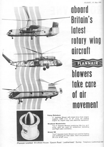
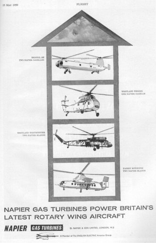
the Westland Westminster projects from Flightglobal;
http://www.flightglobal.com/pdfarchive/view/1959/1959%20-%202347.html
Hi,
Note the Wessex doing a loop the loop.
I saw the same in September 1960, first time I saw a heliocopter do that. Naval trials 8**?squadron
Barrington Bond said:From "The Fifteen Nations" No 11 September 1959.
Wouldn't having the power plant aft of the rotor cause trim problems? Also there are no obvious air intakes for the Turbines?
Rgds
Hi boys:
looking for another subject, I found that JPG of the wooden mock-up of an helicopter. I can remember only that was a postwar British design and that failed to reach the flyable hardware status.
Could someone of you help me about the type and the manufacturer?
Many thanks
Nico
Mod edit: image removed -better copy below
- Joined
- 6 November 2010
- Messages
- 4,221
- Reaction score
- 3,142
Westland Westminster. I found your picture on this site: http://members.multimania.co.uk/ctyoung57/Westminster/ww10.htm - but turn on your ad-blocker if you visit it.
- Joined
- 28 November 2006
- Messages
- 699
- Reaction score
- 637
Arjen said:but turn on your ad-blocker if you visit it.
I blocked pop-up windows (in my Firefox) but what still appears over there is really annoying, esp. the cockcrow!!!
Piotr
Matej
Multiuniversal creator
For a better access to the content of the web without very annoying advertisement:
Development
The early part of the 1950s saw Westland pursuing a design for a large heavy-lift helicopter for both civil and military applications. The new model was to be gas turbine powered. April 1951 saw the Yeovil firm responding to a British European Airways (BEA) requirement for a passenger helicopter. The Westland submission was for a 30-seat helicopter powered by a single Armstrong Siddeley Double Mamba engine. A year later saw a proposal for an even larger design, a fifty-seat machine with three Napier Eland gas turbines or four Rolls-Royce Dart engines. Projects in 1953 included a giant 400 seat Westland W.90 troop transport. None of these three transport helicopters were developed past the preliminary design phase.
In January 1954, Westland actively considered the licence production of the Sikorsky S-56, albeit with the original Pratt & Whitney radials replaced by Rolls Royce, Tyne or Mamba or even Napier Elands. The change-of engine would see the power plant side by side above the roof of the main cabin. The chairman of Westland's, Sir Eric Mensforth, later wrote to the Ministry of Supply (MoS) asking for funding for the S-56 development. July 1954 saw the company provide the MoS with a specific proposal that padded out their original submission. Further negotiations saw the company estimate that they could produce twelve S-56s by June 1958. Of the twelve quoted, five would have turboshaft engines. The lobbying by Westland carried little weight with the Government department and the project proposals failed to gain Governmental backing.
On 29th June 1955 negotiations were completed for Westland to extend their inter-company licensing agreement with Sikorsky to cover the S-56s main rotor, gearbox unit, tail rotor component as well as the transmission and control system. The rotor had five blades and featured a 72-foot diameter, the tail rotor was four bladed. Despite the loss of official backing, Westland took the decision to proceed with a private venture design for a heavy lift transport helicopter.
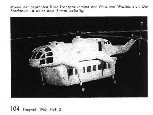
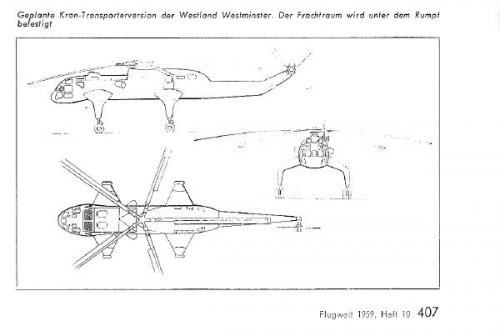
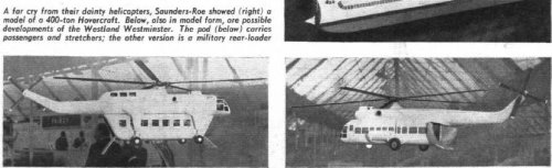
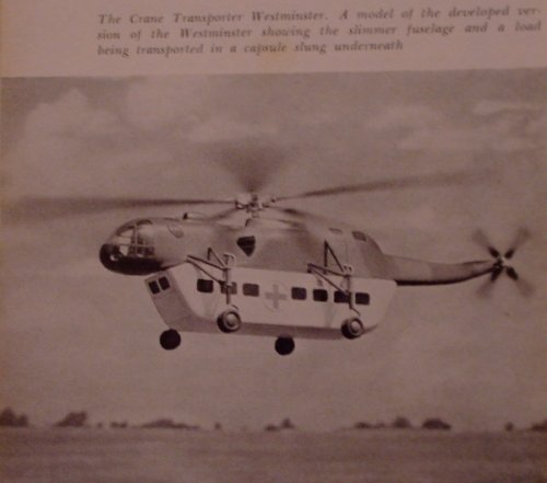
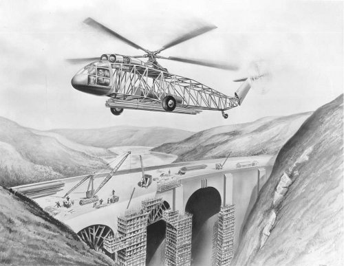
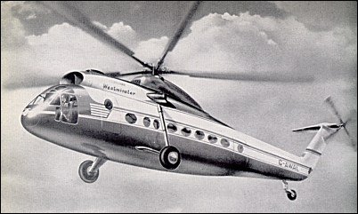
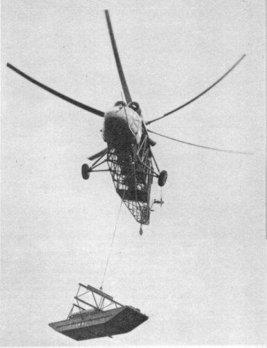
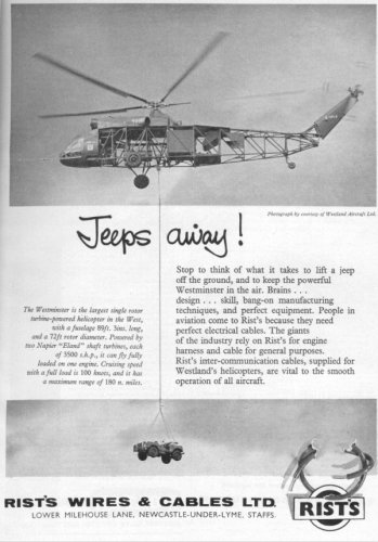
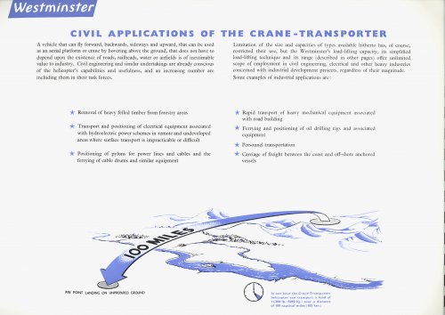
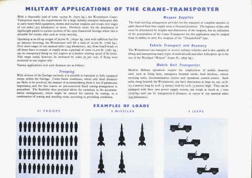
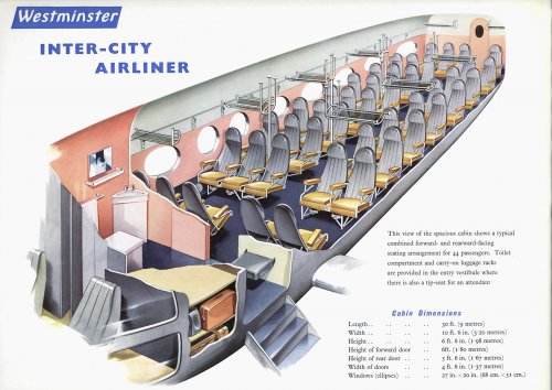
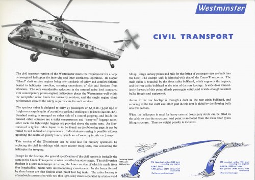
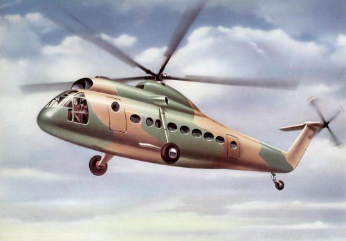
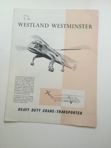
At the time, Westland had a prominent and heavy commitment to the Westland Wessex programme for the British military forces. This meant very few staff, engineering resources of financial allocations could be allocated to the new project. From the outset, two versions were identified; a short range civil transport and a flying crane. The civil transport would see the helicopter carrying around 40 passengers on trips of about 100 miles. The flying crane would be capable of carrying under-slung loads and outsize cargo. It would have the ability to lift a 15,000 lb load. It was designed to be able to carry up to fifty-one armed troops or four Jeeps.
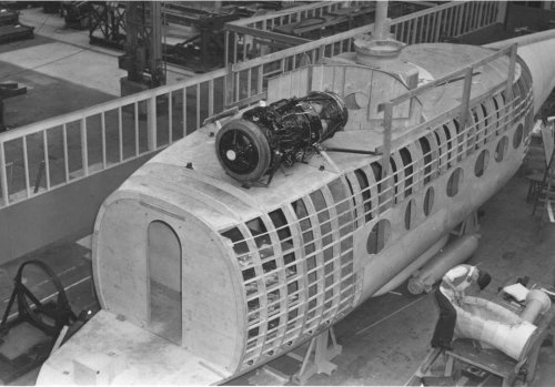
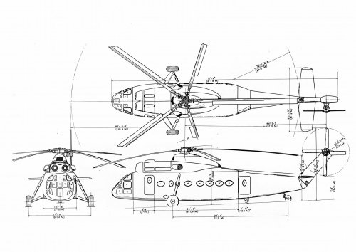
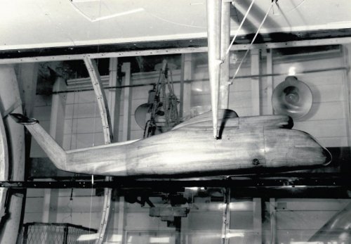
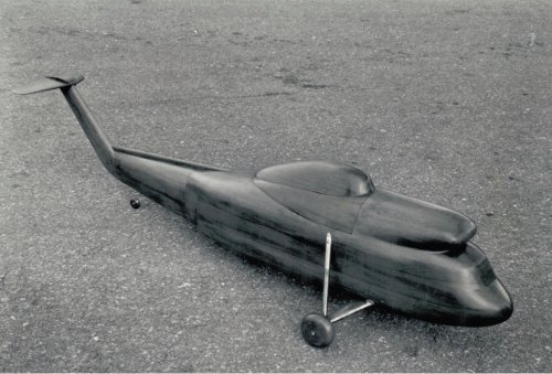
In Yeovil, a wooden mock-up of the civil versions cabin was manufactured. The layout saw eight rows of five seats abreast with luggage racks above the passenger's heads and doors located fore and aft of the cabin. 1955 saw the type named the Westminster.
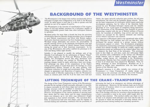
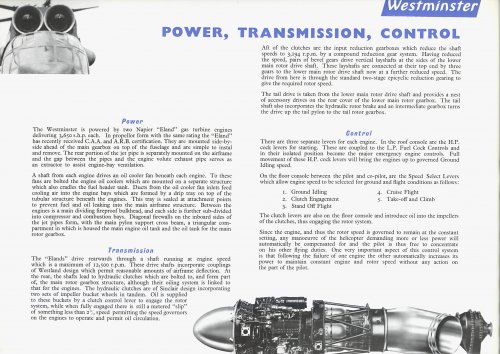
One of the features of the Westland development was the location of the engines on the cabin roof. This enabled the maximum exploitation of the internal volume, whether for cargo or passengers. The design also provided a new rotor drive system. The prototype was fitted with a pair of 2,920 shp Napier Eland E.229A turboshafts, which were a relatively light engine at 1,500 lb. This was the principal reason the cabin roof option could be exploited. The company became one of the pioneer manufacturers to take advantage of turboshaft engines good power to weight ratio in this way.
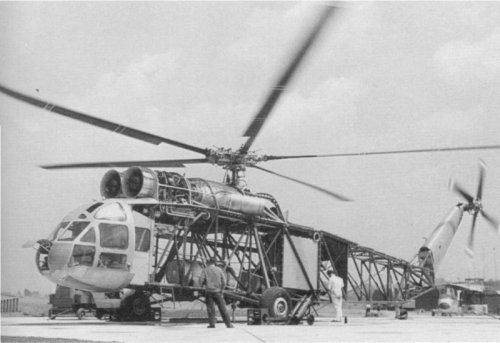
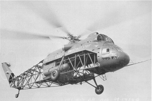
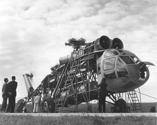
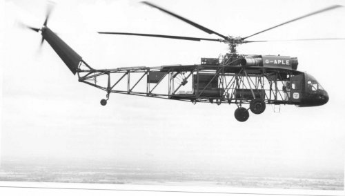
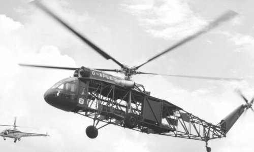
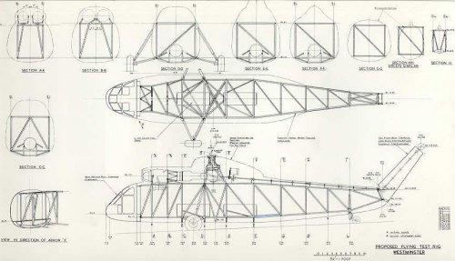
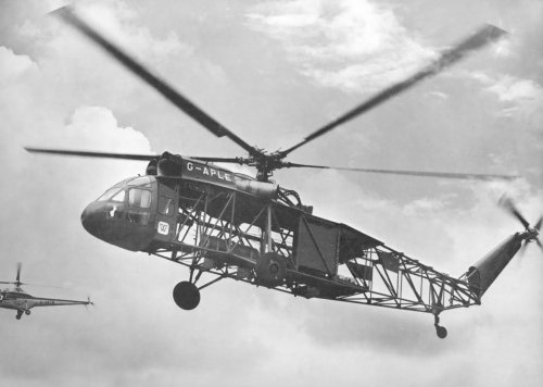
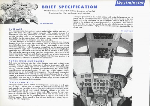
Westland's previous experience with the Whirlwind and Wessex models had shown the essential requirement for extensive testing for all of the dynamic components. In order to achieve this, a ground test rig was set up. March 1956 saw a flying test rig constructed to integrate the control and engine systems. The thinking behind the flying rig was to save time and money by developing areas such as the flight deck instruments and controls while evaluating the flying characteristics. The prototype, which carried the factory designation WG.6, was designed as the simplest welded steel tube space frame possible. It located the cockpit, engines, transmission, undercarriage and rotor systems in their correct positions for the civil passenger variant. Initially there was no specific fuselage layout.
The fuselage framework section tapered towards the rear and was basically a rectangular shape. The space frame was made up of steel tube modules that were jig-welded. These modules formed a two-part structure with four longerons and twelve rectangular frames. The frames had longitudinal and transverse diagonal compression struts. The forward section made up around 50% of the overall length and consisted of five bays of equal width and height. St the front of the tubular frame was the glazed fish head monocoque twin-seat cockpit area. The flight test observers station and instrumentation was located in a boxed off area behind the pilots.
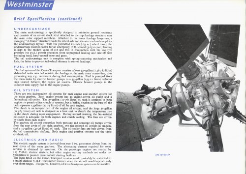
The aft part of the fuselage was made up of six bays of tapering rectangular section to which the tail rotor pylon was attached. Economy was one of the major factors in the design of the Westminster an existing Westland or Sikorsky components were utilised where possible. An example of this was the two 250 gallon fuel tanks, which were carried in the forward fuselage, were standard Westland Whirlwind overload units with an additional section incorporated. The undercarriage, attached to this part of the fuselage was originally intended to be the same as that fitted to the Wessex. However, design office calculations showed a risk of ground resonance and therefore a simpler design using one Dowty oleo-pneumatic shock absorber strut was used instead. The main wheels were from a Bristol B.170 Freighter cargo aircraft but with a reduced weight, achieved by removing 50% of the brakes. The Sikorsky S-56 provided the tail wheel unit.
The two engines were on loan from D Napier and Son. The main gearbox and rotor head together with the associated control equipment were carried on a platform attached to the top of the forward fuselage. Each of the engines was on trunnion mountings in its own isolated bay separated from the other by longitudinal and transverse fireproof bulkheads and entirely cowled. The tail rotor transmission ran in bearings mounted in transverse members on top of the rear fuselage, inside the rotor pylon, totally enclosed. The enclosed main gearbox turned the five all-metal bladed main rotor hub which had offset combined drag and flapping hinges to increase the centre of gravity envelope, and hydraulic drag dampers.
On the prototype the rotor system was five bladed main rotors and a four bladed anti-torque tail rotor. The main rotor had offset flapping hinges and hydraulically damped drag hinges. The Westminster was fitted with anti-coning and droop restrainers.
The landing gear was fixed with two wheels and a tailwheel. The helicopter was fitted with Dowty air and oil shock struts. The main wheels were manufactured by Dunlop, whereas the tailwheel was made by Goodyear.
The power plant installed in the Westminster was basically a constant-speed system in which variations in the load caused by pitch changes of the rotor provided a power demand ob the engines. Load changes caused a change in the revs per minute figures, which was picked up by the sensor in the governor on the engines, which subsequently adjusted the fuel input to maintain a constant speed.
Electric de-icing of both rotors was planned for production examples. The Westminster, in its cargo guise, was to have special freight loading doors and hoist facilities. An external slinging point was to be provided for those loads too bulky to be carried internally.
After the construction of the second example some development was put into proposals for a short-range version and a variant with detachable pods for carrying cargo or passengers.
Attachments
- Joined
- 6 November 2010
- Messages
- 4,221
- Reaction score
- 3,142
@ moderator:
I am aware this amounts to duplicating the source site; however considering all the extraneous elements there I thought I'd spare the SPF-visitors the visual overload on a site otherwise replete with interesting material. If you decide to remove these pictures - your call.
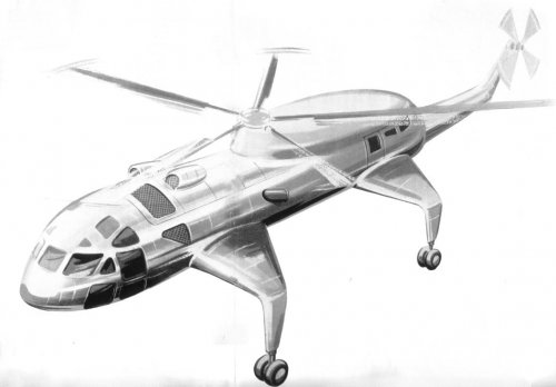
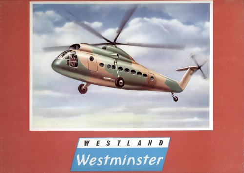
Artist's Impressions:
I am aware this amounts to duplicating the source site; however considering all the extraneous elements there I thought I'd spare the SPF-visitors the visual overload on a site otherwise replete with interesting material. If you decide to remove these pictures - your call.
Artist's Impressions:
Attachments

- Joined
- 6 November 2010
- Messages
- 4,221
- Reaction score
- 3,142
- Joined
- 6 November 2010
- Messages
- 4,221
- Reaction score
- 3,142
- Joined
- 6 November 2010
- Messages
- 4,221
- Reaction score
- 3,142

- Joined
- 6 November 2010
- Messages
- 4,221
- Reaction score
- 3,142
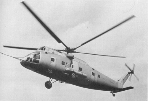
More information on the Westminster can be found in "Westland Aircraft since 1915" by Derek N James, Putnam, 1995. It relates why the Westminster was called "the flying cutaway drawing", how one was covered in plywood and Terylene® to make it appear more, well, 'finished' and what eventually led to its demise.
Specs from wikipedia (verifyably from the Putnam-Westland):
Specs from wikipedia (verifyably from the Putnam-Westland):
General characteristics
* Crew: 2 (+2 observers projected)
* Capacity: (projected) 40 passengers
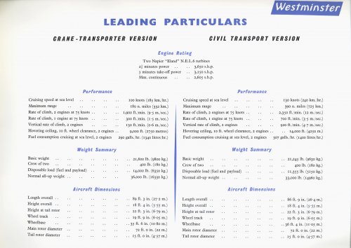
* Length: (including rotor) 89 ft 9 in (27.45 m)
* Fuselage length:[5] 71 ft 4 in (21.74 m)
* Rotor diameter: 72 ft 0 in (21.95 m)
* Height: 21 ft 1 in (6.43 m)
* Disc area: 4,069 ft² (378.2 m²)
* Empty weight: 21,245 lb (9,657 kg)
* Loaded weight: 33,000 lb (15,000 kg)
* Powerplant: 2× Napier Eland E220 turboshaft, 2,920 hp (2,178 kW) each
Performance
* Maximum speed: 155 mph (135 knots, 250 km/h)
* Cruise speed: 115 mph (100 knots, 185 km/h)
* Range: 120 mi (104 nmi, 193 km) estimated for production model
- Joined
- 6 November 2010
- Messages
- 4,221
- Reaction score
- 3,142
In an era when simulations were rare and very simple, this was a way of testing the components before having finished the entire design. Other examples of unfinished looking vehicles:
- Rolls-Royce Flying Bedstead http://en.wikipedia.org/wiki/Rolls-Royce_Thrust_Measuring_Rig
- SNECMA Atar Volant http://en.wikipedia.org/wiki/SNECMA_Atar_Volant
- Bell Aerosystems LLRV http://en.wikipedia.org/wiki/LLRV
- Rolls-Royce Flying Bedstead http://en.wikipedia.org/wiki/Rolls-Royce_Thrust_Measuring_Rig
- SNECMA Atar Volant http://en.wikipedia.org/wiki/SNECMA_Atar_Volant
- Bell Aerosystems LLRV http://en.wikipedia.org/wiki/LLRV
- Joined
- 20 January 2007
- Messages
- 892
- Reaction score
- 910
In the absence of a customer, Westland's 29/6/55 licence for S.56 was speculative, so sparsely, privately funded as a 3D brochure. Heavy rotors then funded by UK were Fairey Rotodyne and Bristol (to be) Belvedere. When those firms were folded into Westland, all lapsed against their 1959 licence for S.61, to be supreme Sea King.
- Joined
- 30 November 2007
- Messages
- 1,089
- Reaction score
- 429
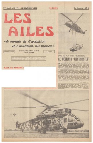
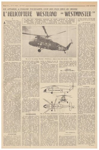
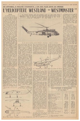
Dear Boys and Girls, here is an extensive 2 part article in French about the Westland Westminster helicopter prototype……
The articles come from the 14th & 21st November 1959 issues of Les Ailes......
Moderators:-
1. Shouldn't this topic be renamed Westland Westminster rather than Westminister (which is the incorrect spelling of the name)?
2. Shouldn't this topic be moved to Aerospace as it isn't a "project"; 2 prototypes were built and flown before cancellation?
Terry (Caravellarella)
The articles come from the 14th & 21st November 1959 issues of Les Ailes......
Moderators:-
2. Shouldn't this topic be moved to Aerospace as it isn't a "project"; 2 prototypes were built and flown before cancellation?
Terry (Caravellarella)
Attachments
-
 Westland Westminster helicopter prototype - Les Ailes - No. 1,751 - 14 Novembre 1959 1.......jpg103.7 KB · Views: 507
 -
 Westland Westminster helicopter prototype - Les Ailes - No. 1,751 - 14 Novembre 1959 2.......jpg172.1 KB · Views: 513
 -
 Westland Westminster helicopter prototype - Les Ailes - No. 1,752 - 21 Novembre 1959.......jpg145.4 KB · Views: 518
- Joined
- 27 December 2005
- Messages
- 16,415
- Reaction score
- 18,961
Forum rules:
The primary purpose of the "Secret Projects" sections of this forum is to document real, but unbuilt, projects. Prototypes that didn't enter series production may also be appropriate at the descretion of the moderators
The primary purpose of the "Secret Projects" sections of this forum is to document real, but unbuilt, projects. Prototypes that didn't enter series production may also be appropriate at the descretion of the moderators
- Joined
- 27 December 2005
- Messages
- 16,415
- Reaction score
- 18,961
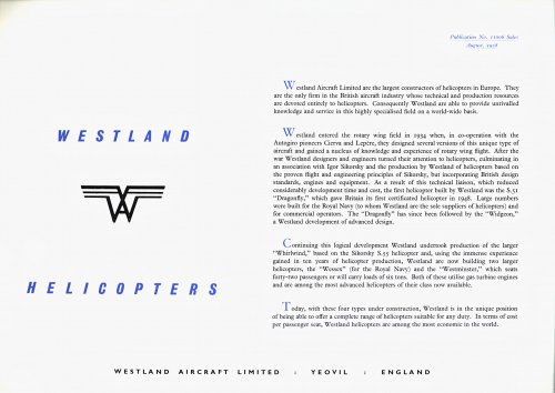
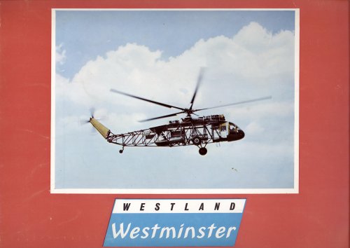
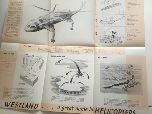
Although a prototype was flown, this design never entered series production. This sales brochure shows the unbuilt production versions.
(to be continued...)
(to be continued...)
Attachments
- Joined
- 27 December 2005
- Messages
- 16,415
- Reaction score
- 18,961
The rest. Note the inside back cover was white lines on dark blue which scanned very poorly, I have therefore edited it in GIMP to black and white.
Attachments
- Joined
- 25 June 2009
- Messages
- 13,745
- Reaction score
- 2,928
- Joined
- 27 December 2005
- Messages
- 16,415
- Reaction score
- 18,961
Not bad condition for 54 years old, that brochure ")
Found it here in New Zealand of all places.
Found it here in New Zealand of all places.
- Joined
- 25 June 2009
- Messages
- 13,745
- Reaction score
- 2,928
overscan said:Not bad condition for 54 years old, that brochure
Found it here in New Zealand of all places.
Wow. And probably for much cheaper than you would have paid for it in Britain, too...
- Joined
- 27 December 2005
- Messages
- 16,415
- Reaction score
- 18,961
It wasn't that cheap ($29USD) but postage was cheap and quick compared to normal
- Joined
- 27 September 2006
- Messages
- 5,744
- Reaction score
- 5,615
I am not sure whether it has been posted elsewhere but there is an excellent thread on Shipbucket about Project Cancelled aircraft which has some wonderful side views of the Westminster in RAF and BEA livery.
http://www.shipbucket.com/forums/viewtopic.php?f=20&t=1510&start=120
I think the author of the thread is a notable member of this site. The side views of the Westminster and other aircraft are really useful and a great resource
http://www.shipbucket.com/forums/viewtopic.php?f=20&t=1510&start=120
I think the author of the thread is a notable member of this site. The side views of the Westminster and other aircraft are really useful and a great resource
- Joined
- 11 March 2006
- Messages
- 8,606
- Reaction score
- 3,046
Thank you for pointing me to that site ! Was on shipbucket.com many times, but never noticed that section.
Just a question: Is there a source for the Westminster with nose wheel gear ?
Just a question: Is there a source for the Westminster with nose wheel gear ?
- Joined
- 6 September 2006
- Messages
- 4,308
- Reaction score
- 7,444
Thanks for posting that link UK75.
The nose-wheel military version of the Westland is taken from the drawing reproduced in Derek Wood's 'Project Cancelled' (2nd ed. 1986) on p.111. With clamshell rear doors and a revised tail boom and the detail changes from the basic twin-Eland civil version it would seem to be almost a fresh design using a standard Westminster engine and transmission unit and cockpit with an all-new fuselage and boom. You get the feeling had Rotodyne not been pursued the Westminster might have proven more suitable and the military version would have pre-dated the Puma but offered the kind of roll on-roll-off capability of the Mi-8.
The nose-wheel military version of the Westland is taken from the drawing reproduced in Derek Wood's 'Project Cancelled' (2nd ed. 1986) on p.111. With clamshell rear doors and a revised tail boom and the detail changes from the basic twin-Eland civil version it would seem to be almost a fresh design using a standard Westminster engine and transmission unit and cockpit with an all-new fuselage and boom. You get the feeling had Rotodyne not been pursued the Westminster might have proven more suitable and the military version would have pre-dated the Puma but offered the kind of roll on-roll-off capability of the Mi-8.
- Joined
- 28 January 2008
- Messages
- 628
- Reaction score
- 446
- Joined
- 1 May 2007
- Messages
- 2,458
- Reaction score
- 1,450
Although a prototype was flown, this design never entered series production. This sales brochure shows the unbuilt production versions.
Did this a while ago, but never got round to posting it... :-[
I made the brochure images into a PDF. It's available from here :-
http://sdrv.ms/15Y8kkZ
cheers,
Robin.
- Joined
- 29 January 2008
- Messages
- 834
- Reaction score
- 1,328
Similar threads
-
 Westland Wessex replacement before Puma (WG.4/WG.7/WG.8?)
- Started by uk 75
- Replies: 18
-
-

-
-