
- Joined
- 11 February 2010
- Messages
- 1,451
- Reaction score
- 1,954
Greetings all.
Well as the title said, about "wing loading" As far as i read.. that quantity along with T/W ratio are the "Layman's gate" to understand fighter aircraft agility and performance. Further reading at the L Shaw's Fighter Combat :Tactics and Maneuvering indicated that those two quantities allow four tactical "qualities" for fighter namely superiority in climb and dive (Energy) Superiority in horizontal maneuver (Angle fighter) Superiority in both and inferior in both Energy and maneuvering.
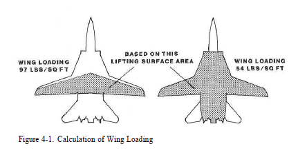
There's however one confusing thing for me, how should one calculate wing loading ? Should it be calculated based on "Wing reference area" OR "total lifting area" Which include some lifting portion of the fuselage (Say LERXes like Su-27) Usual data i saw however typically use wing reference area.
The Shaw's book however showed both approach here :

Which one that could give "closer to reality" value ? The one using reference wing area or the one using "total area that help wing to generate lift such as LERXes or that F-14's "tunnel" between engines" ?
Another thing is the engine thrust to weight ratio. The thing i noticed is that literature give data on the Static Uninstalled SLS thrust, meaning that the thrust value is measured when the engine is at testbench and at sea level altitude. Thus calculated T/W ratio might not be correct. One solution i found was to multiply that SLS thrust with 0.78 to account lossess caused by the inlet system. The source of that 0.78 value was Yefim Gordon's Famous Russian Aircraft book.
Furthermore i expanded it by literature (Raymer) To allow prediction of thrust value at various altitude and speed.
Nonetheless i wonder if my approach is acceptable ?
Hmm that is all of my questions. Thank you very much for any response from the community.
Well as the title said, about "wing loading" As far as i read.. that quantity along with T/W ratio are the "Layman's gate" to understand fighter aircraft agility and performance. Further reading at the L Shaw's Fighter Combat :Tactics and Maneuvering indicated that those two quantities allow four tactical "qualities" for fighter namely superiority in climb and dive (Energy) Superiority in horizontal maneuver (Angle fighter) Superiority in both and inferior in both Energy and maneuvering.
There's however one confusing thing for me, how should one calculate wing loading ? Should it be calculated based on "Wing reference area" OR "total lifting area" Which include some lifting portion of the fuselage (Say LERXes like Su-27) Usual data i saw however typically use wing reference area.
The Shaw's book however showed both approach here :
Which one that could give "closer to reality" value ? The one using reference wing area or the one using "total area that help wing to generate lift such as LERXes or that F-14's "tunnel" between engines" ?
Another thing is the engine thrust to weight ratio. The thing i noticed is that literature give data on the Static Uninstalled SLS thrust, meaning that the thrust value is measured when the engine is at testbench and at sea level altitude. Thus calculated T/W ratio might not be correct. One solution i found was to multiply that SLS thrust with 0.78 to account lossess caused by the inlet system. The source of that 0.78 value was Yefim Gordon's Famous Russian Aircraft book.
Furthermore i expanded it by literature (Raymer) To allow prediction of thrust value at various altitude and speed.
Nonetheless i wonder if my approach is acceptable ?
Hmm that is all of my questions. Thank you very much for any response from the community.