- Joined
- 1 May 2007
- Messages
- 2,459
- Reaction score
- 1,453
As a result of a question posted here :-
http://www.secretprojects.co.uk/forum/index.php/topic,2049.msg102240.html#msg102240
I've decided to start a new topic on the subject here, rather than clutter up the other topic with OT stuff...
'The HZ-Anlage system.
Developed as a means of retaining,or increasing, the power of a piston aero-engine at altitude, the HZ (hohenladerzentralle)-Anlage,
and it's counterparts, used the principle of 'two engines for the price of three', or four engines for the price of five', to use the
Gunstonian phrase.
The basic idea, was to use an extra engine, separate from those used for propulsion, to drive a large blower, the air from this, being
piped into the propulsion engines' own supercharger inlets. See Fig. 1.
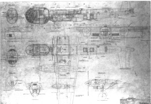
It was first used in 1916, during the Great War. The German Staaken R.VI, serial number.R.30/16, and powered by four 260hp
Mercedes D.IVa engines, was fitted with a large centrifugal supercharger in the fuselage, and driven by a Mercedes D.II engine of
120hp. The air was ducted to the engines via pipes running through the wing and into the engine nacelles. Fig. 2.
First flying in modified form on 23rd March 1918, on 24th April an altitude of 19,357ft was achieved, some 3,000ft in excess of the
aircraft's normal ceiling. Speed was also increased by some 30km/h, to 160km/h.
In WWII the concept re-surfaced as the HZ-Anlage. Fitted to the Dornier Do 217P and Henschel Hs 130E high-altitude
reconnaissance/bomber aircraft, It consisted of two wing-mounted Daimler-Benz DB603S propulsion engines, driving broad-chord
propellers, and a single fuselage-mounted DB605T. This drove a large blower (Gunston says a Roots-type, but Griehl says, and the
images appear to show, a centrifugal type). Fig. 3,4.
The air from this was delivered to the engines via underwing mounted intercoolers, and piped into the DB303's supercharger inlets,
Fig. 5,6,7,8.
The air intakes for the blower, and it's driving engine were fitted under the fuselage, along with the blower engine's radiator. Both
aircraft types were equipped with a pressure cabin, and during flight testing, both types reached altitudes of the order of 49,000ft
(15,000m).
In the Soviet Union, a similar installation was designed for the ANT-42 (TB-7, Pe-8) heavy bomber.
Known as the ATsN, Agregat Tsentralnovo Nadduva, in the ANT-42 prototype this comprised an M-100 engine of 750hp, mounted in
the upper fuselage, driving a centrifugal blower via step-up gearing, at 25,000rpm, the air being fed to the 950hp M-34FRN propulsion
engines through pipes routed along the rear spar. The M-100 was housed in a fireproof box, with the exhaust pipe running along the
fuselage right side. Fig. 9.
The second prototype, the ANT-42 dubler, was fitted with the ATsN-2, utilising an M-100A blower engine of 850hp, and improved AM-
34FRNB propulsion engines, rated at 1,200hp. Production aircraft were to have had the further improved M-103 blower engine.
THe ANT-42 was accepted for service as the TB-7, however continuing development problems, and engine shortages, caused the
abandonment of the ATsN system, the TB-7 being re-engined with 1,200hp AM-35s.
Russian speakers may wish to visit
http://www.airwar.ru/enc/bww2/ant42.html
(I'm not sure if there is more information there, as I can't read a word of it.)
Finally, Avro proposed the Type 684 Statospheric Bomber.
For more information, see here :-
http://www.secretprojects.co.uk/forum/index.php/topic,642.msg4993.html#msg4993
Sources :- Putnam's 'The German Giants', 'Piston Aero Engines' (Gunston), 'Do 217-317-417' (Griehl), Putnam's 'Tupolev',
http://www.airwar.ru/enc/bww2/ant42.html
cheers,
Robin.
http://www.secretprojects.co.uk/forum/index.php/topic,2049.msg102240.html#msg102240
I've decided to start a new topic on the subject here, rather than clutter up the other topic with OT stuff...
'The HZ-Anlage system.
Developed as a means of retaining,or increasing, the power of a piston aero-engine at altitude, the HZ (hohenladerzentralle)-Anlage,
and it's counterparts, used the principle of 'two engines for the price of three', or four engines for the price of five', to use the
Gunstonian phrase.
The basic idea, was to use an extra engine, separate from those used for propulsion, to drive a large blower, the air from this, being
piped into the propulsion engines' own supercharger inlets. See Fig. 1.
It was first used in 1916, during the Great War. The German Staaken R.VI, serial number.R.30/16, and powered by four 260hp
Mercedes D.IVa engines, was fitted with a large centrifugal supercharger in the fuselage, and driven by a Mercedes D.II engine of
120hp. The air was ducted to the engines via pipes running through the wing and into the engine nacelles. Fig. 2.
First flying in modified form on 23rd March 1918, on 24th April an altitude of 19,357ft was achieved, some 3,000ft in excess of the
aircraft's normal ceiling. Speed was also increased by some 30km/h, to 160km/h.
In WWII the concept re-surfaced as the HZ-Anlage. Fitted to the Dornier Do 217P and Henschel Hs 130E high-altitude
reconnaissance/bomber aircraft, It consisted of two wing-mounted Daimler-Benz DB603S propulsion engines, driving broad-chord
propellers, and a single fuselage-mounted DB605T. This drove a large blower (Gunston says a Roots-type, but Griehl says, and the
images appear to show, a centrifugal type). Fig. 3,4.
The air from this was delivered to the engines via underwing mounted intercoolers, and piped into the DB303's supercharger inlets,
Fig. 5,6,7,8.
The air intakes for the blower, and it's driving engine were fitted under the fuselage, along with the blower engine's radiator. Both
aircraft types were equipped with a pressure cabin, and during flight testing, both types reached altitudes of the order of 49,000ft
(15,000m).
In the Soviet Union, a similar installation was designed for the ANT-42 (TB-7, Pe-8) heavy bomber.
Known as the ATsN, Agregat Tsentralnovo Nadduva, in the ANT-42 prototype this comprised an M-100 engine of 750hp, mounted in
the upper fuselage, driving a centrifugal blower via step-up gearing, at 25,000rpm, the air being fed to the 950hp M-34FRN propulsion
engines through pipes routed along the rear spar. The M-100 was housed in a fireproof box, with the exhaust pipe running along the
fuselage right side. Fig. 9.
The second prototype, the ANT-42 dubler, was fitted with the ATsN-2, utilising an M-100A blower engine of 850hp, and improved AM-
34FRNB propulsion engines, rated at 1,200hp. Production aircraft were to have had the further improved M-103 blower engine.
THe ANT-42 was accepted for service as the TB-7, however continuing development problems, and engine shortages, caused the
abandonment of the ATsN system, the TB-7 being re-engined with 1,200hp AM-35s.
Russian speakers may wish to visit
http://www.airwar.ru/enc/bww2/ant42.html
(I'm not sure if there is more information there, as I can't read a word of it.)
Finally, Avro proposed the Type 684 Statospheric Bomber.
For more information, see here :-
http://www.secretprojects.co.uk/forum/index.php/topic,642.msg4993.html#msg4993
Sources :- Putnam's 'The German Giants', 'Piston Aero Engines' (Gunston), 'Do 217-317-417' (Griehl), Putnam's 'Tupolev',
http://www.airwar.ru/enc/bww2/ant42.html
cheers,
Robin.
Attachments
-
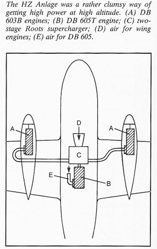 Fig 1 - HZ-Anlage schematic.png118.9 KB · Views: 178
 -
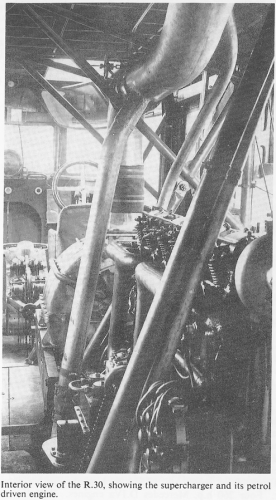 Fig. 2 - scan0008.png377.8 KB · Views: 166
 -
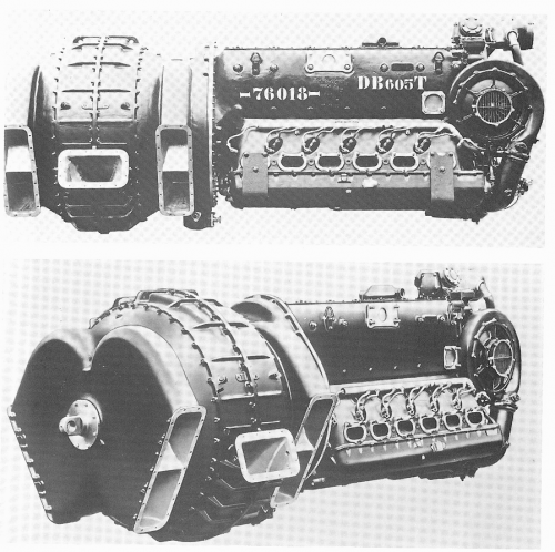 Fig. 3 - DB 605T - HZ-Anlage blower.png608.3 KB · Views: 154
 -
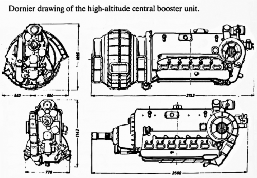 Fig. 4 - HZ-Anlage blower drawing.png207.7 KB · Views: 131
 -
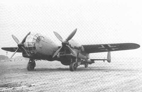 Fig. 5 - Do217P.png343.7 KB · Views: 125
 -
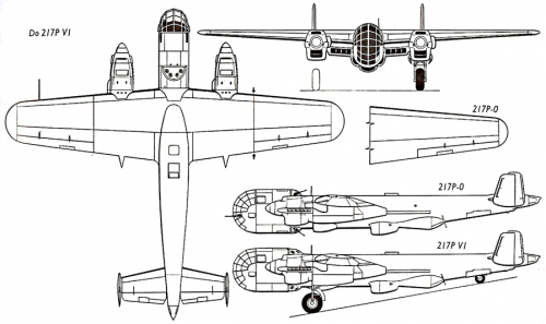 Fig. 6 - Do217P 3-view.png69.6 KB · Views: 51
 -
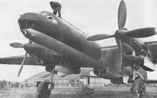 Fig. 7 - Hs130E.png433.2 KB · Views: 44
 -
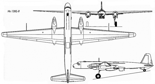 Fig. 8 - Hs130E 3-view.png68.4 KB · Views: 54