Taiwan Naval Projects

Ingraman

I really should change my personal text
Joined
24 September 2013
Messages
52
Reaction score
116
A couple of images I found in old H.D. for a second batch of Kwang Hua I program.
Original K.H. I Flight 1 PFG-2 was the FFG7 Perry, with minimal modifications.
Flight 2 was intended as AAW ship, with the ADAR-2N phaesd array radar.
32 or 48 VLS proposed, 4500 ton.
ADAR-1 was a land based radar connected with the Tien Kung 1 (or Tien Kung I) SARH missile.
 

Attachments

  • TAIWAN pfg-2 cmar1 adar-2n radar 01.jpg
    TAIWAN pfg-2 cmar1 adar-2n radar 01.jpg
    24.7 KB · Views: 349
  • taiwan navy acs0001_8839.jpg
    taiwan navy acs0001_8839.jpg
    31.7 KB · Views: 299
  • RADARv002.jpg
    RADARv002.jpg
    298.2 KB · Views: 331
This link, in Chinese, has a detailed description of the Flight II ADAR-2N equipped frigate referenced by Ingraman above and dating to 1994. It's fascinating to see how much Gibbs and Cox could squeeze into the basic FFG-7 class hull and single shaft propulsion configuration; 48 Mk-41 VLS, a 5" gun, 2 Phalanx, 8 AShMs and what was essentially SPY-1F.

From an alternative history perspective, given the 1994 date, a variation of this design could have been a candidate to replace the USN's Knox class frigates had the Cold War not ended. 48 VLS cells being sufficient for a reasonable number of AAW missiles in addition to VL-ASROC or Sea Lance.
 

Attachments

  • Taiwan_ACS_Frigate_IV.png
    Taiwan_ACS_Frigate_IV.png
    405.2 KB · Views: 278
  • Taiwan_ACS_Frigate_I.jpeg
    Taiwan_ACS_Frigate_I.jpeg
    12.7 KB · Views: 274
  • Taiwan_ACS_Frigate_II.jpg
    Taiwan_ACS_Frigate_II.jpg
    67.8 KB · Views: 257
  • Taiwan_ACS_Frigate_III.jpg
    Taiwan_ACS_Frigate_III.jpg
    11.4 KB · Views: 337
Last edited:
I have a Navy briefing from a Frigate market survey, undated but probably done around the mid-1990s. Can't post the full slide but a couple of interesitng items pop out.

1) This design required a 45' stretch compared to the last FFG-7 (FFG-61 USS Ingraham). Full load displacement rose to more than 5000 tons, versus just over 4000 for FFG-61. (JFC Fuller's link shows this grew even further, to nearly 6000 tons)

2) The US Navy assessors had some concern about the stability solution chosen -- high freeboard and low metacentric height. In other words, this ship would roll, a lot, and rely on not quite burying the rail for recovery. This sounds like a recipe for inadequate damaged stability to me.
 
Did it retain the single screw and powerplant of the OHP's, or was it changed to a twin screw arrangement and revised power plant?
 
Impressive but as TomS says, probably impractical due the constraints inherent with stretching a ship too far.
It looks like a complete redesign topside and the stretch must have altered the hullform somewhat. Wouldn't it have been easier to just start again from scratch to design a proper export frigate?
 
Putting the text into google translate here are the actual data (not 5" gun but 3" )
There seems to be two designs, the first was a modification of the Cheung Kung as it uses the same hull, the other later version was a much larger ship.

Dimensions:
138,1 x 14,3 meters
151 x 15 (minimum) meters (late design)
Displacement: 6.000tons (full load, late design)
Engines: Not clear on the shp but 1 shafts General Electric LM2500 not sure if one gas turbine or two, shp stated at 41.000 so probably two turbines on the single shaft
Armaments:
First Design:
2x4 Hsiung Feng II AshM,
1x1 76mm/62 Mark 75 (OTO-Malera Compact?)
4x8 RIM-66 Standard MR SAM (Mk-41 VLS for SM-2MR)
1-2x21 RIM-116 RAM CIWS/SAM or Barak-1 SAM
2x1 40mm/70 Bofors probably Breda Type 564 CIWS
1-2x6 20mm/76 Phalanx Mark 72 CIWS
2x3 324mm Torpedo Tubes
2x S-70 Seahawk Helicopter

Late Design:
2x4 RGM-84 Harpoon AshM,
1x1 76mm/62 Mark 75 (OTO-Malera Compact?)
6x8 RIM-66 Standard MR SAM (Mk-41 VLS for SM-2MR and VL-ASROCK)
1-2x21 RIM-116 RAM CIWS/SAM or Barak-1 SAM
2x6 20mm/76 Phalanx Mark 72 CIWS
2x3 324mm Torpedo Tubes
1x S-70 Seahawk Helicopter
 
A couple of images I found in old H.D. for a second batch of Kwang Hua I program.
Original K.H. I Flight 1 PFG-2 was the FFG7 Perry, with minimal modifications.
Flight 2 was intended as AAW ship, with the ADAR-2N phaesd array radar.
32 or 48 VLS proposed, 4500 ton.
ADAR-1 was a land based radar connected with the Tien Kung 1 (or Tien Kung I) SARH missile.

Thanks for that. I've read a lot about the PFG Flight 2, but have never seen an image before....

Regards,
 
Just found in my paper files 
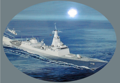
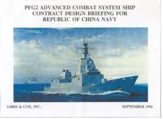
a 1995 ASNE Symposium briefing on this ship (link is just to a library reference, sorry), which the authors describe simply as an Advanced Frigate.

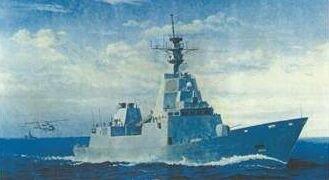
It's quite close to the late model design above. At this stage, length overall was 498 feet (151.8 m), with a design full load of 5000 tons and a limiting displacement of 5308 tons. The hull had minimal mods around the bow, stern, shaft lines and flight deck geometry but was stretched midships by 45 feet in length and 5.6 feet in beam (only 2.5 feet at the waterline; the hull flares out noticeably above that).

Machinery is basically unchanged from the FFG-7, meaning two LM2500 and four ship service diesel generators. The main difference is a new chilled water system, which the new radar would need.

Steel structure up to the 01 deck and high strength steel on the upper strength deck (the FFGs used mild steel, which is a lot cheaper) then aluminum for the two deckhouses above that. Protection of some sort (some steel, some kevlar, some just spaced) for key spaces (basically the VLS, the gun magazine, CIC, the electronics spaces, the PAR waveguide, the torpedo launcher room, and the engineering central control room).

Armament includes a 5-inch gun in a shaped housing, not a 3-inch, and two RAM as well as two Phalanx (no Barak -- this version looks like it might have been intended for the US Navy?)

Interestingly, the drawing has 2 RAST tracks and dual hangars with the helo control station cab between them, not a single hangar. Looks a lot like a baby Flight IIA Burke.

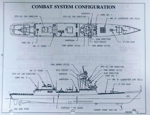
There is a fair bit about the combat system, but nothing terribly new to folks familiar with how AEGIS works. Some surprisingly detailed range and coverage charts, but I suspect they are notional, not real.

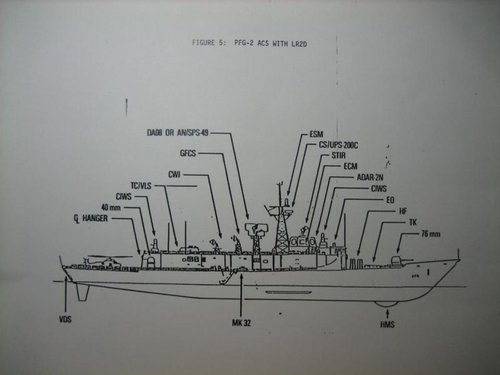
Edit: Added a scan of the general combat system arrangements.
 

Attachments

  • Advanced Frigate Combat System Configuration.jpg
    Advanced Frigate Combat System Configuration.jpg
    700.8 KB · Views: 377
Last edited:
Impressive but as TomS says, probably impractical due the constraints inherent with stretching a ship too far.
It looks like a complete redesign topside and the stretch must have altered the hullform somewhat. Wouldn't it have been easier to just start again from scratch to design a proper export frigate?

Looking at it, I think there was a lot of influence from this design into the G&C International Frigate concept. Similar topsides arrangement in many ways, though the later design has separated machinery spaces and a second stack, so very different internally.
 

Similar threads

Back
Top Bottom