Just so that I can avoid taking the other thread off topic, for all this argument of a massive difference in capture area, based on properly scaled front views of the Su-57 and the F-22 from official sources (Sukhoi's patent and Lockheed Martin), I'm getting a difference on the order of 5%. Mind you, in propulsion terms, 5% is not insignificant, but the actual flow field the inlets see will be different from a head on view, and given the functions that the inlet flow serves in addition to propulsion, frankly this difference is not worth noting.
I will review my measurements, it was a long time ago when I did them. But I was careful and I was surprised with the results, I was expecting them to have quite similar capture areas
I will review my measurements, it was a long time ago when I did them. But I was careful and I was surprised with the results, I was expecting them to have quite similar capture areas
I've edited my attachment to highlight the capture areas with a red perimeter, for clarity. Again, inlet design consist of tradeoffs, and a larger area does not necessarily indicate superior supercruise performance for reasons of ram compression and spillage.
For general media, here is some VR footage of the Su-57 in flight.
See the image I used for my original intake capture area calculation. Su-57 is +23% compared to Flanker, +31% compared to F-22. If the drawings are not correct, then the values are also not correct, but at that time I took these for valid sources (are they from you paralay?). The ones you based your measurement on are, for the Su-57, quite low detail and I am not fully convinced. I guess the trick to get a more definitive value is to find and use proper blueprints.
For the record, I still consider it not reasonable to deny that bigger intakes are motivated by a bigger mass flow consumption demand and don't see what those alleged very different design points between fighters with the same roles would be.
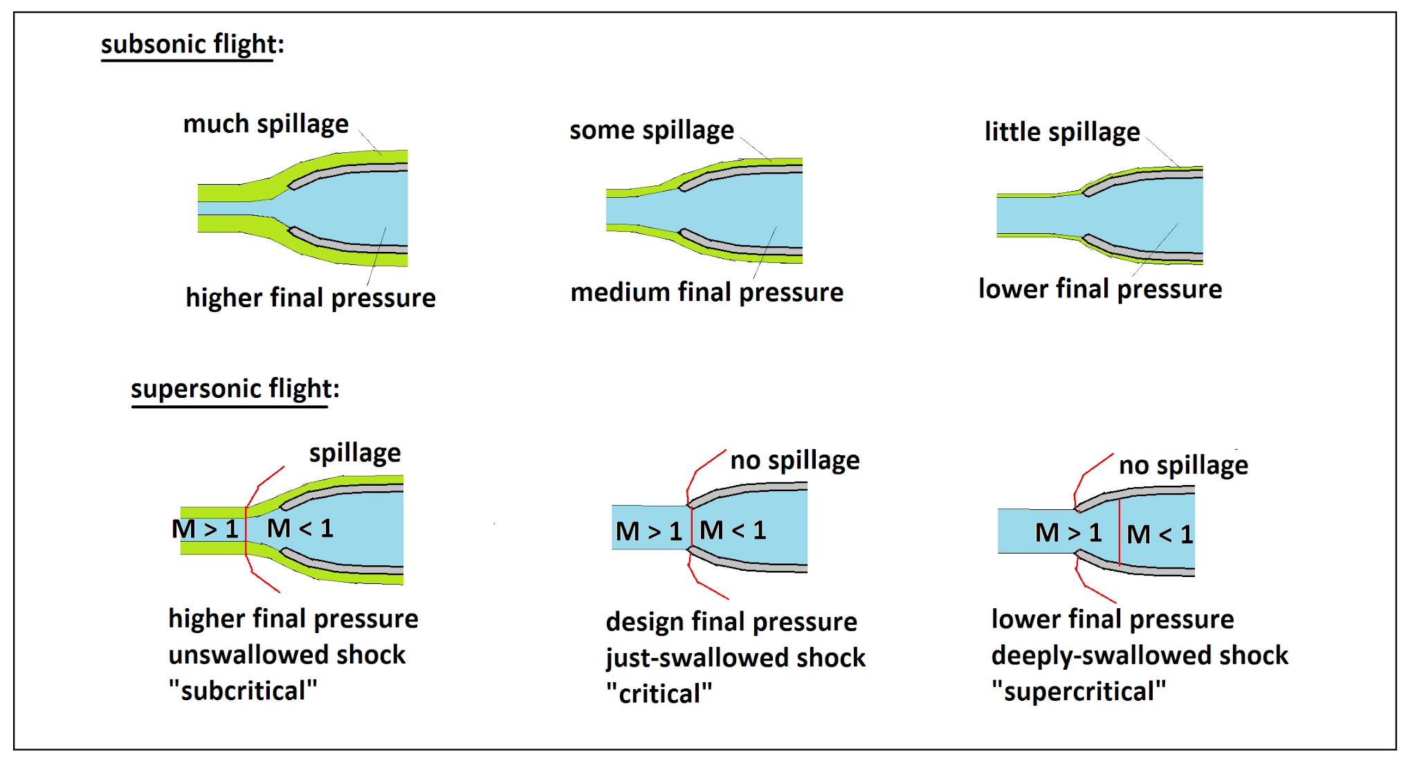
Intake throat area is the thing to measure for looking at performance vs mass flow rate and flight conditions. Throat is further downstream than the lips illustrated here.
See the image I used for my original intake capture area calculation. Su-57 is +23% compared to Flanker, +31% compared to F-22. If the drawings are not correct, then the values are also not correct, but at that time I took these for valid sources (are they from you paralay?). The ones you based your measurement on are, for the Su-57, quite low detail and I am not fully convinced. I guess the trick to get a more definitive value is to find and use proper blueprints.
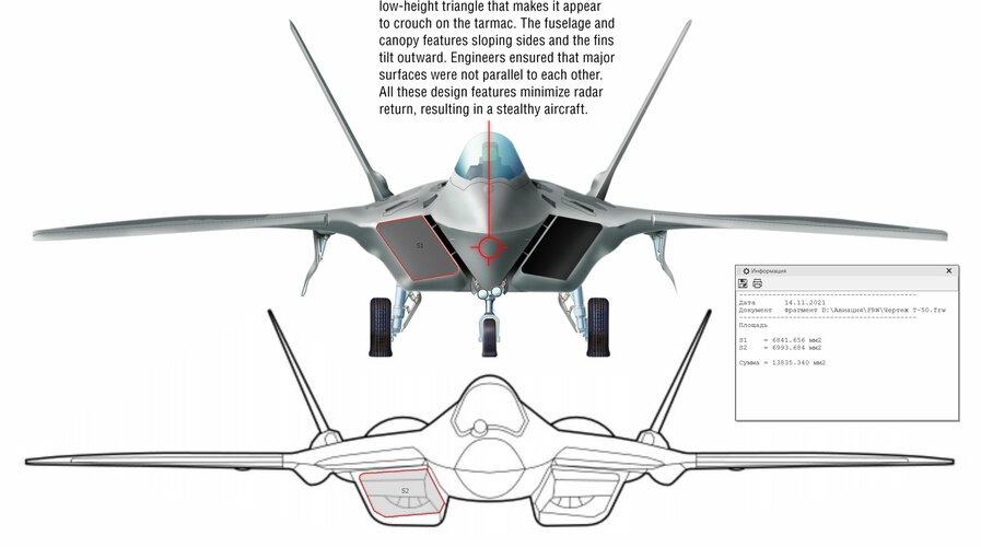
The image I used was directly from Sukhoi’s patent on the T-50, RU 2440916 from 2012, and the F-22’s image is directly from Lockheed Martin. The details and resolution are frankly adequate, and the image you posted is of a lower resolution. In any case, actual frontal capture area doesn’t truly reflect the mass flow, as the streamlines being captured by inlet isn’t necessarily normal to the plane as depicted. The size of the difference that you’re claiming isn’t demonstrated.
For the record, I still consider it not reasonable to deny that bigger intakes are motivated by a bigger mass flow consumption demand and don't see what those alleged very different design points between fighters with the same roles would be.
Again, the size of the difference you’re claiming hasn’t been demonstrated, and besides trying to measure capture area, what other evidence have you presented? Just to make it clear, the F-22 and Su-57 do not have the same roles, especially if you’ve read about the goals and intents of the PAK FA program, compared to the ATF.
Intake throat area is the thing to measure for looking at performance vs mass flow rate and flight conditions. Throat is further downstream than the lips illustrated here.
True, and the F-16’s larger inlet also increased critical Mach number. However, the Su-57’s inlet throat area is variable (it decreases as Mach number increases) so a direct comparison is difficult.
Intake throat area is the thing to measure for looking at performance vs mass flow rate and flight conditions. Throat is further downstream than the lips illustrated here.
Where is the air captured by those lips at atmospheric pressure going to go, other than into the throat and to the engine? That capture area is not designed to be spilling air all of the time.
The image I used was directly from Sukhoi’s patent on the T-50, RU 2440916 from 2012, and the F-22’s image is directly from Lockheed Martin. The details and resolution are frankly adequate, and the image you posted is of a lower resolution.
I posted because you questioned the values I got and I wanted to be transparent, I don't know for sure what the actual capture area is and never have claimed that I had official values. The image at the patent is a scarcely detailed schematic, not a blueprint. Maybe it is accurate re. the intake area, maybe not. Then there is the scaling and then the image from Lockheed, which seems rather ok but I have also not checked it in depth. After seeing so different values coming from you vs. the ones I measured, I would like to have very good graphical material before feeling that the question has been settled.
In any case, actual frontal capture area doesn’t truly reflect the mass flow, as the streamlines being captured by inlet isn’t necessarily normal to the plane as depicted.
What is the deviation you are suggesting? The plane will normally fly with a very small AoA so this looks like splitting hairs, but at most it would only increase the effective capture area of the intake vs. the frontal views we are taking.
My original argument was against the usual, tiresome claims about the propulsive shortcomings of the Su-57 vs F-22, trying to show that the known data indicate exactly the opposite. Since then and to be very honest with you, I have perceived you essentially denying and watering down every argument I make, not out of technical perfectionism (since some of these arguments are quite obvious to see) but out of some very evident bias. Your own measurements have also reported bigger capture area in the Su-57, plus higher reported thrust in the izd. 30, plus variable vs. fixed intakes. To you this does not prove anything about eventual propulsive advantages of the Su-57 and is due to "other" reasons. To me this is denial and is making me lose the faith in your good will to discuss further. The data are there, think what you want and as said already many times to many other people, let us wait for time and facts to settle the discussion.
Izd. 117S has 0.932 m diameter not frontal area, do not know what other engine you refer in the first line? And that has still does not say the whole story about the capture area of the intake...
LMFS, you have made a technical claim based on extremely flimsy foundations.
Qualified engineers with vastly more knowledge in this area than you dispute your methodology and conclusions. Your own words indicate to me you understand it less than I do, and I failed first year Aero Engineering and did an English degree instead.
The first very basic mistake you are making is that the amount of air entering the inlet at can be found by calculating the area of the intake lips.
Intake design is a good deal more complicated than you seem to think.
The streamtube is the blue in the diagram and represents the air actually ingested by the engine. At different speeds and altitudes, this can vary between a lot less than the physical intake area, to larger than the intake area. When you need less air, the extra air is spilled around the intake causing extra drag. So bigger isn't better, you want the intake designed for 'just right' at the intake design point. With a fixed intake, you accept poorer performance at off-design-point conditions. Variable intakes allow a greater range of efficient operation but add weight and may complicate stealth, but a fixed intake is likely adequate at supercruise speeds - its more Mach 2.0+ that needs variable intakes.
Rounded intake lips help the intake pull in extra air at low speed, but are not good in high speed flight, so other solutions might be needed. For example to increase effective intake area on the ground, blow in intake doors may be fitted to allow extra air in than the intake alone can allow.
As Steve says, the streamlines may not be normal to the intake, but have some angle not just on angle of attack but also depending on the aerodynamics around the intake - and an angle of entry alters the effective capture area.
You can't prove the intake area is significantly different. We need better drawings or someone with a tape measure to measure the intakes concerned. Throat area is the important measurement, not lip area (and variable intakes can vary throat area).
You can''t arbitrarily attribute a difference in intake inlet size (if proven) to a specific technical reason. The F-16 intake was deliberately oversized to allow for growth to a higher mass flow rate engine if needed for example. Supersonic fighters typically have their greatest demand for air at takeoff (hence blow-in doors) and typically constrict intakes and bypass air around the engine. If the Su-57 intakes are oversized you could argue this was to increase takeoff thrust, not supercruise thrust.
Variable intakes vary capture area and often include bleed bypass ducts to send excess air around the engine directly to the nozzle (e.g. F-4, A-5).
We don't know the mass flow rate of either of the Su-57 engines, and figures for the F119 are pretty variable and not proven.
Steve is trying to show you that designing intakes is far more complex than you seem to think, and given all the unknowns and variables your arguments are naïve and unprovable.
Steve isn't saying that the intake for the Su-57 is worse than the F-22's intake for supercruise. He isn't saying the Izdeliye 30 won't have a higher mass flow rate than the F119. It might well do, if the thrust figures bandied about are accurate. Its even possible an Su-57 could be better in supercruise with Izdeliye 30 than an F-22 with F-119. We just don't know enough to make a conclusion, and measuring intake sizes on drawings of unknown accuracy is not a method to come to conclusion.
You seem unable to accept this. This is not Steve's problem.
1. I never told this was a proven topic, since we don't have many cardinal data from both Su-57 and F-22, just that the hints pointed out to a higher mass flow consumption on the izd. 30, given higher thrust (almost obvious) and huge intakes as per my original measurements.
2. Other people were making technical claims putting the Su-57 down on much more flimsy foundations or simply ignoring facts. But they don't face nearly as much backlash as I did for stating common sense.
Qualified engineers with vastly more knowledge in this area than you dispute your methodology and conclusions. Your own words indicate to me you understand it less than I do, and I failed first year Aero Engineering and did an English degree instead.
With all due respect, nothing of what you say below is new to me. You seem to be taking me for someone that does not know what spillage is or the vast effects of speed, air density and engine rpm on airflow availability and consumption. That is not the case.
What I am saying is very simple and I still find it difficult to understand, why so much resistance to at least accept it as a reasonable possibility: the design of the intake is sized to suit the air consumption of the engine, it does not make sense to design it so it is going to be creating a lot of spillage 99% of the time and slash your flight range. So yes I do think that, within certain tolerances, the intake sizing of planes with similar flight regimes (both F-22 and Su-57 are direct rivalling air superiority fighters and supercruisers of the same generation) does give a decent indication of their mass flow consumption
Also said that max thrust is a reasonable (not exact but applicable within same generation and similarly tasked engines) indication of such mass flow, which is also rather logical, this was also disputed because of second and third order effects. Fine, we will see if izd. 30 is the first engine in the world that does not increase both TIT and OPR compared to its predecessor. These are OBVIOUS ways of improving an engine and they work together, the higher the compression, the more airflow you can admit and also the higher the temperature rise is, so your engine needs to have more temperature tolerance. The basic principle is not too complex , unless you want to make it look complicated
With a fixed intake, you accept poorer performance at off-design-point conditions. Variable intakes allow a greater range of efficient operation but add weight and may complicate stealth, but a fixed intake is likely adequate at supercruise speeds - its more Mach 2.0+ that needs variable intakes.
Makes you wonder what the design point of the Su-57 is, when they state in the patent that this type of intake is designed for flight between 2 and 3 M
As Steve says, the streamlines may not be normal to the intake, but have some angle not just on angle of attack but also depending on the aerodynamics around the intake - and an angle of entry alters the effective capture area.
I don't see why me saying the Su-57 "may" have higher air flow needs to be proven, but your flow field "may" not be normal in Su-57 and F-22, changing completely the effective capture area, doesn't.
I provided my values and hypothesis and (naively?) expected people to contribute in finding the best values and explanations possible (i.e. being constructive), not to invest their effort in destroying them first and foremost, before even checking and without feeling the need to construct plausible alternative explanations. But I think with a little work (and time) this question can be clarified sufficiently for those who have interest.
You can''t arbitrarily attribute a difference in intake inlet size (if proven) to a specific technical reason. The F-16 intake was deliberately oversized to allow for growth to a higher mass flow rate engine if needed for example.
It is an hypothesis, and one that makes sense at least, vs. "they did the intake big for the sake of spillage". I bet you many engine specialists here could give you a reasonable estimation of mass flow for a 18 tf engine with current technology, if they would want to.
Steve is trying to show you that designing intakes is far more complex than you seem to think, and given all the unknowns and variables your arguments are naïve and unprovable.
I know that the full propulsive design of a fighter is infinitely more complex than what we are discussing here, but he is rebutting first order approximations and general common sense with third order effects, and that is easy to notice.
Supersonic fighters typically have their greatest demand for air at takeoff (hence blow-in doors) and typically constrict intakes and bypass air around the engine. If the Su-57 intakes are oversized you could argue this was to increase takeoff thrust, not supercruise thrust.
Well, that is why blow-in doors exist (Su-57 has them too), to avoid oversizing the intakes for regular flight. No need to spoil 99% of the flight time for the 1% take-off needs
This discussion at present is pointless to continue in the current form, and is polluting this general SU-57 topic much like the RCS one before. I will try to prune it out from this topic into a dedicated topic today. Please refrain from further posts in this topic on this subject until this new topic is created.
Wait, so what is the exact purpose of the bleed grilles underneath the Intakes on Flanker and Su-57 compared to the side mesh screens of the intakes..?
To me it looks like the grilles under is to optimise subsonic air ingestion/airflow(you clearly see them flipping about on videos in subsonic flight), and the the side mesh screens are some sort of airbleed system for Supersonic flight
There seems to a basic misunderstanding on engine airflow and performance characteristics.
The design of the engine Fan / Compressor has an intrinsic airflow characteristic. When you are turning the engine at it maximum RPM (more on that later), it is flowing it's rated airflow - at sea level static (SLS) conditions (14.7 psia, 59F). When you change the inlet pressure by changing altitude and Mn, the actual airflow changes. Cut the inlet pressure in half, the actual airflow and thrust is cut in half, all else being equal. This is why engine designers use what is called corrected airflow. Take an engine that has a SLS airflow of 250 lbs / second, and take it to 40K, 0.8M the inlet pressure will be 4.15 psia - the actual airflow will be 70.5 lbs / second, but the corrected airflow is still 250 lbs / second. This relationship also applies to the function of the airframe inlet. The corrected airflow is how you compare inlets and engines at various flight conditions.
The other correction factor is inlet temperature. Theta (θ) is the ratio of the absolute inlet temperature (degrees R) divided by standard day temperature (59F + 460 = 519R).
Corrected RPM = Indicated RPM / √θ The higher the inlet temperature, the slower the corrected RPM.
Airflow of the engine remains the same for the same corrected RPM. So the RPM of the engine must increase as inlet temperature increases to maintain the same airflow.
Most engines are designed to operate around what is called the Theta break temperature. When the engine is operated below the Theta break temperature, they run at a constant corrected RPM at full rated corrected airflow. As the inlet temperature decreases below this level, the indicated RPM decreases as well as the turbine inlet temperature. You could try to raise indicated RPM in this cold condition, but the compressors will not flow significantly higher corrected flow before the efficiency and stall margin drops off and the flow becomes choked. As the inlet temperature increases, indicated RPM and turbine temperatures increase until they reach their design limits - this is the Theta break inlet temperature. With further increase in inlet temperature, indicated RPM and turbine temperatures remain constant at their limit, while corrected RPM, airflow, and thrust all drop below their rated values. Most fighter engines have a theta break inlet temperature of 60-70F, making full rated thrust a SLS standard day conditions.
At high altitude subsonic conditions, the cold air will have the engine operating at full corrected RPM and airflow at Mil or Max power, and the inlet has to be sized to provide this airflow under moderate ram conditions to avoid being a airflow restriction. At very low speeds and high angle of attack, air has difficultly turning into the inlet and airframe inlet does become a restriction, lowering the pressure at the inlet of the engine. Auxiliary inlet passages can increase airflow and thrust in these conditions.
With increasing supersonic speed, inlet ram recovery increases both inlet pressure and temperature. Once the engine reaches the theta break inlet temperature, the corrected airflow of the engine will decrease, even while the increased pressure is increasing the actual airflow. The supersonic inlet design has to be matched with engine corrected airflow characteristics (decreasing with increased Mn and temperature). This is done with sizing, variable inlet ramps, and inlet bypass doors. If the inlet is delivering more air than the engine can accept, the backup of air tends to push the inlet shock wave(s) forward out of the inlet, greatly reducing pressure recovery (inlet unstart). This can also result in an unstable condition where the inlet shock wave is repeatedly expelled and then re-ingested, which is a potentially damaging condition called inlet buzz.
There is a theoretical maximum inlet pressure recovery for each Mn condition, but each shock wave results in loss of some of that potential pressure, with that loss converted to increased temperature. A normal shock inlet like the F-16 works well up to 1.5M, then the losses build until the engine can't push the aircraft much past 2.0M, even though the same engine can push an F-15 with a variable ramp inlet to 2.5M. Fixed ramp inlets can be optimized for higher Mach number pressure recovery, but they too become inefficient as Mn increases beyond their design point.
The point being that the inlets are designed to maximize the pressure recovery at their design speed, but they can only minimize the pressure loss from the theoretical pressure recovery. They cannot increase the pressure higher than that theoretical maximum just by being made larger.
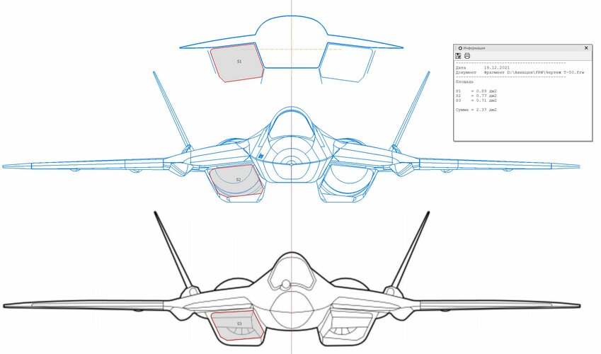
In my last measurements I get ca. 10% more capture area in the Su-57 than in the F-22:
- Using the patent and Lockheed drawings, since photos always carry distortion
- 14.1 vs 13.6 m wingspan
- 0.74 vs 0.67 sqm capture area
I cannot comment on whether this is an accurate measurement, just provide the conditions I used, in case anyone wants to check out.
I like this approach because I have always sensed that the only half reasonable way to understand the propulsive performance of the Su-57 (actual or potential I don't know) was through the intake design, that determines the mass flow supply to the engine and is at least a tangible element of judgement, unlike hearsay and dubious sources. All the rest being equal, +10% airflow re. a ca. 16 tf engine (F119) would mean 17.6 tf, which is frankly close to the values commented for the izd. 30, so maybe this is not so far off. My original +30% estimation probably came from a distorted drawing and I think it was exaggerated.
@F119Doctor
Many thanks again for explaining all these concepts and how they relate to each other. There are many competing effects related to temperature, speed and altitude in engine performance and which is the dominant one in each case is not trivial to discern
My comments and questions, based on this and the previous discussions, just in case you feel like providing some further insight:
> Considering ram compression, it seems clear that the airflow will increase with the increasing speed and that ultimately the turbine temperature would limit the RPM and airflow, yet what we see is that intakes are frequently designed for the max Mn in supersonic fighters. Is this related to the decreasing pressure recovery of the intake maybe?
> Corrected airflow seems to be the airflow that the engine or inlet would have at SLS and standard atmospheric conditions with the current RPM, right? How does it relate to actual thrust? It seems thrust depends on actual airflow instead
> Is the theta break inlet temperature of a supercruising fighter different to that of a more conventional one?
> Increasing inlet pressure thru ram recovery by itself does not increase RPM and turbine temperature by itself. If you doubled inlet pressure at the same temperature, you would have double the airflow with all the internal pressures doubled, fuel flow doubled, and thrust doubled (ignoring any nozzle pressure ratio effects), all with the same internal temperatures. At very low inlet pressures (upper left corner of the envelope) this relationship breaks down due to Reynolds number effects, and at very high inlet pressures (lower right corner) the combustor area pressures can reach the burst limit of engine and the control system will cut back fuel flow (lower RPM and airflow) to limit that burner pressure.
> Thrust = Airflow. Basically correct below the Theta Break. Above the Theta break, airflow is reduced, but the engine OPR, EPR, and NPR are all reduced meaning thrust falls faster than airflow.
> At 40K, 1.5M the inlet conditions are approximately 12 psi, 100F. If you want to maintain engine thrust at these conditions, raising the Theta break temperature is highly beneficial. The engine needs sufficient rotor speed and temperature margin above standard day conditions to achieve this.
What is the deviation you are suggesting? The plane will normally fly with a very small AoA so this looks like splitting hairs, but at most it would only increase the effective capture area of the intake vs. the frontal views we are taking.
It’s not simply a matter of alpha, but also local aerodynamic effects such as those from the forebody. These aren’t values that are easily quantified just by simple visual analysis.
Since then and to be very honest with you, I have perceived you essentially denying and watering down every argument I make, not out of technical perfectionism (since some of these arguments are quite obvious to see) but out of some very evident bias…To me this is denial and is making me lose the faith in your good will to discuss further.
To be very honest with you, you’ve demonstrated a poor understanding of the propulsion principles that you are arguing so emphatically about. You are completely focused on correlating supercruise performance with mass flow and inlet sizing, despite so many sources and publications indicating that that’s not the case.
Other people were making technical claims putting the Su-57 down on much more flimsy foundations or simply ignoring facts. But they don't face nearly as much backlash as I did for stating common sense.
…
What I am saying is very simple and I still find it difficult to understand, why so much resistance to at least accept it as a reasonable possibility: the design of the intake is sized to suit the air consumption of the engine, it does not make sense to design it so it is going to be creating a lot of spillage 99% of the time and slash your flight range. So yes I do think that, within certain tolerances, the intake sizing of planes with similar flight regimes (both F-22 and Su-57 are direct rivalling air superiority fighters and supercruisers of the same generation) does give a decent indication of their mass flow consumption
…
I know that the full propulsive design of a fighter is infinitely more complex than what we are discussing here, but he is rebutting first order approximations and general common sense with third order effects, and that is easy to notice.
Airflow demand of the engine is not just at supercruise conditions. Again, inlet sizing is driven by worst case scenarios that demand maximum capture area, such as takeoff or maximum Mach; this was even demonstrated with data from the F-15, which you then handwave away as not applicable since it’s not a supercruising aircraft. Well, the propulsion principles don’t change, and in any case the afterburner is downstream of the turbines and its operation doesn’t affect airflow demand.
All inlets deal with spillage. A design may consider an increase in spillage worthwhile if it has benefits in other parts of the envelope. We just don’t know.
You keep using “common sense” to try to explain your argument, but frankly it looks like argument from incredulity; trying to correlate supercruise performance with inlet size in a linear cause-and-effect manner when that’s not how the inlet design process is.
In an external compression inlet, the terminal shock occurs in front of the throat. The throat area can be an indicator of mass flow, but variable geometry inlets can vary the throat area, and this area constricts as Mach number increases, making direct comparisons difficult. Aside from variable ramps, the shock position can also be controlled using pressure means.
A inlet with variable capture area and throat area like the F-15 would grant even greater flexibility.
I like this approach because I have always sensed that the only half reasonable way to understand the propulsive performance of the Su-57 (actual or potential I don't know) was through the intake design, that determines the mass flow supply to the engine and is at least a tangible element of judgement, unlike hearsay and dubious sources. All the rest being equal, +10% airflow re. a ca. 16 tf engine (F119) would mean 17.6 tf, which is frankly close to the values commented for the izd. 30, so maybe this is not so far off.
Again, evaluating propulsive performance through inlet capture area is pointlessly simplistic, especially without understanding all of the design considerations. I’m not stating that the Su-57 has better or worse supercruise performance one way or another. As Paul said, there isn’t enough information to draw a conclusion, whereas you seem to have your mind set using poor foundations.
As a side note, the patent drawings is of the T-50 prototype, or the “first stage” airframes, which have a wingspan of 13.95 m. The “second stage” production airframes have slightly increased wingspan of 14.1 m. Inlet capture area of both the Su-57 and F-22 are around 0.7 sqm; again, given all the functions of the inlet and local flow field effects, I wouldn’t consider the difference to be worth nothing.
If you are trying to judge the supercruise potential of a turbofan engine, a better place to start would be to assume that the airframe designers have made their best efforts to match the flow characteristics of the engine and maximized pressure recovery at their desired flight conditions.
Instead, you can look at the fan cross section and estimate the reduction in flow area from the inlet to the exit of fan. In typical fan/compressor design, this flow area ratio will be proportional to the fan pressure ratio (FPR) at the design max airflow, with the airflow Mach number remaining relatively constant from front to back. You need a high FPR to achieve the high EPR and NPR necessary for the exhaust velocity needed for supercruise thrust.
The highest FPR I have seen published in the open is 4.2 for the EJ200. The cross section of the 3 stage Fan for the ALF31-M3 shown above, if accurate, does not appear to contract fast enough to support a pressure ratio that high.
Sorry that I have not been able to follow the Russian engine designation progression to tell if the ALF31-M3 is the IZD-30, or if anyone has published an accurate IZD-30 cross section.
> At 40K, 1.5M the inlet conditions are approximately 12 psi, 100F. If you want to maintain engine thrust at these conditions, raising the Theta break temperature is highly beneficial. The engine needs sufficient rotor speed and temperature margin above standard day conditions to achieve this.
Interesting, that would surely imply that the engine may not have the same performance in other points of the envelope like subsonic acceleration as it may have been with other design temperature, maybe the FPR cannot be as high as in other designs? Would a VCE address that issue, allowing different FPR for different bypass ratios?
Sorry that I have not been able to follow the Russian engine designation progression to tell if the ALF31-M3 is the IZD-30, or if anyone has published an accurate IZD-30 cross section.
The FM3 is a modern variant by Salut of the Lyulka-Saturn AL-31F, but it has the same layout and basic characteristics. The izd. 30 is a totally new Lyulka design with a different layout (there were some references to stage count but I am unsure if they are official) and that will be the base for the new family of Russian military engines. No diagram has ever been published that I know.
You are completely focused on correlating supercruise performance with mass flow and inlet sizing, despite so many sources and publications indicating that that’s not the case.
You misrepresent what I say. I just claimed that the Su-57 was piling one element of supercruising performance on top of the other, among them the intakes being variable and bigger possibly allowing to ensure more airflow even at high supersonic speeds and high altitude, you decided that I was wanting to prove the direct correlation about the size of the intake and the thrust without considering other effects, maybe because that would allow you to skew the discussion away from the hardly disputable arguments I was making. I did not see you pursuing the same way all the guys making frivolous claims about the poor propulsion of the Su-57.
Since I am supposed to demonstrate every single statement I make, how about you demonstrating that high supersonic flight at max dry setting is not a design point of the intake and engine of Su-57 and F-22? Supercruising is an EXPLICIT design goal of both the Su-57 and the izd. 30 and in fact, the reason why AL-41F1 is not considered enough. Or do you expect they would design the izd. 30 if the mil thrust of the izd. 117 was enough? On top of that, max speed of 5th gen fighters seems to be quite low in comparison with 4th gen designs, so it indeed seems reasonable to think that the max speed in dry settings instead of max Mach on AB is a more relevant design point.
All inlets deal with spillage. A design may consider an increase in spillage worthwhile if it has benefits in other parts of the envelope. We just don’t know.
You prefer not to make any hypothesis about it, that is your decision but not mine. It is not so hard to understand what they try to achieve with the plane, the general requirements for a modern air superiority fighter are rather predictable and many of them have been stated in great detail in the plane's description and in the patents. You allege unknown design requirements that you may want to detail?
You keep using “common sense” to try to explain your argument, but frankly it looks like argument from incredulity; trying to correlate supercruise performance with inlet size in a linear cause-and-effect manner when that’s not how the inlet design process is.
You are stretching it and you know it. I am saying that a bigger intake is a reasonable hint of a higher mass flow consumption of the engine, as a first order approximation, and suggested that the apparent strong overdimensioning may be an additional measure to help keeping a very high thrust at very high altitudes. Further corrections of our estimations of the capture area bring it to a much smaller size that may not require such explanation, agreed.
In an external compression inlet, the terminal shock occurs in front of the throat. The throat area can be an indicator of mass flow, but variable geometry inlets can vary the throat area, and this area constricts as Mach number increases. Aside from variable ramps, the shock position can also be controlled using pressure means.
A inlet with variable capture area and throat area like the F-15 would grant even greater flexibility.
Still don't know what that has to do with the fact that the air captured by the intake will go to the throat but for the boundary layer extraction and eventual bleed doors (which I don't see clearly in the Su-57 intake).
Again, evaluating propulsive performance through inlet capture area is pointlessly simplistic, especially without understanding all of the design considerations
You can work on scenarios based on requirements from similar planes, that would be the logical thing to do. In any case I am not surprised that a Western guy does not want to actively participate in making the case for the Su-57. I already know your opinion, so be it.
The inlets have a design Mach number for optimal pressure recovery, but capture area sizing is not solely driven by that condition, and in any case, it’s area ratios and ramp angles, not area, that determines pressure recovery. Matching flow conditions require information we just don’t have. Again, the sizing of the inlet has to balance airflow demands in worst case conditions and design operating points. The tradeoffs are at the discretion of the designers, and we don’t know what they are to draw a conclusion; however, there’s simply nothing so far to show that supercruise conditions are the worst case scenarios demanding maximum capture area. Again, see capture area demand from the F-15. Pressure recovery is not the same as mass flow.
It is not an attack, at all, just that I am not surprised about your lack of motivation. I am pretty sure if you were tasked to produce an engineering assessment of the Su-57's propulsive capabilities and a couple reasonable estimates you would be capable of saying more than "no idea". But it is ok.
> At 40K, 1.5M the inlet conditions are approximately 12 psi, 100F. If you want to maintain engine thrust at these conditions, raising the Theta break temperature is highly beneficial. The engine needs sufficient rotor speed and temperature margin above standard day conditions to achieve this.
Interesting, that would surely imply that the engine may not have the same performance in other points of the envelope like subsonic acceleration as it may have been with other design temperature, maybe the FPR cannot be as high as in other designs? Would a VCE address that issue, allowing different FPR for different bypass ratios?
If two engines have the same mass flow and same FPR / EPR / NPR at a specific flight condition, they will have similar thrust at Mil Power. The engine with the larger core (lower BPR) with more rotor speed and temperature margin will likely be heavier and have worse SFC that the engine will a smaller, harder working core that doesn't have that margin. There are some second order effects with exhaust temperature (higher temp means higher thrust), but basically the thrust would be similar.
A VCE engine does address some of these issues, but remember you can't significantly increase the BPR by increasing total mass flow - if the intake is well matched to the engine flow it becomes the limiting factor. On a VCE, you increase the BPR by reducing the core airflow and lowering the FPR - both because the core is producing less power to drive the Fan, and to reduce exhaust velocity for better propulsive efficiency in the subsonic cruise condition. The VCE engine addresses the SFC challenge of a supercruise engine, but you are still stuck with the weight of the large core module necessary for the supercruise performance.
IF you can increase the temperature margin of the turbine thru materials & cooling design, and you can build rotor speed capability with new materials and structural design, you can still have supercruise performance with a smaller core capable of driving a high PR fan with a higher BPR. All the engine companies are trying to make this happen, but that is a very big IF.
A VCE engine does address some of these issues, but remember you can't significantly increase the BPR by increasing total mass flow - if the intake is well matched to the engine flow it becomes the limiting factor.
I had heard that one of the main advantages of the VCE is that it allows to significantly reduce spillage at subsonic cruising speeds, wouldn't that go counter to what you say?
IF you can increase the temperature margin of the turbine thru materials & cooling design, and you can build rotor speed capability with new materials and structural design, you can still have supercruise performance with a smaller core capable of driving a high PR fan with a higher BPR. All the engine companies are trying to make this happen, but that is a very big IF.
That is I think the key question re. izd. 30. Given the information provided by Marchukov (highest specific thrust + roughly same SFC of AL-31F which is ca. 0.67), what do you think is more feasible, to achieve that in a fixed bypass ratio engine or in a VCE? What do you make out of that, do you see it possible when the references are F119 and F135, both being 5th gen engines and the later specifically running substantially hotter than any known engine? On the one hand, the VCE option implies several technological difficulties and a higher technical risk but would be the logical, long term solution to the problems of supersonic cruising, on the other a fixed BPR would demand a very substantial and unlikely leap by Russian designers to go beyond the specific thrust of F119 as a low BPR engine and keep a SFC that is broadly considered equivalent to that of the F135. On top of that come the claims about TWR that you already referred as difficult to believe for a supercruising engine... do you make some sense of the data provided until now? Would you have some OPR, TIT and mass flow estimates for such an engine?
I cannot answer your questions regarding OPR, TIT, or mass flow.
To reduce the weight on a supercruise capable engine, I think that TI matrix composites will be necessary to build compressor rotors without the heavy center bores. Turbine rotors (heavy nickel alloy) is another challenge. Increasing TIT may require ceramics to get significant increased temperature capability. All of these things have been discussed as possible advancements, but I don’t know if anyone has successfully produced and tested these.
Another limitation is how hot you can get the combustor flame. When you get to stoichiometric F/A ratios, that is as hot as you can go. Increased OPR is needed to gain cycle efficiency with the higher TIT, but compressor efficiency, stage counts, and compressor exit temps limit how far you can push this. Rotating detonation combustion may be the way around these limitations.
Back to the subject of the Su-57 intake design, one of the interesting aspects of supercruise design is how you slow down.
When the F-15 was developed with the F100 engine, inlet buzz could occur when the engine was throttled down from Mil/Max power, reducing the engine airflow below the inlet design point, even with the variable capture capability of the inlet. To prevent this from occurring, the engine was programmed to raise Idle speed to Mil power above 1.4M. This schedule ramped down to regular flight idle at 0.85M. Since the aircraft could not supercruise, bringing the throttle to Idle would cancel AB and the aircraft would slow down. This same minimum airflow scheduling was also used on the F16.
However, if you used this scheme on a aircraft supercruising above 1.5M, how would you ever slow down if the engine was prevented from slowing down below Mil power? You would have to apply sustained G loading to bleed enough energy just to slow down.
On the F-22, the inlet bypass louvers on the top of the airframe can open to allow the intake airflow to remain high enough to prevent this inlet instability while the engine reduces its airflow and thrust sufficiently to slow the aircraft down.
I don’t see this type of inlet airflow bypass in the Su-57, unless the auxiliary inlets under the variable ramp section can function in this capacity at supersonic speeds. This might imply a lower supercruise target speed for this design, perhaps in the 1.2-1.3M range. This also would lower the inlet temperature to the engine, making a high Theta break less important.
I don’t see this type of inlet airflow bypass in the Su-57, unless the auxiliary inlets under the variable ramp section can function in this capacity at supersonic speeds. This might imply a lower supercruise target speed for this design, perhaps in the 1.2-1.3M range. This also would lower the inlet temperature to the engine, making a high Theta break less important.
Have you ever wondered why the Su-57 has a large sweep wing, 48 degrees? This is more than any other fighter
The Russian Air Forces required a cruising speed of M>1.78 (1900 km/h) from a fifth-generation fighter
That is interesting. None of currently known supercruising fighters (in the "light" sense of the word i.e. cruise supersonically even when below 1.5 M), that is, Su-35, Rafale, Eurofighter and quite probably Su-57 with the current engine, seem to have those louvers you mention in the F-22.
When the F-15 was developed with the F100 engine, inlet buzz could occur when the engine was throttled down from Mil/Max power, reducing the engine airflow below the inlet design point, even with the variable capture capability of the inlet. To prevent this from occurring, the engine was programmed to raise Idle speed to Mil power above 1.4M. This schedule ramped down to regular flight idle at 0.85M. Since the aircraft could not supercruise, bringing the throttle to Idle would cancel AB and the aircraft would slow down. This same minimum airflow scheduling was also used on the F16.
First question would be whether this buffeting issue applies to other planes with other intake layouts in the same way
The other, whether the speed that was scheduled for the F-15 applies to other designs.
I could imagine a supercruising plane (at least this should apply to current designs except F-22) progressively reducing thrust from mil (in the amount compatible with the intake's design) would slow down the plane by not only reducing thrust but also increasing spillage. That would slow the plane down and reduce ram gain, allowing further reduction of the engine's RPM wouldn't it?
However, if you used this scheme on a aircraft supercruising above 1.5M, how would you ever slow down if the engine was prevented from slowing down below Mil power? You would have to apply sustained G loading to bleed enough energy just to slow down.
On the F-22, the inlet bypass louvers on the top of the airframe can open to allow the intake airflow to remain high enough to prevent this inlet instability while the engine reduces its airflow and thrust sufficiently to slow the aircraft down.
Can't other features like the variable ramps or the resonant design of the intake and air duct itself prevent buffeting too?
Also, there were other non-supercruising planes with bypass doors (F-14 for instance if I am not wrong), what was the reason for them? Maybe requirements for high speed at low altitude?
I don’t see this type of inlet airflow bypass in the Su-57, unless the auxiliary inlets under the variable ramp section can function in this capacity at supersonic speeds. This might imply a lower supercruise target speed for this design, perhaps in the 1.2-1.3M range. This also would lower the inlet temperature to the engine, making a high Theta break less important.
From the patent RU 2472956, maybe such solution is already present?
Stable operation of the air intake in all flight modes and engine operation is provided due to the presence of an air bypass in oblique jumps of the seal 28, a system for draining the boundary layer in the form of perforations on the stages of wedges 7 and 20 of the braking system and a transverse gap 13 between the front 11 and rear 12 adjustable panels. Draining of the boundary layer is additionally possible through an additional transverse slot, which is regulated by the flap 21 and located in the throat area behind the stationary braking wedge 20, which contains unregulated steps.
Interestingly, there have been design modifications to those additional inlets you mention during the development process, not clear if for RCS reasons or otherwise. It is also unclear whether they can operate as air bypass, though that function is not stated in the patents that I have seen.
We have not seen the Su-57M yet, so we cannot be 100% sure of how this issue will be solved with the second stage engine yet.
Question: wouldn't a VCE allow to address this issue by increasing the BPR? That may be a more elegant way to handle engine bypass than additional louvers
As to the hypothesis that the Su-57's design goal is a low supercruising speed, why it does not look likely to me:
- First, it is a both logical and also explicitly stated goal that the requirement for the PAK-FA was to at least match or surpass the (way older) F-22. Otherwise the development is failed from the beginning and therefore pointless.
- Why the variable ramps which start making sense from 1.5 M onwards and are a serious challenge to be designed with low RCS? You can see the considerable complexity of the design in patent mentioned above and also RU 2460892
- Why the new engine, specifically for supercruising, when the first stage one already allows for low supersonic speeds? (Supercruising, without further details, has been confirmed for the current engine by program officials)
- Why the highest specific thrust of any comparable engine?
- How can an engine with 12-15% more max thrust (hence higher mass flow in all likelihood) and higher spec. thrust not have higher mil thrust too than F119 (both uninstalled and at operational conditions, when it also has a more efficient variable intake?)
- Su-57 in the first stage has already been compared to Su-35 as accelerating much faster and going in supersonic regime almost without the pilot noticing (indicates both clearly higher excess power and higher supercruising capabilities than Su-35). Besides supercruising being one of the cardinal design requirements as stated in patents and other official documents (see below, "the T-50 is not inferior to the 5th generation F-22 aircraft as on subsonic, and at supersonic speeds")*. Hence its drag should be specially optimised and is difficult to justify that having more thrust it would be way slower.
* If some Russian speaker could help with the content of the slide it would be appreciated, some parts as from Yandex translation do not make sense
@paralay
Did Pavel Bulat provide some insights or estimations for izd. 30? I think he did deliver something for izd. 117 around 125-128 kg/s wasn't it?
BTW I found this quote by Marchukov, March 2016:
The general designer emphasized: "The Phase II engine designed for the PAK FA
is a Generation 5+ design, even a Generation 5++ one." The engine is 15-20%
superior to the previous ones in terms of specific characteristics.
"The engine’s characteristics have been refined through a sharp improvement in
the operating cycle parameters, efficiency of units and introduction of advanced
technologies and materials in the first place. It features higher thrust and a
sizeable reduction in specific fuel consumption in virtually all operating modes, i.e.
not only in the cruising range mode, but in the acceleration and afterburning
modes as well - the modes the aircraft is normally flown in. This implies a life cycle
cost reduction," the general designer explained. "In addition, a hefty specific
weight reduction through advanced technologies and materials has been planned."
Supersonic cruising flight
The experimental work carried out allows us to consider the aerodynamic characteristics of the T-50 one of the best in its class. The T-50 is not inferior to the fifth-generation F-22 aircraft at both subsonic and supersonic speeds, and surpasses the "four plus" generation aircraft at supersonic speeds
large fuel reserve in internal tanks and supersonic cruising flight of the T-50 to respond quickly to threats
Persistence in supersonic flight and speed level are both the enabling elements allowing to fulfil the stated tactical goal of quickly reacting to threats. Hence the highly developed integral aerodynamic layout (very wide fuselage) and wide chord wings with big internal fuel capacity) and second stage engine with vastly improved capabilities over the already supercruising capable izd. 117
Adding further detail, Strelets said that the standard flight regime of the plane was supersonic, from take-off to landing. Therefore and in order to obtain meaningful combat radius (operation up to ca. 500 km in the enemy rear as per knwon references to the plane's TTZ), the fuel tanks of the plane need to be dimensioned accordingly. Probably the range of the plane in supersonic flight is not far from that of the MiG-31
The fan "izd. 30" is called "izd. 129", one can timidly assume an air consumption of 129 kg/sec
The weight of the internal fuel T-50 is at least 9000 kg (according to 3-D modeling) or 10100 kg (according to an insider). The cruising flight speed according to the tactical and technical task is 1890 km / h, the flight time in this mode, according to the tactical and technical task is 1 hour. Therefore, the maximum flight range at supersonic speed is 1890 km (estimated) or 1500 km (according to Poghosyan)
By the way, the flight time of the MiG-31 at supersonic speed is no more than 15 - 30 minutes, while the speed is no more than 2500 km / h. Thus, we get a flight range of no more than 625 km - 1250 km in this mode
That is interesting. None of currently known supercruising fighters (in the "light" sense of the word i.e. cruise supersonically even when below 1.5 M), that is, Su-35, Rafale, Eurofighter and quite probably Su-57 with the current engine, seem to have those louvers you mention in the F-22.
When the F-15 was developed with the F100 engine, inlet buzz could occur when the engine was throttled down from Mil/Max power, reducing the engine airflow below the inlet design point, even with the variable capture capability of the inlet. To prevent this from occurring, the engine was programmed to raise Idle speed to Mil power above 1.4M. This schedule ramped down to regular flight idle at 0.85M. Since the aircraft could not supercruise, bringing the throttle to Idle would cancel AB and the aircraft would slow down. This same minimum airflow scheduling was also used on the F16.
First question would be whether this buffeting issue applies to other planes with other intake layouts in the same way
The other, whether the speed that was scheduled for the F-15 applies to other designs.
I could imagine a supercruising plane (at least this should apply to current designs except F-22) progressively reducing thrust from mil (in the amount compatible with the intake's design) would slow down the plane by not only reducing thrust but also increasing spillage. That would slow the plane down and reduce ram gain, allowing further reduction of the engine's RPM wouldn't it?
However, if you used this scheme on a aircraft supercruising above 1.5M, how would you ever slow down if the engine was prevented from slowing down below Mil power? You would have to apply sustained G loading to bleed enough energy just to slow down.
On the F-22, the inlet bypass louvers on the top of the airframe can open to allow the intake airflow to remain high enough to prevent this inlet instability while the engine reduces its airflow and thrust sufficiently to slow the aircraft down.
Can't other features like the variable ramps or the resonant design of the intake and air duct itself prevent buffeting too?
Also, there were other non-supercruising planes with bypass doors (F-14 for instance if I am not wrong), what was the reason for them? Maybe requirements for high speed at low altitude?
I don’t see this type of inlet airflow bypass in the Su-57, unless the auxiliary inlets under the variable ramp section can function in this capacity at supersonic speeds. This might imply a lower supercruise target speed for this design, perhaps in the 1.2-1.3M range. This also would lower the inlet temperature to the engine, making a high Theta break less important.
From the patent RU 2472956, maybe such solution is already present?
Stable operation of the air intake in all flight modes and engine operation is provided due to the presence of an air bypass in oblique jumps of the seal 28, a system for draining the boundary layer in the form of perforations on the stages of wedges 7 and 20 of the braking system and a transverse gap 13 between the front 11 and rear 12 adjustable panels. Draining of the boundary layer is additionally possible through an additional transverse slot, which is regulated by the flap 21 and located in the throat area behind the stationary braking wedge 20, which contains unregulated steps.
Interestingly, there have been design modifications to those additional inlets you mention during the development process, not clear if for RCS reasons or otherwise. It is also unclear whether they can operate as air bypass, though that function is not stated in the patents that I have seen.
We have not seen the Su-57M yet, so we cannot be 100% sure of how this issue will be solved with the second stage engine yet.
Question: wouldn't a VCE allow to address this issue by increasing the BPR? That may be a more elegant way to handle engine bypass than additional louvers
As to the hypothesis that the Su-57's design goal is a low supercruising speed, why it does not look likely to me:
- First, it is a both logical and also explicitly stated goal that the requirement for the PAK-FA was to at least match or surpass the (way older) F-22. Otherwise the development is failed from the beginning and therefore pointless.
- Why the variable ramps which start making sense from 1.5 M onwards and are a serious challenge to be designed with low RCS? You can see the considerable complexity of the design in patent mentioned above and also RU 2460892
- Why the new engine, specifically for supercruising, when the first stage one already allows for low supersonic speeds? (Supercruising, without further details, has been confirmed for the current engine by program officials)
- Why the highest specific thrust of any comparable engine?
- How can an engine with 12-15% more max thrust (hence higher mass flow in all likelihood) and higher spec. thrust not have higher mil thrust too than F119 (both uninstalled and at operational conditions, when it also has a more efficient variable intake?)
- Su-57 in the first stage has already been compared to Su-35 as accelerating much faster and going in supersonic regime almost without the pilot noticing (indicates both clearly higher excess power and higher supercruising capabilities than Su-35). Besides supercruising being one of the cardinal design requirements as stated in patents and other official documents (see below, "the T-50 is not inferior to the 5th generation F-22 aircraft as on subsonic, and at supersonic speeds")*. Hence its drag should be specially optimised and is difficult to justify that having more thrust it would be way slower.
All supersonic inlets have a maximum and minimum corrected airflow where they operate in a stable manner, with the shock waves properly positioned. The faster you go, the narrower spread between these values. For the F-15 and F-16, 1.4M was the speed where spread reached its minimum and the engine was maintained at Mil power to prevent dropping below that minimum corrected airflow. When the corrected airflow drops below the minimum, the normal shock is pushed forward out of the throat, and pressure recovery drops abruptly. With the pressure behind the throat decreased, the airflow in the inlet is momentarily increased, the shock is swallowed, pressure recovery increases, airflow drops below minimum, and the process repeats, many times per second. This is inlet buzz, and it can be very damaging to both the airframe inlet structure and the engine.
* Could another inlet design with variable ramps or capture area lower the minimum airflow required for stable operation in response to decreased engine airflow? I don't know, but it is possible - I am not an inlet designer.
* Why is this not a problem on other aircraft from minimal supercruise capability of 1.1-1.3M? Because they aren't cruising fast enough to reach the critical inlet Min / Max airflow Mn. Remember, the F-15 and F-16 will reduce power part way between Mil and Idle at these low supersonic Mn conditions.
* Why 1.5M? This is the lowest supercruise speed advertised for the F-22, and it is above the 1.4M point where F-15 / F-16 were prevented from reducing power below Mil.
* Are there other airplanes with bypass doors in the inlet. Yes - SR-71 for one had both forward and aft bypass systems to match inlet airflow requirements to the engine airflow for stable operation. If these did not operate as intended, inlet unstarts occurred (with too little flow) or high drag (too much airflow bypassed from the forward bypass, which vented overboard). On the F-22, I imagine that the bypass louvers do more than just allow the aircraft to slow down from supercruise.
* Draining or diverting (DSI inlet) boundary layer is a requirement for stable operation of supersonic inlets. However, boundary layer control by itself may not be enough to match inlet airflow requirements for stable operation with the engine airflow consumption under all conditions.
* Could a VCE engine address this issue? Quite possibly - you could transition from low bypass / high FPR mode for supercruise thrust to a high bypass / low FPR mode that would maintain engine airflow while reducing supersonic thrust.
* Until the Su-57 demonstrates its supercruise performance with the second stage engine, none of us knows if the stated performance claims are real or just aspirations
* FYI - you claimed the Su-57 a more efficient inlet than the F-22. While the F-22 inlet is a fixed geometry, I believe you can safely assume that it was designed to have the maximum possible pressure recovery in the supercruise speed range. The variable ramp inlet only has a significant advantage above 2.0M, which the F-22 can easily reach with its fixed intake and the Su-57 is limited from exceeding this substantially by airframe heating. During high altitude supersonic flight test, the F-22 would leave the F-15 chase planes miles behind, even though the F-15 has a higher advertised top speed.
I think that estimate is a bit low. On the one hand, the gain in thermal efficiency would need to be brutal to increase the thrust from 15 to 18 tf (20% increase) with the same airflow. On the other, the OPR of a supercruising engine is in the order of 35:1 (early supposedly official value for the F119), I do not think it is essentially wrong to take that as a basis value for the izd. 30 if it has higher specific. thrust than the F119, considering that the TIT is probably a bit higher (see roadmap below) and roughly in line with the F135 (which has a big reserve as per the reports). So IMHO a value around 140-150 kg/s is probably closer to the reality.
The weight of the internal fuel T-50 is at least 9000 kg (according to 3-D modeling) or 10100 kg (according to an insider). The cruising flight speed according to the tactical and technical task is 1890 km / h, the flight time in this mode, according to the tactical and technical task is 1 hour. Therefore, the maximum flight range at supersonic speed is 1890 km (estimated) or 1500 km (according to Poghosyan)
From what I read, the Su-57 is filled with fuel up to its ears, literally every usable space is fuel, in pictures for production it seems even the basis of the tails is sealed for that purpose. A natural design reference would be the fuel capacity of the Flanker, Su-57 has smaller linear dimensions but bigger surface and a more developed integral aerodynamic design, so it is not easy to estimate whether they reached or surpassed the 11.5 t of the Su-35. Those 10 t look reasonable to me, in the absence of a more definitive value.
Did you manage to see the TTZ or get reliable info about the cruising speed? And the range info from Pogosyan, is it sourced? Those are quite relevant pieces of information...
That supersonic range BTW is identical to the one stated officially for the MiG-31 (probably referred at the supersonic cruise speed of 2.35 M). One additional aspect where it seems apparent that Sukhoi tried to cover to a certain extent the interceptor role of the MiG with the Sukhoi (described as a strike plane, a fighter and an interceptor in one). Less fuel and less speed, but serious advantages in SFC, RCS level and agility at high speed and high altitude constitute serious arguments too.
* Could another inlet design with variable ramps or capture area lower the minimum airflow required for stable operation in response to decreased engine airflow? I don't know, but it is possible - I am not an inlet designer.
I see. Reading the patent, there are many elements in the intake besides the most usual ones, I did not identify all of them with certainty yet. But some of them may damp a bit that resonant behaviour and help delay that inlet buzz, it would be intrinsically advantageous to ensure stable air feed to the engine with minimal complications in the engine control. Will keep looking for info about that issue.
* Why is this not a problem on other aircraft from minimal supercruise capability of 1.1-1.3M? Because they aren't cruising fast enough to reach the critical inlet Min / Max airflow Mn. Remember, the F-15 and F-16 will reduce power part way between Mil and Idle at these low supersonic Mn conditions.
The issue is that both F-16 and F-15 according to you have the same engine scheduling, despite completely different intake design. So maybe 1.5 M is indeed a natural barrier for supercruising, coherently with the old interpretation of the term (cruising speed above 1.5 M) and with the fact that the only known plane capable of achieving that is the F-22. So maybe specific design solutions are indeed needed to go beyond that point. The Eurofighter would be the closes competitor there, and its intakes have at least variable lips to manage the airflow
* Are there other airplanes with bypass doors in the inlet. Yes - SR-71 for one had both forward and aft bypass systems to match inlet airflow requirements to the engine airflow for stable operation. If these did not operate as intended, inlet unstarts occurred (with too little flow) or high drag (too much airflow bypassed from the forward bypass, which vented overboard). On the F-22, I imagine that the bypass louvers do more than just allow the aircraft to slow down from supercruise.
The F-22 in fact seems to have two bleed/bypass mechanisms, one inboard of the forward section of the intake and one additional at the subsonic diffuser, close to the engine inlet. I don't know if the first one is for the boundary layer extraction and the other the proper bypass door? With a fixed intake, there must indeed be some compensating mechanisms to ensure stable air supply to the engine across the whole flight envelope.
* Draining or diverting (DSI inlet) boundary layer is a requirement for stable operation of supersonic inlets. However, boundary layer control by itself may not be enough to match inlet airflow requirements for stable operation with the engine airflow consumption under all conditions.
Yes, I know. The element that I referred to in the patent was talking about a bypass element, additional to the several boundary layer extraction devices (perforated surfaces plus gap at the variable ramps, connected to extraction grills in the external and internal faces of the intake). I still could not reliably identify it physically, the only drawing in the patent referring it is a diagram with the position of the inlet shocks
* Could a VCE engine address this issue? Quite possibly - you could transition from low bypass / high FPR mode for supercruise thrust to a high bypass / low FPR mode that would maintain engine airflow while reducing supersonic thrust.
Ok thanks. That would be a great addition and would probably help increase engine operation stability, together with the reduction of the intake complexity and probably RCS too.
* Until the Su-57 demonstrates its supercruise performance with the second stage engine, none of us knows if the stated performance claims are real or just aspirations
The problem there is that Russians normally do no state performance values for their hardware, if you notice the only values published are either those of utterly surpassed equipment or those of export versions for which Rosoboronexport discloses some data. Top cruising speed for the Su-57 with second stage engines are either leaked for the sake of some prestige claim or will remain secret for a long while, the same most of the data relative to the F-22 remain classified to this day, since that is relevant tactical information for a potential enemy. In any case, if performance claims are real aspirations, they need to be considered in the airframe and intake design
* FYI - you claimed the Su-57 a more efficient inlet than the F-22. While the F-22 inlet is a fixed geometry, I believe you can safely assume that it was designed to have the maximum possible pressure recovery in the supercruise speed range. The variable ramp inlet only has a significant advantage above 2.0M, which the F-22 can easily reach with its fixed intake and the Su-57 is limited from exceeding this substantially by airframe heating. During high altitude supersonic flight test, the F-22 would leave the F-15 chase planes miles behind, even though the F-15 has a higher advertised top speed.
The variable intake is inherently superior in performance across a wider range of speeds and altitudes, but I know and I agree that the fixed intake design of the F-22 is most likely optimized for the flight regime considered most vital, probably max cruising speed. BTW, do you know how many shocks does the F-22 intake generate? And why can't fixed intakes be designed for speeds above 2 M, would they be too inefficient at lower speeds?
As to the 2 M limitation of the Su-57, it is outright pointless to equip a plane with a complex, heavy, RCS problematic intake for a speed (2 < M < 3) the plane will never reach... I cannot be sure, but it seems outright absurd to me, does not match other aerodynamic features of the plane (sweep and intake angles for instance) and would be contrary to the usual Russian philosophy of making sure every piece of HW does not have significant weak spots and is capable of holding its own vs. diverse types of threats, the most obvious ones being the F-22 with max speed above 2 M and the F-15 reaching 2.5 M. That latest speed would seem the lowest acceptable value for a plane that needs to have advantages vs. existing threats, ie. outrun the escorts of valuable targets or gain the initiative in air battles.
This site uses cookies to help personalise content, tailor your experience and to keep you logged in if you register.
By continuing to use this site, you are consenting to our use of cookies.


")

