Volume 39, Issue 4
August 2007 Nanjing Air and Sky University
Journal of Nanjing University of Aeronautics & Astronautics Vol. 39 No. 4 Aug . 2007
Xiaolong Aircraft Bump Inlet Design
Yang Yingkai 1, 2
( 1. School of Energy and Power, Nanjing University of Aeronautics and Astronautics, Nanjing 210016, China; 2. Chengdu Aircraft Design Institute, Chengdu, 610041)
Abstract: The design and wind tunnel test of the advanced non-channel supersonic inlet (Bump) of the Xiaolong aircraft were analyzed. The results show: Xiaolong Aircraft Bump
The performance of the inlet is excellent, the total pressure recovery coefficient is high, and the ratio of the inlet to the swash plate is increased by 0. 02 to 0. 04; the comprehensive distortion index is low, and the requirements for the matching of the entry/exit are satisfied;
And the boundary layer barrier and the venting door system are eliminated, which makes the aircraft less resistant, lighter in weight and more reliable.
Key words: Bump inlet; total pressure recovery coefficient; comprehensive distortion index; in/out matching
CLC number: V 211. 3 Document code: A Article ID: 1005-2615( 2007) 04-0449-04
Received date: 2006-02-19; Revision date: 2006-04-29
About the author: Yang Yingkai, male, doctoral student, researcher, born in September 1964, E-mail:
boatman7671@126.com.
Design of Bump Inlet of Thunder /JF-17 Aircraft
Yang Yingkai 1, 2
(1. College of Energy and Power Engineering , Nanjing University of Aeronautics & Astronautics, Nanjing , 210016, China; 2. Chengdu Aircraft Design and Research Institute , Chengdu, 610041, China)
Abstract: An advanced diverterless supersonic inlet (bump) design and the wind tunnel test of the Thunder / JF-17 aircraft are analyzed. The bump inlet has excellent aerodynamic performances: high total pressure recovery (eis 0. 02~ 0. 04 higher than traditional fixed geometry inlet) , low distortation and good compatibility. The Bump inlet eliminates many traditional complex features associated with boundary layer Manageement: the diverter, bleed system and bypass system. By eliminating these features, the inlet aperture is integrated with the aircraft forebody, thus producing the best value configuration with low Drag , low weight and high reliability.
Key words: bump inlet; total pressure recovery; distortation; inlet-engine matching
Introduction
Inlet design is one of the keys to fighter design because Increased airway total pressure recovery factor by 1%, which can increase engine thrust 1. 3% to 1. 5% [1];
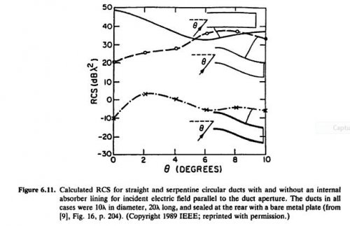
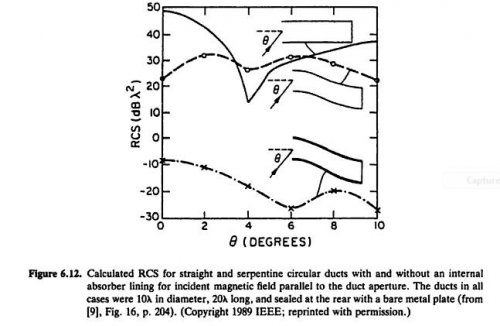
Safety; in addition, the inlet is also the three strong scattering sources for the forward direction of the aircraft. One of them accounts for 30% to 50% of the RCS (forward) of the aircraft. therefore, Countries pay great attention to the design of the inlet.
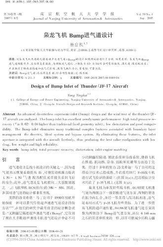
Lockheed Martin of the United States opened in early 1990 Start exploring a new alternative to traditional supersonic inlet design Methods [2-4], the most promising design concepts in their research Yes: “No Boundary Channel Supersonic Intake (Bump)”, it cancels Now most of the supersonic fighter inlets must not be designed. Less enclosing floor, venting system and bypass system, making the aircraft Ending in terms of performance, mobility, stealth, structure and quality nice. After more than a decade of hard work, Lockheed Martin’s The design technology has matured and successfully used F-16 fighters.
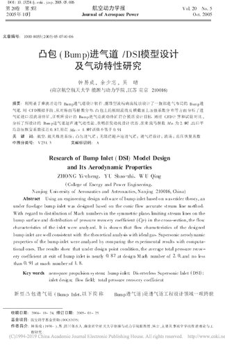
Based on the flight test verification (see Figure 1(a)), this design technique is adopted. The technique was used on the F-35 aircraft (see Figure 1(b)).
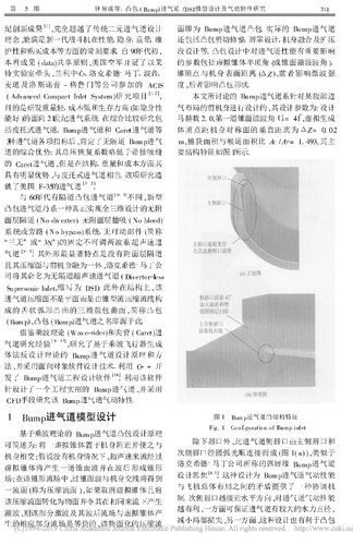
The Xiaolong aircraft is a single-engine light fighter, on 01 / 03 aircraft into the air passage is a sloping plate inlet scheme for the lower ribs on both sides, and the pipes on both sides converging in the fuselage, connected to the engine through a straight section, intake. The layout of the road is somewhat similar to that of the F-35. To further mention Supersonic performance of high aircraft, 04 / 06 aircraft inlet scheme completed on both sides of the ribbed Bump inlet scheme, station 6 146 mm
The following pipes are the same as the original to minimize structural aspects
The modification, Figure 2 is a schematic diagram of the inlet.
Figure 1 Application of Bump inlet on foreign fighters
Figure 2 Xiaolong Aircraft 04 / 06 Bump Inlet
The design of the Bump inlet scheme of the Xiaolong aircraft was carried out.
In the past two years, after 4 rounds of inlet model high-speed wind tunnel test and 1 round Low-speed wind tunnel test research, continuous improvement and improvement, and finally reached Intended purpose: Compared to the 01 / 03 conventional inlet scheme Bump inlet has higher total pressure recovery performance, in/out Good performance and stable work.
1 Bump inlet design principle
Bump inlet is based on cone flow theory [5-7], using multiplication Wave machine principle design. Convert a cone into an equivalent Compressing the surface, the resulting flow field is still a conical flow, a cone shock Attached to the edge of the compressed surface (see Figure 3). Due to the cone flow itself Characteristics, there are normal and horizontal on the compressed surface of the Bump inlet To the pressure gradient, the combined effect of the two is equivalent to the presence of a passive surface Layer blowing device that blows most of the fuselage cover layer out of the intake port. In addition, there is no boundary layer on the Bump inlet.
Good performance can also be obtained by means of blowing and blowing/puffing measures.
Figure 3 Buff inlet "passing wave" principle configuration
2 Xiaolong Aircraft Bump Inlet Design Features
The Bump inlet design points are: Maximum Mach number Ma=1. 7, pre-compression drum package equivalent compression half cone angle is 20 °, height H = 11 km and determine the capture area; in Ma = 0.8 to 1.2
Within the circumference, the throat area is determined according to the flow rate at the maximum state of the engine. The Mach number of the throat is controlled at 0. 6~0. 7; 04 aircraft inner tube The road is also different from the 01 / 03 frame, for the station 6 146 mm The front compression body, lip cover and inner pipe profile were redesigned;
After the station is 6 146 mm, it is consistent with the original, so that The structural changes are small.
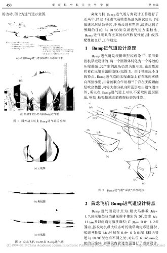
2.1 Integrated design of intake port and front fuselage
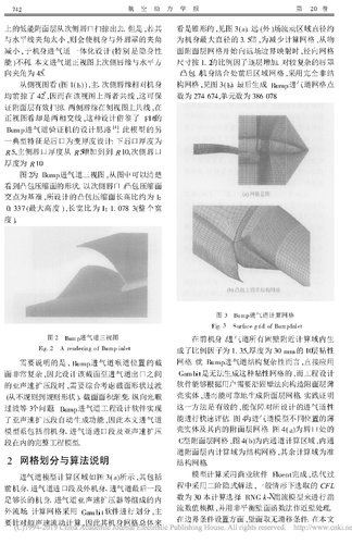
In order to reduce the resistance of the front fuselage and the thickness of the boundary layer, the front machine The body has been modified and the fuselage layer is removed. The inclined plane is changed to the curved surface (see
Figure 4), and the bulge profile is combined with the fuselage profile. Combined, the front fuselage shape is smoother.
Figure 4 Comparison of front fuselage profile changes
2. 2 lip design of the inlet
Unlike the straight lip design of the conventional air intake, Bump The lip of the airway is designed in a forward swept form with the lip adjacent to the fuselage Divided into peaks and valleys, which allows most of the boundary layer to be removed from the valley. The shape is shown in
Figure 2(c).
2. 3 further exclusion design of the surface layer on the compression drum pack
In order to better eliminate the boundary layer on the compression bulge, reduce the super Shock/surface interference at the speed of sound, compression bulge profile a method of combining a lateral pressure gradient design with a suction hole method, The suction holes are evenly distributed in the forward swept range of the lips, staggered.
2. 4 no venting door design
Because the Bump inlet uses a cone-shaped flow-passing design, the lip Three measures of mouth plucking and bulging and punching, and the surge of the intake port The degree is greatly increased, so there is no need to add a venting system.
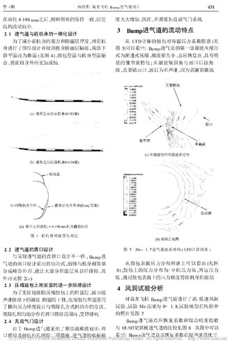
3 Bump inlet flow characteristics
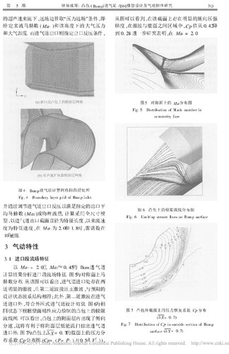
Drum symmetry plane pressure coefficient map calculated from CFD (see Figure 5) It can be seen that: the first shock compression shape of the Bump inlet The formula is progressive compression, the shock loss is small, and the total pressure is restored. Explicit cone flow characteristics; end shock angle and lip sweep angle To, and close to the lip, the wave is subsonic, should be a strong solution to the oblique shock.
Figure 5 Ma = 1. 7 inlet wave system structure (CFD calculation results)
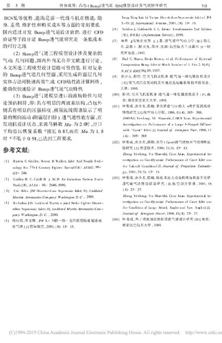
Can be seen from the surface pressure distribution map of the bulge (see
figure 6), the pressure distribution on the bulge is: high intermediate pressure, pressure on both sides Low, the fuselage boundary layer is removed by the pressure gradient on the surface of the bulge.
4 Wind tunnel test analysis
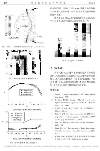
High and low speed wind tunnels were carried out on the Bump inlet of the Xiaolong aircraft Test, test Ma range 0 to 1. 8, test model in the wind tunnel The photo is shown in Figure 7.
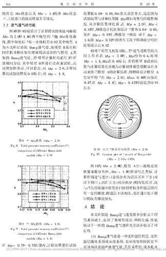
Bump inlet total pressure recovery coefficient and comprehensive distortion index
A comparison with the 01 / 03 swash plate inlet is shown in Figure 8. From the picture It can be seen that the total pressure recovery coefficient of the Bump inlet is superior to the supersonic speed section.
Figure 6 Ma = 1. 7 compression drum surface pressure distribution (CFD calculation results)
Figure 7 Bump inlet in high speed wind tunnel test
Figure 8 Inlet performance changes with flight Ma
Inclined plate inlet, e increased from 0. 02 to 0. 04, its comprehensive distortion index At the same level as the swash plate inlet, much lower than the engine distortion Limit requirements.
Figure 9 shows the Bump inlet oil flow test results, from the figure It can be seen that most of the fuselage boundary layer is discharged outside the outlet.
Figure 9 Bump inlet oil flow diagram
5 Conclusion
a
The design of the Bump inlet of the Xiaolong aircraft has reached the expected level. Purpose, the results of the wind tunnel test show: the performance of the Bump inlet Excellent, the total pressure of the inlet is restored high, compared with the swash plate inlet, e High 0. 02~ 0. 04; low comprehensive distortion index, good matching performance Well, work is stable and meets the requirements of aircraft and engines.
references:
[1 ] Seddon J. Intake aerodynamics [ R ]. AIAA Education Series, 1985.
[2] Mcfarlan J D III . Lockheed Martin’ s joint strike Fighter diverterless supersonic inlet [ M ]. National Press Club, 2000.
[3] Yang Yingkai, Li Yuxi. A JSF X-35 [J]. International aviation, 2001(8): 13-15.
[4 ] Hehs E. JSF diverterless supersonic inlet [ EB/OL ]. http: //www .codeonemagazine.com/archives/2000/Articles/july-00/divertless-1.html.
[5 ] Roe P L. Theory of waverider[C]//AGARD-LS-42, 1972: 1-17.
[6 ] Yang Yingkai. The research of bump inlet design [C] // Russian-Chinese Scientific Conference, 2003: 9-12.
[7] Liang Dewang, Li Bo. Anti-design of the air inlet without a passage and the surface layer removal machine Analysis [J]. Acta Aeronautica Sinica, 2005, 26(3): 286-289.


")