It's very helpful. Here's a translation:
Analysis on the Key Technology of Aerodynamic Design of Stealth Carrier Fighter
Fu Jiawei "*, Yu Jialong, Liu Chao, Wang Mu, and the king diligently।
1. Shenyang Aircraft Design Institute, Shenyang 1Ю035
Abstract: This article focuses on the key technical issues in the aerodynamic design of stealth carrier-based fighters, and thoroughly combs the useful engineering design experience, from the multi-objective constraints of the take-off and landing increase design, the transsonic fine drag reduction design, and the balance reduction of the whole aircraft. Three aspects, including load design, expounded the narrow-area design method of aerodynamic design under strong constraints of multiple disciplines such as performance, stability, weight, and stealth. Related analysis shows that the use of simple flaps on the trailing edge of the wing, combined with the design of three-dimensional wing surface bending and torsion and optimization of the use strategy of the rudder surface, can meet the lift requirements of carrier-based fighters under strong stealth constraints; reasonable configuration The position of the cockpit and the shock compression/expansion wave system on the upper surface of the rear fuselage, optimizing the direction of the suction vector of the intake overflow, etc., can effectively reduce the resistance of the fuselage without reducing the volume of the fuselage; use the lower surface of the fuselage The reverse bending design of the fuselage is carried out with the modification of the arresting hook door area, which can realize the load reduction of the flat tail under the severe load condition.
Keywords: stealth carrier-based fighter; aerodynamic design; narrow-area design method; increase lift and reduce drag; balanced load reduction
Chinese Library Classification Number: V241.0 Document Identification Code: A
Article number: 1000-6893 (2021) XX-XXXXXX-XX
1 Introduction
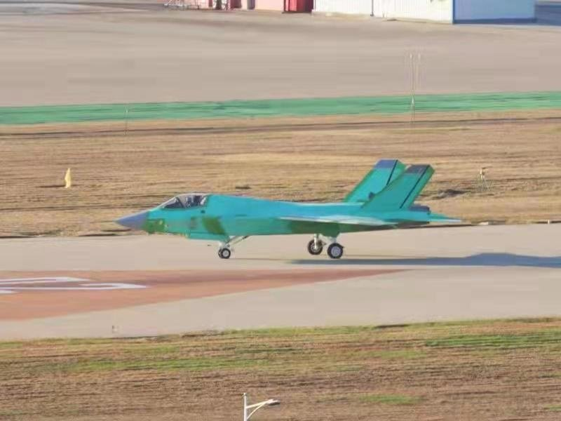
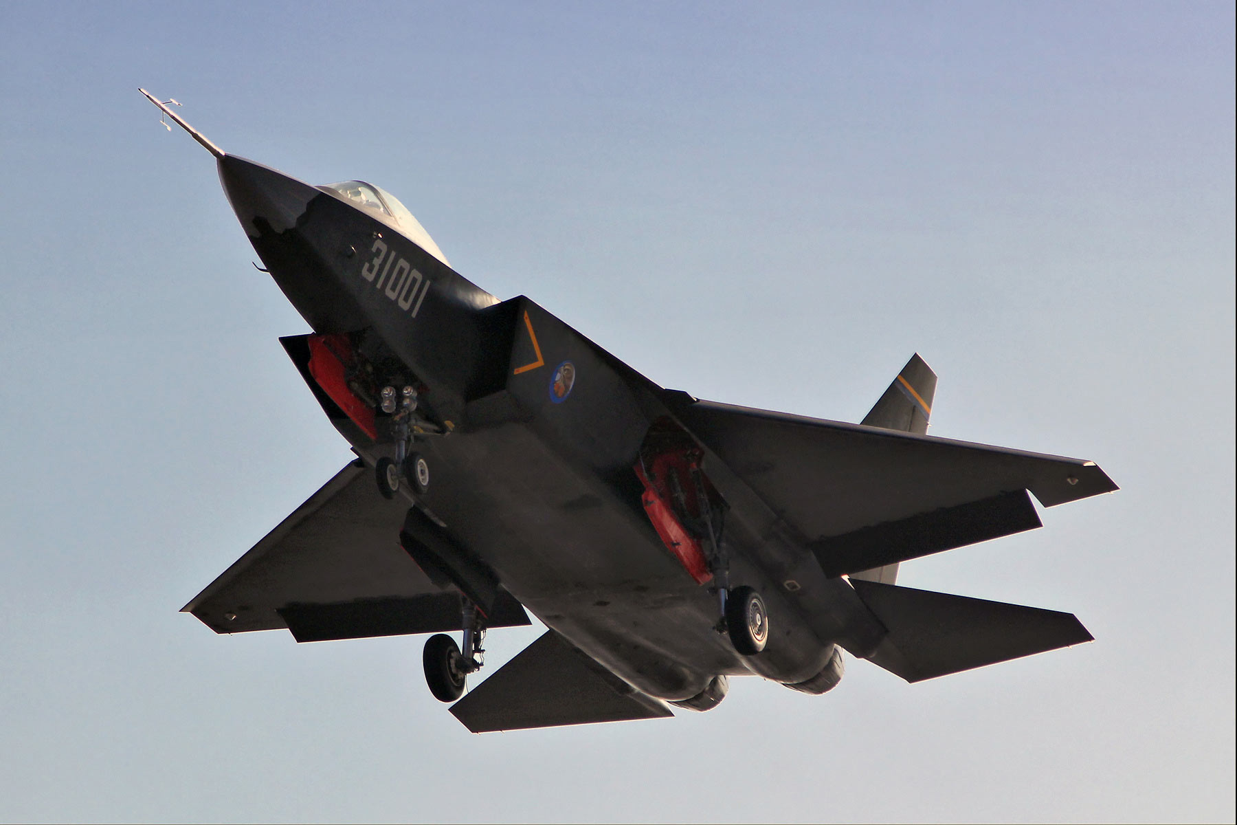
The carrier-based fighter aircraft of an aircraft carrier is an important symbol of the modern navy of a major power, and it is also the core equipment and main combat force of the aircraft carrier formation. Globally, the U.S. Navy has the most complete carrier-based fighter equipment system, and has successively developed the second and third-generation carrier-based fighters represented by F-4J, F-14, and F/A-18E/F. Up to now, it has developed to the fourth-generation stealth carrier-based fighter F-35C; the Soviet Union/Russia has developed the Su-33 and MiG 29K starting from the world’s first short take-off/vertical landing carrier-based fighter Yak-38 into service. It is the representative third-generation carrier-based fighter; in the process of developing the "Rafale" fighter, France adopted a multi-type design strategy to develop the "Rafale" M-type carrier-based fighter with three and a half generations.
The aerodynamic design and development of carrier fighter jets are accompanied by the needs of fleet air combat in different periods and the progress of aerodynamic technology worldwide. Similar to land-based fighters, the aerodynamic layout design of carrier-based fighters has evolved from the second-generation large-swept-wing aircraft layout that meets the high-altitude and high-speed combat capabilities to the third-generation side strip wing aircraft that uses the detached vortex type to enhance air mobility. Pneumatic/Stealth
The advancement of integrated design technology has developed into the fourth-generation fighter jets with high stealth performance, supersonic cruise capability, post-stall maneuverability, and embedded weapon loading capabilities. At present, the design of the aerodynamic layout of stealth carrier-based fighters not only requires a comprehensive trade-off and matching between short take-off and landing on the ship surface and high maneuverability in the air, but also requires extreme professional constraints such as stealth, performance, handling stability, and weight. Develop optimal design in a narrow design domain.
Based on the aerodynamic design of China’s current carrier fighters, this paper analyzes the difficulties faced by the aerodynamic design of next-generation carrier fighters with stealth constraints in terms of take-off and landing increase, transonic drag reduction, and balanced load reduction. Feasible solutions and summed up the useful design experience.
2 Takeoff and landing increase and lift design under multi-objective constraints
Compared with land-based fighters, the difficulty in aerodynamic design of carrier-based fighters is first to meet the requirements for short-range takeoff and landing on the ship surface, that is, the ship’s departure/landing weight, departure/landing speed, flight angle of attack and other factors. The core of the optimal takeoff and landing strategy is that the aircraft must have sufficient lift during takeoff and landing. Airplane better the lift characteristics in the take-off and landing phase, the weight of disembarkation/landing can be increased, the speed of disembarking/landing can be reduced, the angle of attack of flight can be reduced, and the performance of takeoff and landing can be comprehensively improved. The third-generation carrier-based aircraft usually uses a lifting device to provide sufficient lift increments, so that the trim lift surface of the entire aircraft meets the requirements of carrier-based aircraft on board take-off and landing, and can also take into account the air acceleration and deceleration performance of carrier-based fighters. It can be used in conjunction with other control surfaces to meet the control of the horizontal direction of the carrier aircraft during the take-off and landing process. After the carrier-based fighter introduces the constraints of stealth, it is necessary to conduct comprehensive trade-offs and optimal matching between wing design, height-increasing device, use strategy, and bending and torsion optimization.
2.1 Matching design of wings and take-off and landing
The wing is the main component of the whole aircraft to generate lift. Under the strong constraints of stealth and aerodynamic efficiency, the design range of the wing plane parameters is very small. Within a very narrow design domain, it is necessary to comprehensively optimize the leading edge sweep angle, trailing edge sweep angle, wing area, span, root tip ratio, aspect ratio and other key parameters of the wing. Based on the parameters, explore the design of high-lift three-dimensional torsion wing.
The trailing edge of the wing of carrier-based aircraft needs to be designed with maneuverable flaps, and the conventional reference airfoil cannot meet the requirements in terms of aerodynamic efficiency and structural space. The author's research shows that on the basis of the reference airfoil, the trailing edge is modified to increase the fullness of the trailing edge, and the use of a certain reverse bending design can improve the reverse pressure gradient distribution and improve the low-speed aerodynamic efficiency. Figure 1 shows a schematic diagram of the trailing edge modification of the reference airfoil.
Fig. 1 Reference airfoil and trailing edge modification
Carrier-based aircraft need to have high lift characteristics at low speeds while still maintaining good longitudinal and heading flight control capabilities (2). The high-efficiency lift device is an effective measure to take into account the characteristics of low-speed lift and high-speed maneuverability. The high-efficiency lift device can reduce the wing area to achieve the purpose of low-speed, high-lift, high-speed and high-maneuverability. Must have good takeoff and landing lift, takeoff and landing roll quality, and horizontal heading stability The requirements for performance, land-based front wheel lifting capability, low-speed and maximum head-down capability, etc. (3). At present, slotted flaps and simple flaps are mostly used in carrier-based aircraft at home and abroad. The slotted flaps are shown in Figure 2. And a schematic diagram of a simple flap. The third-generation carrier-based aircraft usually use slotted flaps. Slotted flaps have a strong ability to increase lift, but their stealth effect is poor. Stealth carrier-based aircraft are more inclined to adopt simple flap designs, which need to weigh multi-objective design constraints. The author's research on the flow characteristics and lift effect of the lifter shows that the lifter with a simple flaperon design, and the use of leading edge flaps for coordinated optimization design, can meet the demand for lift.
Fig. 2 Lifting device design
2.2 Optimization of rudder surface usage strategy
In the take-off and landing configuration, in order to optimize the lifting surface, while ensuring gentle pitching moment changes and enhancing the head-up capability during land-based take-off and landing, the design idea of the influence of the rudder surface deflection on the heading stability is considered on the basis of the design idea of the leading edge The flaps use strategy to optimize the design. Figure 4 shows the change of trim lift coefficient under different front flap skewness in the take-off and landing state. It can be seen from the figure that the use of appropriate take-off and landing configuration rudder surface strategy can greatly improve the trim lift coefficient.
Fig. 3 Distributions of trim lift coefficient at take-off and landing status.
2.3 Numerical optimization of three-dimensional surface
Design can greatly reduce the iterative design time of the aerodynamic shape. The numerical optimization algorithm is very flexible in selecting the objective function. It can be directly optimized based on a certain aerodynamic design index, such as low drag and high lift, without relying on the detailed characteristics of the aerodynamic shape. The adjoint optimization algorithm selected by the author is a gradient-based indirect optimization algorithm. The calculation time of this algorithm does not increase with the increase of design parameters, and is suitable for engineering calculations. Figure 4 shows the distribution diagram of the sensitivity distribution of the local lift of the fuselage with respect to the spatial position calculated by the adjoint optimization algorithm.
Fig. 4 Space sensitivity of the lift of the aircraft
3 Transonic speed refined drag reduction design
The requirements of stealth carrier-based fighters' blocking hooks and embedded weapons have led to an increase in the cross-sectional area of the fuselage. In order to meet the requirements of acceleration and other indicators, the layout plan faces a greater demand for drag reduction in the transonic range. In addition, due to the large wing area of carrier-based aircraft, and the design of the wing is restricted by structural height and fuel tank volume, the design space for drag reduction through wing-shaped bending and torsion configuration is small. The surface of the fuselage is subject to the overall layout, The height of the structure, the field of vision of the pilot, the design of the platoon system, the stealth geometry and other factors are strongly constrained, and the adjustment margin of the overall shape of the aircraft is also very limited.
Based on the above-mentioned drag reduction requirements and the many difficulties faced, the author has proposed a transonic fine drag reduction design method based on comprehensive consideration of the overall, stealth, structure, and propulsion system professional design requirements. Through refined numerical simulation calculations, the aircraft surface pressure distribution and spatial flow field characteristics are obtained. On this basis, the relationship between the local surface pressure and the spatial flow field such as shock wave/expansion wave/overflow is deeply analyzed, and then the reduction is proposed. Shock wave compression angle, reduction of expansion wave intensity, reasonable matching of compression/expansion wave system, optimization of overflow suction vector direction and other systematic drag reduction measures. Through optimization and adjustment of local contour surfaces, the airframe is refined and designed for drag reduction. Corresponding wind tunnel tests show that through the above-mentioned drag reduction measures, the whole machine can obtain about 10% of drag reduction benefits, which meets the horizontal acceleration index. Figure 5 shows the drag reduction gain with Mach number
Fig. 5 The benefits of supersonic drag reduction
3.1 Optimization of cockpit position shock compression/expansion wave system
The main contribution of transsonic resistance is the wave resistance generated by the shock wave. The larger the forward windward area and the greater the shock wave compression angle, the greater the local wave resistance generated. Through the flow field analysis of the whole aircraft, it is found that the shock wave intensity at the front fuselage and cockpit is the largest, which has a significant impact on the transonic resistance of the whole aircraft. Since the configuration of the front fuselage is subject to overall and stealth constraints, the adjustment of the front fuselage shape focuses on optimizing the profile of the front nose. On the basis of ensuring the same viewing angle, uniform transition between the upper surface of the front nose and the profile of the windshield transition zone can reduce the shock compression angle at the front fuselage and cockpit, and reduce the local shock intensity. Figure 6 shows the design diagram of the shock wave compression angle at the cockpit. The corresponding numerical simulation results show that reducing the shock wave compression angle at the front fuselage and the cockpit can reduce the local shock wave intensity to a certain extent. In turn, the transonic resistance is reduced.
Fig. 6 Design drawing of the compression angle at the cockpit
During the cruising of the fighter jet, a strong shock wave will be generated at the cockpit and other forward windward parts. After the shock wave, the pressure will gradually recover through the expansion wave, and back pressure will appear behind the shock wave. Gradient area, resulting in increased resistance of the whole machine. Numerical simulation analysis of the local flow field shows that the expansion wave behind the cockpit at the front fuselage has a greater intensity and has a greater impact on the resistance. Properly heightening the cockpit ridge surface can reduce the surface airflow expansion intensity and achieve the optimization of the reverse pressure gradient. Figure 7 shows a comparison diagram of the optimized configuration of the cockpit before and after. The red represents the original scheme, and the green represents the optimized scheme. Figure 8 shows a comparison diagram of the numerical simulation before and after the ridge optimization. It can be seen from the figure that after the optimization, the strength of the expansion wave after the front fuselage cockpit is reduced, which in turn leads to a decrease in the transonic resistance.
Fig. 7 Comparison of the configurations of cockpit before and after optimization
Fig. 8 Comparison of the contours of pressure coefficient at ridge lines
3.2 Optimization of the suction vector direction of the inlet overflow
Due to the overflow effect of the intake duct, the expansion airflow passing through the edge of the lip will produce a suction peak perpendicular to the local profile. Through the analysis of the local flow field, it is found that when the transonic velocity is zero angle of attack, the overflow at the upper lip is more obvious, which in turn produces a strong suction expansion zone. The lip is relatively flat in the shape of traditional fighter jets, and the contribution of the main suction peak is mainly concentrated in the direction of lift. Based on this feature, the profile above the lip can be optimized, and the leading edge suction can be adjusted to the opposite direction of the resistance, so as to achieve the purpose of using overflow suction to reduce drag.
Figure 9 shows a comparison of the configuration before and after the optimization of the inlet lip. Red represents the original scheme, and cyan represents the optimized scheme. Figure 10 shows the comparison diagram of the front and rear lip suction. The suction in the original lift direction becomes smaller, and the direction is changed to the opposite direction of the resistance.
Fig. 9 Comparison of configuration of inlet lips before and after optimization
Fig. 10 Comparison of lip suction before and after optimization
3.3 Optimization of shock compression/expansion wave system of rear fuselage
Since the rear fuselage has a flat tail, a vertical tail, and other tail surfaces, as well as a curved surface that is suitable for the installation of the engine, its contribution to the resistance is more significant. Using refined simulation methods to analyze the local flow field of the coupled flow of multiple components such as the vertical tail, engine compartment, nozzle, and flat tail, it is found that at the leading edge of the vertical tail root, the upper surface of the rear fuselage is locally heightened, and the vertical tail can be used. The shock wave generates high pressure on the leeward surface of the convex curved surface of the engine compartment, thereby producing a drag reduction effect. Figure 11 shows the configuration comparison of the rear body and the nozzle before and after optimization. Red represents the original plan, and green represents the optimized plan.
Fig.11 Comparison of the configuration of afterbody before and after optimization
In order to meet the requirements of blocking the ship and folding the wings, the carrier-based aircraft will pay a heavier weight price. In order to ensure the effectiveness of air combat, the weight of the air plane needs to be strictly controlled. The flight load is the link between combat use and the load on the airframe, which is very important for the weight reduction design of the aircraft."
In the load shedding design process of the stealth carrier-based fighter, it is necessary to apply the full envelope flight load balance design technology to carry out the load shedding design. This requires comprehensive consideration of overall, aerodynamics, performance, stability, flight control, strength and other professional aspects. Design constraints, comprehensively evaluate sub-, trans-, and supersonic maneuvering flight requirements and maneuvering flight conditions to study the load reduction design process, and then form a flight load balance design plan for the entire aircraft, establish accurate and reasonable load calculation and analysis models, and solve the problem of load reduction design and combat use The design contradiction between the two, the realization of the flight load reduction design of the whole aircraft, and the effect of supporting the aircraft to achieve the weight target.
4.1 Flat tail trim load balance design
Aiming at the problem of excessive negative load on the flat tail in the design of carrier-based fighter jets, a joint iterative design of layout and load was carried out. Taking into account the symmetrical characteristics of flat tail carrying capacity, the flat tail positive load was balanced to achieve load reduction. Figure 16 shows the flow chart of the iterative design of layout and load. With the flat tail unloading as the target direction, the fuselage reverse bending design can be realized by using the surface modification of the lower surface of the fuselage to realize the flat tail unloading under severe load conditions. Figure 17 shows a schematic diagram of the rear fuselage reverse bending design.
Fig.16 Schematic of joint iteration design of layout and payload
Fig. 17 Schematic of the negative bowed afterbody
Studies have shown that every time the longitudinal moment coefficient increases by 0.005, the transonic trim resistance can be reduced by about 5%, which in turn reduces the balance load of the flat tail by about 5%.
4.2 Load balance design of the whole machine
When a carrier fighter is flying in vertical and horizontal directions under the condition of tightly coupled wing/flat tail, there is a strong interference relationship between the flaperon and the flat tail. (2) On the basis of ensuring the aerodynamic efficiency and the achievable twisting moment, for the same overload With the rolling angular velocity index, the optimal load ratio range is sought through the load balance design of the whole machine, so as to realize the comprehensive load reduction of the whole machine.
Figure 18 shows the effect of different control surface combinations on the wing/flat tail surface load. Numerical simulation calculations show that the optimal load balance design of the entire aircraft has obvious benefits. On this basis, the optimal load ratio interval design has been further carried out to realize the comprehensive load reduction of the wings and the tail.
Fig. 18 Distributions of payloads on wing under the condition of rolling and negative overloads.
5 Conclusion
Through the mechanism research and simulation analysis of the key technical issues in the aerodynamic design of the stealth carrier-based fighter, the following main conclusions are obtained:
1) The design of simple flaps on the trailing edge of the wing, combined with the numerical optimization of the wing profile surface bending and twisting and the matching of the rudder surface use strategy, can meet the lift requirements of carrier-based fighters under strong stealth constraints;
2) Reasonable configuration of the cockpit position and the shock compression/expansion wave system on the upper surface of the
rear fuselage, optimizing the direction of the suction vector of the intake overflow, etc., can achieve about 10% of the entire aircraft without reducing the volume of the fuselage. Drag reduction gains;
3) Utilize the modification of the lower surface of the fuselage and the door area of the arresting hook to carry out the reverse bending design of the fuselage, which can realize the negative load of the flat tail.