Flying Flapjacks

*Nods*

Thank you for taking the time to answer my query.

No, not the 'counter-rotating to counter tip vortex' thing.

But some sort of articulation 'flappy-ness' in the actual blades themselves.

I seem to recall it was one of the things that caused the machines production to fall behind. With the company not seeming to thknk it was needed, then much testing and errors coming about and the system thence bwing 'put back the way the designer intended'.

I also apologize if my sever lack of any technical knowledge is a hindrance. *Bows*

Much cheers to you and yours.
 
Oh, sorry for misunderstanding ;)
The flapping of the blades might have been necessary because at high angles of attack the props are operating in a strong edgewise flow (not unlike a helicopter rotor). The advancing and retreating blades see differing inflow velocity and need to flap to balance thrust across the disc.
Maybe someone else has a better explanation?
 
AeroFranz said:
Oh, sorry for misunderstanding ;)
The flapping of the blades might have been necessary because at high angles of attack the props are operating in a strong edgewise flow (not unlike a helicopter rotor). The advancing and retreating blades see differing inflow velocity and need to flap to balance thrust across the disc.
Maybe someone else has a better explanation?

That's basically it. If the propeller on the flapjacks didn't flap, there would be excessively high loads at the attachment of the blade to the hub as the lift on it increased and decreased as the blade advanced and retreated relative to the inflow. While these loads are present on all propellers when operated at high angles of attack, they are much higher on the V-173 and F5U because of the higher angles of attack they were capable of and the length of the blades.
 
I read somewhere, I don't recall where, a modern technical assessment of the XF5U. The verdict was that, because of the flapping airscrews, Vought had unwittingly ventured into the helicopter vibratory realm and that, had it flown, this would have ground the program to a halt. I can't defend this theory, but it seems plausible in the absence of any evidence. The pancake was unlike anything else flying at the time and might well have been shook in ways that were beyond the structural engineering knowledge of the day.
 
Ah! *Nods*

Cool!

Thank you all very much for your time and responses. :)

Much cheers to you and yours.
 
A shot of the restored V-173 taken in February.
 

Attachments

  • DSC_0076 ES2s.JPG
    DSC_0076 ES2s.JPG
    277.5 KB · Views: 853

Attachments

  • Alfa V-173 01.jpg
    Alfa V-173 01.jpg
    51.2 KB · Views: 775
  • Alfa V-173 02.jpg
    Alfa V-173 02.jpg
    85.5 KB · Views: 728
  • Alfa V-173 03.jpg
    Alfa V-173 03.jpg
    11.2 KB · Views: 714
  • Alfa V-173 04.jpg
    Alfa V-173 04.jpg
    18.7 KB · Views: 729
taildragger said:
I read somewhere, I don't recall where, a modern technical assessment of the XF5U.

Did you mean this PDF:

http://www.eaach1.org/Design/DGIIcom3.pdf
 
No, I haven't seen that before, but the article makes it clear that vibration was a major problem encountered during ground testing. The account I remember was more of an engineering analysis and speculated that the program would have run into vibration problems that were beyond the current state of knowledge had it progressed to flight testing. It sounds like Vought actually got a pretty good taste of these and that they may have been a major reason for the project's termination.
 
There's a rather good article about the V-173 and XF5U-1, in the November and December 1975 issues of 'Aeroplane Monthly', written by Art Schoeni.
I wont post the whole article, obviously, but here are some pertinent quotes and images :-


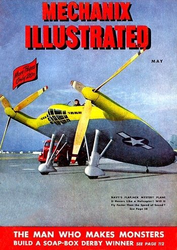
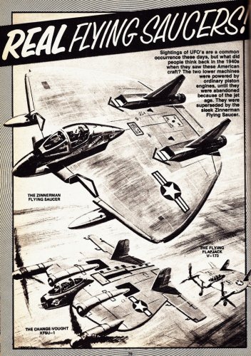
"In a design competition at NACA in 1933
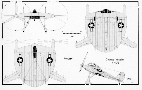
he [Zimmerman] designed a circular-wing aeroplane
that was to fly at high speed and yet
hover like a helicopter.
His design won the competition with its
aerodynamic excellence and sound engineering.
However, NACA rejected the idea for further
development because it was "too advanced".


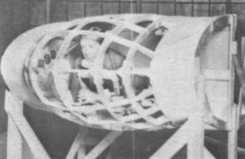
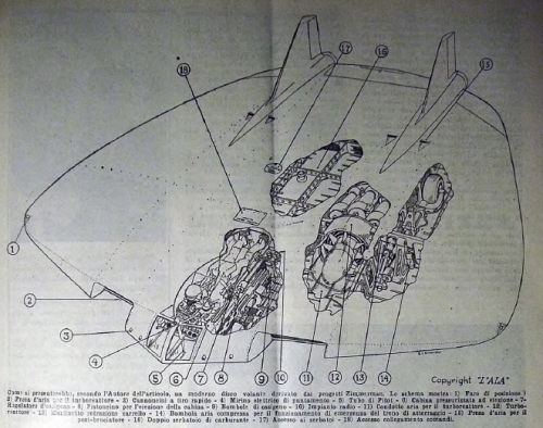
As originally planned, the little aircraft was to
carry three passengers lying prone to promote
streamlining, changing to upright position in flight.
The idea was incorporated in a US patent
procured by Zimmerman in 1938,
but he had abandoned it before
then as being marginal in comfort.

The design called for the ultimate
lighter to have large props with
helicopter-like flapping blades that
would support it in hovering flight.
Thus there was talk of an
aeroplane that could take off vertically
and fly forward at 500 m.p.h.

Before Guyton made the V-l75’s
first flight, full-scale wind tunnel tests
at Langley Field indicated that the
high induced drag of the low aspect
ratio wing would be partially com-
pensated for by the interaction of the
large props rotating in opposite direc-
tions ahead of the wing. Wing tip
vortices which cause loss of lift on
conventional wings were nullified by
having each propeller rotating counter
to the vortices.

vibration in the cockpit was a per-
sistent problem. This was caused by
resonant frequency between the pro·
pellers and the nacelle structure,
which Zimmerman greatly alleviated
by installing vibration dampers on
the propellers. The problem was not
met in the heavily constructed XF5U-1,
but it led to development of articu-
lated propeller blades in the fighter
to avoid the non-symmetrical airflow
at high angles of attack.

"Being a former naval carrier pilot,
I was keen for the idea of vertically
landing a 500 m.p.h. fighter to a hook
installation on a cruiser or battleship."
[Boone T. Guyton, V-173 test pilot.]

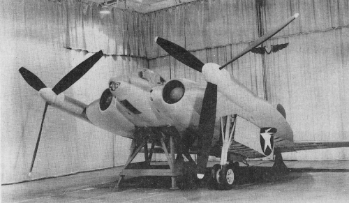
Full-scale wind tunnel tests of the
Pancake were run in September 1941,
at NACA’s Langley Field, Virginia.
Following successful completion of
these, the Navy asked Vought to
design and build two military versions
of the VS-515, which were designated
the XF5U-1. One would be a flight test
aircraft and the other for static testing
in the laboratories.

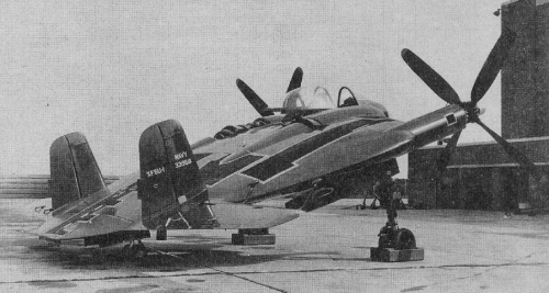
completed June 7. 1943. By November
it was decided that the interim propellers
on the XFSU-1 would not do,
and that propellers with articulated
or "flapping" blades would be
required.

Gear box problems in the big right-
angle. drive shafts to each propeller
had negated the chance to fly the
XF5U-1 safely from any airfield other
than Muroc. The quarter-million dollar
price tag on a test programme also
was a factor—the Navy preferred to
spend the money on jet aircraft. The
complicated shafting and gear boxes
developed by Vought engineers
presented problems that might. have
hampered the project anyway. Other
turboprop projects of that era also
were having gearbox trouble.

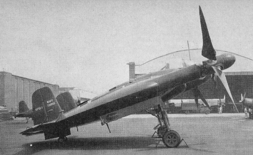
The original propellers installed on
the XF5U-1 lighter were conventional
Hamilton Standard Hydromatics,
similar to those on the F4U-4 Corsair.
When it was discovered that flapping
blades would be required to avoid
vibrration by unsymrnetrical airflow
and to resist heavy loads when flying
at high angles of attack, Zimmerman
had a problem.
The new props were de-signed by
Zimmerman with Vought engineers’
help and built by Vought. "For a time
it appeared the project would have
to be abandoned," Zimmerman said,
"but after a desperate weekend of
work I came up with a design using
two pairs of teetering blades, similar
to the Bell helicopter rotor, one pair
mounted ahead of the other to form
a four-bladed propeller"

Vought's machine was expected to
achieve a speed range from 40 to 425 m.p.h
with the original engines, 20 to 460
m.p.h. with water injection engines,
and 0-550 m.p.h. with gas turbine
powerplants.

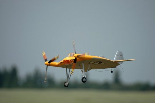
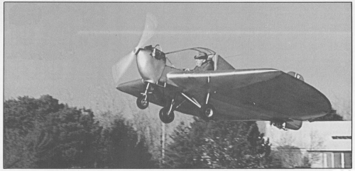
Guyton and William Millar, another
company test pilot later killed in an
F7U-1 Cutlass crash, made numerous
taxi tests in the XF5U-1. On one
occasion it lifted briefly off the runway,
a common occurrence on early
test runs."


In the PDF posted by mboeller, above, it's stated that the XF5U-1 was scrapped at Edwards, whereas Schoeni says that the XF5U-1 never went to Muroc, as it then was, instead being scrapped at the Vought plant.
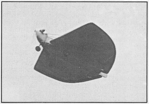
Likewise the PDF says that the V-173 originally flew with a prone pilot arrangement, however Schoeni makes no mention of this, and I've not seen any images of the V-173 with a prone cockpit, other than the one from the 'Aeroplanes Vought' book, (available online at http://celticowboy.com/AV2/index.htm) posted below.


cheers,
Robin.
 

Attachments

  • xf5u-1.png
    xf5u-1.png
    112.1 KB · Views: 241
  • xf5u-1 with flapping blades.png
    xf5u-1 with flapping blades.png
    409.2 KB · Views: 156
  • xf5u-1 with four blade hydromatics.png
    xf5u-1 with four blade hydromatics.png
    365.8 KB · Views: 163
  • xf5u-1 mockup with three bladers.png
    xf5u-1 mockup with three bladers.png
    419 KB · Views: 175
  • vought V-173 prone pilot mock-up.png
    vought V-173 prone pilot mock-up.png
    292.7 KB · Views: 194
  • v-173.png
    v-173.png
    162.9 KB · Views: 219
Robunos,


thanks for taking the time to post parts of the article. I have been trying to figure out if there is actually truth to the widely reported statements of reduced induced drag thanks to counter-rotation of the props. In the book "Radical wind tunnels" the assertion is made that wind tunnel tests showed little or no difference with models having either sense of rotation. I need to find the relevant NACA paper on NTRS...
 
AeroFranz said:
Robunos,


thanks for taking the time to post parts of the article. I have been trying to figure out if there is actually truth to the widely reported statements of reduced induced drag thanks to counter-rotation of the props. In the book "Radical wind tunnels" the assertion is made that wind tunnel tests showed little or no difference with models having either sense of rotation. I need to find the relevant NACA paper on NTRS...

It would seem considering the the size of the propellers to the wing, they would dominate the flowfield, regardless of rotation. I think I would be more concerned with their effect on alpha, more so than induced drag.

However, they may have reduced induced drag at higher alpha simply be energizing the airflow at higher angles of attack. Or to put it another way, at higher angles of attack, propulsive lift relieves the wing of having to lift as much, thereby reducing induced drag.

Which gets into what I would like to know. Did the propellers flow field effectively make the lift curve of the wing itself flatter but at a higher coefficent of lift than an equivalent planform without being in a propellers flow field? let me know if you run across any lift curve slopes for the models in powered flight. I would also like to know how it was effected based on power/prop pitch settings.
 
This any help?...


"LANGLEY FULL-SCALE TUNNEL INVESTIGATION OF A 1/3-SCALE MODEL OF THE CHANCE VOUGHT XF5U -1 AIRPLANE"


http://ntrs.nasa.gov/archive/nasa/casi.ntrs.nasa.gov/20050019375_2005009856.pdf


"The results of investigation of a 1/3-scale model of the
Chance Vought XF5U-l airplane in the Langley full-scale tunnel are
presented in this report. The maximum lift and stalling characteristics
of several model configurations, the longitudinal stability
characteristics of the model, and the effectiveness of the control
surfaces were determined with the propellers removed. The propulsive
characteristics, the effect of propeller operation on the
lift, and the static thrust of the model propellers were determined
at several propeller-blade angles."


"The peak propulsive efficiencies for f3 = 200 and f3 = 300
were increased 7 percent at CL 0.67 and 20 percent at CL 0.74,
respectively, with the propellers rotating upward in the center than
with the propellers rotating downward in the center."


cheers,
Robin.
 
I have to say, it's my opinion that any reduction in induced drag/increase in propulsive efficiency was only a bonus of this configuration, and that the main reason for it's use was to allow the use of large diameter proprotor type propellers, to enable hovering and thereby VTOL...


cheers,
Robin.
 
While looking for something else, as always, I found another 'flying flapjack', the Hatfield 'Little Bird', and the story behind it, is well....
In 1926, at the age of 18, Milton Hatfield built his own aeroplane, from Nicholas Beazly plans. (Does anyone know what this 'plane would have looked like?) He also converted the engine from a ex-police motorcycle engine. He also bought a set of wheels and tyres. The aircraft never flew. Hatfield's father insisted that the young Hatfield get a pilot's licence first. However, since an hour's flying lesson cost two week's wages, Milt still had not soloed by 1932. He had also married in 1931.

Then Milt caught a break. Cloyd Snyder, the inventor of the yet-to-be named Arup, wished to convert his 'Snyder Glider', into a powered aircraft, eventually the Arup no.1. To do this he needed an engine, and some wheels. Young Milt had just what he needed. A deal was struck, Milt would let Snyder have his aeroplane, and Glen Doolittle, Snyder's test pilot, would teach Hatfield to fly. After two hours tuition, Milt soloed and obtained his licence.
By 1935, Hatfield was working in aviation, skywriting. The Arup organisation, in contrast was on it's knees. They sold the engineless Arup No.2 to a stunt flyer named Franks, who installed the same type of engine, a 3-cylinder Szekeley, as in Milt's plane. However, neither Franks, nor several other pilots was able to get the Arup into the air. In the end, the propeller was broken. Of course Franks asked Hatfield for the loan of HIS propeller. Milt agreed, but on condition that he flew the Arup. (He had watched the others' attempts, and worked out where they had gone wrong) With his propeller fitted. Milt climbed in, and flew the Arup without problems. Then he told Franks 'how to do it'. Soon after, Milt was also flying the Arup No.4 as well. He never forgot his time flying these aircraft.
After a long and varied career in aviation, and other industries, Milt Hatfield retired. He started building aeroplanes again. In 1985 he decided to build a microlight version of the Arup concept. Built of steel tube and wood, and powered by a 27 hp Rotax engine, the first version had 'Junkers-style' separate elevons, along with spoilers. The wing was arranged to fold up against the fuselage, to allow the 'plane to be towed behind a car. The structure was fabric covered, the engine cowling glass fibre. and the canopy was heat-shrunk Mylar. Milt named his aircraft 'Little Bird'.
Following fast taxiing tests, it became clear that the original elevons were ineffective. These were removed, and the trailing edge of the wings aft of the rear spar cut away, and hinged to act as elevons. The spoilers were deleted. On May 27th, 1987, the aircraft flew for the first time. Flight characteristics were good, two quirks of the configuration being the abilty to turn using rudder or the stick only-no need to use both- and a stable rapid sink rate at low speeds and high angle of attack.
From 'Aeroplane Monthly', September 1987.


cheers,
Robin.
 

Attachments

  • little bird 3-view.png
    little bird 3-view.png
    83.8 KB · Views: 194
  • little bird #5.png
    little bird #5.png
    369 KB · Views: 918
  • little bird #4.png
    little bird #4.png
    523.4 KB · Views: 959
  • little bird #3.png
    little bird #3.png
    340.2 KB · Views: 1,012
  • little bird #2.png
    little bird #2.png
    442.2 KB · Views: 1,087
  • little bird #1.png
    little bird #1.png
    297.3 KB · Views: 1,172
Doing a bit more digging, it seems that Milt Hatfield built 3 Little Birds in total, each one differing from the others. #2 and #3 incorporated fibreglass in their construction, to varying degrees. All three still survive, but not in flyable condition.
See here :-
http://www.oshkosh365.org/ok365_DiscussionBoardTopic.aspx?id=1235&boardid=147&forumid=180&topicid=4813
and here :-
http://www.homebuiltairplanes.com/forums/members/littlebird-albums-little-birds.html


cheers,
Robin.
 
Re: Italian all-wing aircraft

fluxflyer said:
A former U.S. Air Force test pilot, Chuck Tucker had recently tested a low aspect flying wing
model he designed named Vortex. It was a scaled down prototype of 12 ft. span and 10 ft. chord
rectangle. The tricycle landing gear had mains, wingtip mounted, and nose, beneath firewall ,
squared off wingtips and a large center mounted vertical stabilizer, rudder. Chuck's Vortex
project may have been adopted and ompleted by model club members of Morgan Hill, California
after He passed away more than a year ago. There were a few photos of Vortex posted at

http://twitt.org , month unknown.
See pages 6, 12, 15 and 16 of the pdf document in the link:
http://www.sccmas.org/wp-content/uploads/2013/11/2007_November.pdf
 
Re: Italian all-wing aircraft

pesholito said:
fluxflyer said:
A former U.S. Air Force test pilot, Chuck Tucker had recently tested a low aspect flying wing
model he designed named Vortex. It was a scaled down prototype of 12 ft. span and 10 ft. chord
rectangle. The tricycle landing gear had mains, wingtip mounted, and nose, beneath firewall ,
squared off wingtips and a large center mounted vertical stabilizer, rudder. Chuck's Vortex
project may have been adopted and ompleted by model club members of Morgan Hill, California
after He passed away more than a year ago. There were a few photos of Vortex posted at

http://twitt.org , month unknown.
See pages 6, 12, 15 and 16 of the pdf document in the link:
http://www.sccmas.org/wp-content/uploads/2013/11/2007_November.pdf


More pictures of the same airplane:


Re: Italian all-wing aircraft

That's a Models,great find Pesholito.
 
cluttonfred said:
I am sure everyone is familiar with the 1940s V-173 and XF5U-1 projects. If not, the Vought Heritage Museum has some nice pages and pics here: http://www.voughtaircraft.com/heritage/products/html/v-173.html

I know of the similar Boeing design from the same era, the Model 390/391. Aerofiles.com has a little info and a pic on that one here (scroll down to the 390): http://aerofiles.com/_boe.html

I know of some pre-war and WWII-era design like those, but does anyone know of any similar low aspect ratio designs in the post-WWII era?

And no, I don't mean something like the Lockheed F-104, which certainly has low aspect ratio wings. I mean low-aspect ratio flying wings or something otherwise similar to the Vought and Boeing designs above.

Thanks and regards,

Matthew
I am looking for more information on the Boeing 390, 391, 396 projects. Does anyone have any more, not posted here?
 
Hi Pesholito,please see;


http://aerofiles.com/_boe.html
 
Re: Italian all-wing aircraft

Flying toast, to go with our flying flapjacks...(just need eggs and bacon, now... ;D B) )

cheers,
Robin.
 
Brief write-up on the XF5U.
http://www.jitterbuzz.com/MAN_1947_01.HTML


And here's a PDF of Modern Mechanix's May '47 piece on Vought's Flying Pancake projects. Love the cutaway graphics! You gotta love these old-school scientific articles! Especially when you can appreciate that no computers were used for the illustrations back then. Those cutaway graphics were done by hand. No CG.
http://www.jitterbuzz.com/manreal/flying_flapjack_mechanix_05_1947.pdf
 

Attachments

  • MAN_Jan_1947.jpg
    MAN_Jan_1947.jpg
    318.5 KB · Views: 177
  • MechanixIllustrated1947.jpg
    MechanixIllustrated1947.jpg
    87.3 KB · Views: 156
Hi,

here is a flying flapjack concept,created by Mr. Charles Zimmerman,maybe it
was a real design.

http://www.avia-it.com/act/biblioteca/periodici/PDF%20Riviste/Ala/L'Ala%201950%2004.pdf
 

Attachments

  • 1.png
    1.png
    266.9 KB · Views: 1,155
  • 2.png
    2.png
    701.5 KB · Views: 1,255
  • 3.png
    3.png
    558.8 KB · Views: 1,066
While the Cylons would have loved this one, it is not an actual design according to the caption, but rather the author's conception of a "modern flying saucer derived from the Zimmerman projects." Oddly, the author's name is Sergei Sikorsky.
 
hesham said:
here is a flying flapjack concept,created by Mr. Charles Zimmerman,maybe it
was a real design.

http://www.avia-it.com/act/biblioteca/periodici/PDF%20Riviste/Ala/L'Ala%201950%2004.pdf

Looks like this concept;

http://www.secretprojects.co.uk/forum/index.php/topic,2925.210.html
 

Attachments

  • Real Flying Saucers.jpg
    Real Flying Saucers.jpg
    535.2 KB · Views: 1,034
Actually, the props de-stabilize rather than stabilize the aircraft. If it were a pusher, then the props would stabilize.
 
But you do lose the theoretical benefits of having the propwash pushing over the lift/control surfaces, I should think.
 
Regarding the Boeing 390: Does anyone have dimensions or specifications (e.g. weights)?

I've found a couple low-quality scans of drawings showing the internal structure but I can't make out any information regarding the scale of the design.

*edit - largely solved due to the help of an intrepid forum member*
 
_Del_ said:
But you do lose the theoretical benefits of having the propwash pushing over the lift/control surfaces, I should think.

The key invention of Zimmermann's 'Flying Pancake' design is that the propwash reduces drag. At low velocities it does enable the wing to generate lift and it provides control authority but the location and rotation of the propellers is all about drag. Low aspect ratio wings with high chords towards the tip (ie square or round wings but not deltas) have large wing tip vortices. These vortices generate induced drag and getting rid of them is what winglets do on your typical airliner. On the Flyjng Pancake the propellers are located along an axis very close to the wing tip and counter rotate against the wingtip vortices. So the propwash of the air screws cancels out the vortices and therefore improves the lift drag ratio if the wing. So you get the high lift at low velocity benefit of the very low aspect ratio wing without the high induced drag of the same wing especially at higher velocities.

So everytime you see a Flyjng Pancake design without the wing tip props you can bet it wasn't designed by an engineer and though it would fly it would be very slow like any other typical LR wing STOL aircraft (PC-6 Porter, Scottish Pioneer, DHC Caribou, etc). Perhaps you could make a jet powered Flying Pancake but you would need engine bleed air blowers along the tips. And the power of the blowers would have to increase as your airspeed increased to counter increasing induced drag.
 
"Low aspect ratio wings with high chords towards the tip (ie square or round wings but not deltas) have large wing tip vortices that spill out and down from the top tip of the wing."

Actually, the air under the wing wants to go up. If you look at the left wingtip from behind, the vortice is rotating clockwise, up and in. The left propeller is rotating counterclockwise when viewed from the rear to counteract this.
 
Lol yes. I tried to write that message three times in the midst of doing something else and for some reason got downwash in the brain making me think the vortices go down... But really I should have been trying to think less and just remember all those great sights of planes landing where you can see the vortices spining up and over behind the wing tips. I think there was a great scene in Top Gun with that...
 
Back
Top Bottom