blackkite
Don't laugh, don't cry, don't even curse, but.....
- Joined
- 31 May 2007
- Messages
- 8,286
- Reaction score
- 5,840
Hi!
 nhungdoicanh.blogspot.com
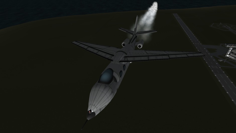
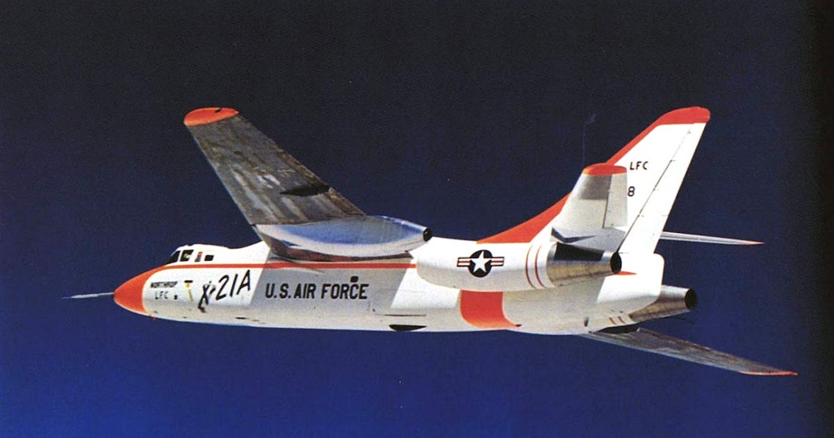
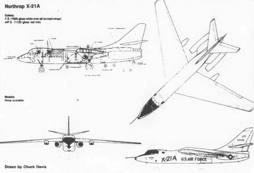
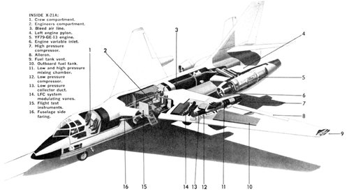
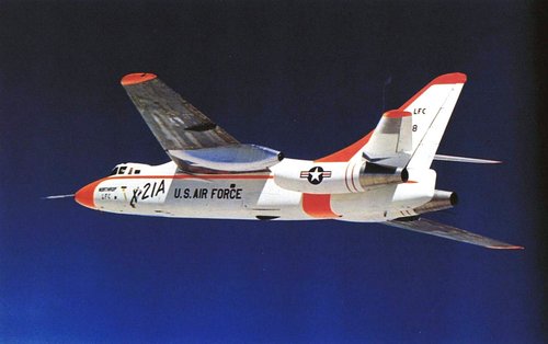
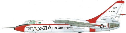
Northrop X-21
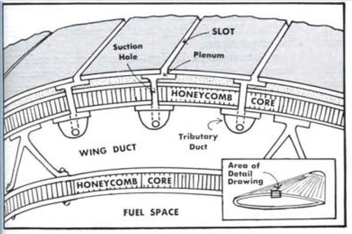
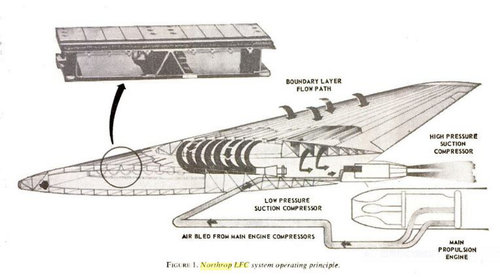
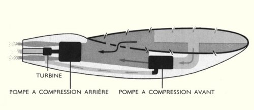
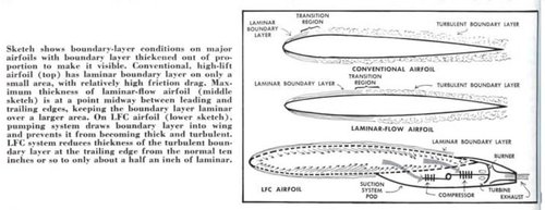
X-21 PHI CÆ NGHIÃN CỨU "KIá»M SOÃT DÃNG CHẢY Bá» MẶT CỦA CÃNH" (LAMINAR FLOW CONTROL) Northrop Corp. (Mỹ) _______________________________...
nhungdoicanh.blogspot.com
Attachments


Last edited: