Hi!
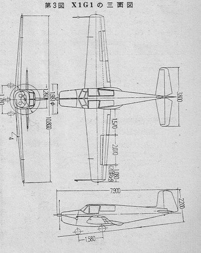
1.X1G1 form
The test period for the first form, X1G1, is from December 1957 to August 1958 and has three features.
• Full span flap
The flap, which is the easiest device to increase the lift, has a larger flap area, so the entire width of the trailing edge of the main wing is divided into three large flaps.
• Double gap flap
Insert a long small wing spanning about 80% of the wing width between the flap and the main wing to provide a gap, and supply air flowing under the wing to delay the separation of airflow on the top of the flap and stall Slowed down
• Spoiler
A spoiler is a device that controls the roll axis as an alternative to ailerons because it is not possible to place ailerons (blades) when full span flaps are used.
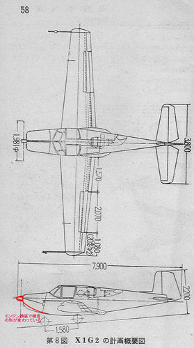
2.X1G2 form
The X1G2 form was tested from April 1959 to the end of 1960. When the flight speed is reduced and the angle of attack of the wing is increased by the blowout wing (Boundary Layer Control Technology BLC), which is a modified main wing, strong air with a compressor etc. Research was conducted to replenish airflow and prevent separation. Equipped with a gas turbine engine as high-pressure airflow for the blowing wings, a fuel tank was relocated inside the main wings. In addition, as a countermeasure against the increase in weight, the engine has been powered up, and as a result, 2.3 times the lift of the normal form has been demonstrated.
3.X1G3 form
The X1G3 form was tested between 1962 and August 1963. It features a newly manufactured main wing equipped with a wing end plate with a retractable slit. The tendency of the lateral control (roll) generated by low-speed flight of short-range take-off and landing aircraft to become dull was one of the issues for practical application. Toward this improvement, research was conducted to attach wing tip plates at both ends of the wing to suppress the wing tip vortex (induced vortex) generated at the wing tip to increase lift, and to provide an openable slit on the wing tip plate. This is the form.
However, although it was confirmed that the wing tip plate was effective enough for lateral control, there was another problem that air resistance increased and take-off and landing in a cross wind became difficult, and it was not applied to practical aircraft.


 elpoderdelasgalaxias.wordpress.com