MiG I-350 and I-360 

blackkite

Don't laugh, don't cry, don't even curse, but.....
Joined
31 May 2007
Messages
8,297
Reaction score
5,896
Hi! I-350,M
(1) Supersonic fighter intended to use axial flow Lyulka TR-3F engine with afterburner.
(2) Wing sweep angle of 57° along the 1/4-chord line.
(3) Only a single prototype was built, powered by a TR-3A engine without afterburner.(4600kg)
(4) The first flight was 1951/6/16.
(5) Armament : one N-37D and two NR-23.
(6) Called M in the desgign bureau, I-350 was industry designation.
(7) Programme was abandaned by engine problem, twin AM-5 engines shows the promise of better maturity.
 

Attachments

  • mig_i-350.gif
    mig_i-350.gif
    31.1 KB · Views: 236
  • i350-1.jpg
    i350-1.jpg
    106.4 KB · Views: 122
  • mig_i-350_117.jpg
    mig_i-350_117.jpg
    23 KB · Views: 113
  • s-l1600.jpg
    s-l1600.jpg
    35.1 KB · Views: 115

Attachments

  • i360-1.gif
    i360-1.gif
    82.2 KB · Views: 112
  • i360-1.jpg
    i360-1.jpg
    40.4 KB · Views: 98
  • i360-2.jpg
    i360-2.jpg
    32.3 KB · Views: 90
  • i360-3.jpg
    i360-3.jpg
    31.1 KB · Views: 82
  • i360-4.jpg
    i360-4.jpg
    37.3 KB · Views: 111
Last edited:
Hi!
 

Attachments

  • I-350 and I-360.jpg
    I-350 and I-360.jpg
    105.7 KB · Views: 148
The I-350’s armament doesn’t seem right. 1x 37mm N-37 and 2x 23mm NR-23 doesn’t fit the drawing as it only shows two gun positions under the nose. I’ve read accounts of it having 2x 23mm NR-23, or 2x 37mm N-37.
 
Hi!
 

Attachments

  • MIG-19.jpg
    MIG-19.jpg
    126.5 KB · Views: 191
If you are going to do this, why not do it right?


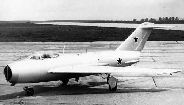
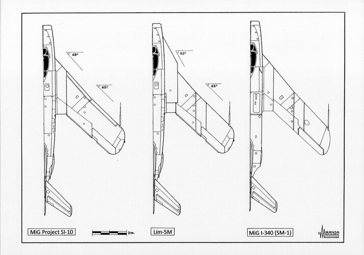
Having overcome in 1948 on a MiG-15 (I-310, C) fighter the thousand-kilometer speed limit in OKB-155, headed by chief designer A.I. Mikoyan, together with TsAGI specialists, almost immediately outlined measures to further improve it. Already on July 26, 1949, a prototype of the MiG-17 (I-330, SI) fighter rises into the air, on which, in comparison with its predecessor, the sweep of the wing along the 1/4 chord line was increased from 35╟ to 45╟ to reduce the effect of air compressibility and also used thinner aerodynamic profiles. In connection with the installation of a new wing on the MiG-17, the tail section of the fuselage and the tail unit were also subjected to corresponding revision. These measures made it possible, with the same as that of the MiG-15bis (I-317, SD) VK-1 engine with a thrust of 2700 kgf, to increase the maximum speed from 1076 km / h to 1114 km / h.However, it was clear that more powerful propulsion systems were required to achieve even greater speeds. Further carried out by the OKB-45 team of the chief designer V.Ya. Klimov's work on forcing the VK-1 engine made it possible to raise its thrust to 3380 kgf. The subsequent installation of an engine, called VK-1F, on the MiG-17F (SF) aircraft made it possible, without changing its aerodynamics, to increase the maximum speed of the fighter to 1145 km / h.It is necessary to pay attention to the fact that the use of a forced VK-1F engine instead of VK-1 was accompanied by a slight increase in maximum speed. If the thrust of the VK-1 in comparison with the RD-45F increased by 19%, and the speed of the MiG-15bis in comparison with the MiG-15 increased by 2.8%, then with an increase in the thrust of the VK-1F by another 25%, the speed of the MiG-17F in compared to the MiG-17, it has grown by the same 2.8%. This is due to the fact that even when the afterburner was turned on, the MiG-17F fighter in horizontal flight did not reach supersonic speeds. On state tests of an experimental aircraft, conducted at the Air Force Research Institute of the Air Force in 1953, the maximum number of M was reached equal to 0.998, which was determined by recalculating the data obtained and bringing them to the conditions of a standard atmosphere.

A more significant increase in maximum speed when using afterburner is obtained only when the aircraft reaches supersonic speed. In this case, with an increase in the number M, there is no intensive increase in the coefficient of profile and harmful resistance, which leads to a rather significant increase in the maximum speed. The aerodynamic layout of the MiG-17 clearly did not meet the requirements of supersonic flight.

In this regard, back in July 1949, the OKB-155 team began to develop an experimental aircraft in order to achieve the speed of sound. By the end of the year, the preliminary design of the new machine was brought to 70% readiness.

Meanwhile, in addition to OKB-45 V.Ya. Klimov, work on the creation of promising jet engines was also carried out by OKB-165 and OKB-300 teams, headed by AM Lyulka and A.A., respectively. Mikulin. In the early 1950s, OKB-155 developed three new fighters for the new jet engines TR-3A and AM-5 created by them.

The first of them, the front-line fighter I-350 , was built in accordance with the "Plan for experimental construction of aircraft for 1950-51", approved on June 10, 1950 by the Resolution of the Council of Ministers of the USSR and communicated to all co-executors by the order of the Ministry of Aviation Industry that followed on June 14. It was expected that the TR-3A engine installed on the aircraft with a thrust of 5200 kgf would provide it with a supersonic flight speed. In accordance with the assignment, the I-350 was supposed to have a maximum speed of 1200 ... 1300 km / h at an altitude of 5000 m, a practical ceiling of 16000 m, a flight range of 1100 km, and with outboard fuel tanks of 1500 km. The plane was supposed to gain altitude of 5000 m in 2 minutes. Armament was supposed either from one 37-mm and two 23-mm cannons or from three 23-mm cannons.

The front-line fighter was ordered to be built in two copies. Moreover, the first copy was to be equipped with the already existing Korshun radar station, and the second with the Izumrud station, the development of which at NII-17 was already coming to an end. In April 1951, the car was required to be presented for state tests. At the same time, the task for the development of an experimental aircraft was excluded from the experimental work plan of OKB-155, due to the fact that it was included in the plan for 1950-51. the I-350 fighter was similar in its flight data.

Meanwhile, design work on the creation of the I-350 in OKB-155 was launched back in August 1949, and the draft design of the new machine was ready by July of the next year. In June, the construction of a model of the aircraft and the manufacture of models for blowing in the TsAGI wind tunnels began, and in October, the construction of the first flight prototype and a machine for static tests.

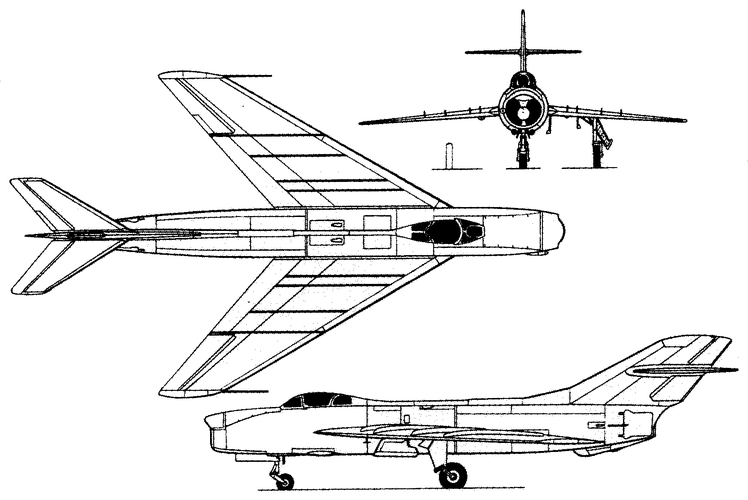
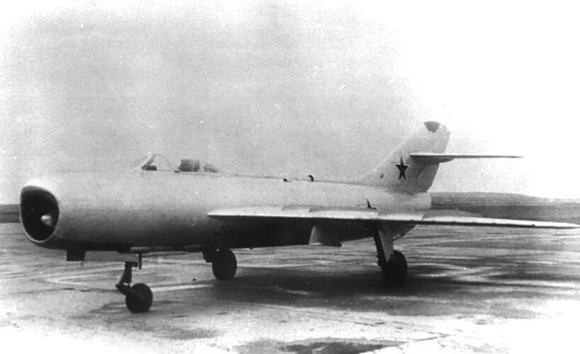
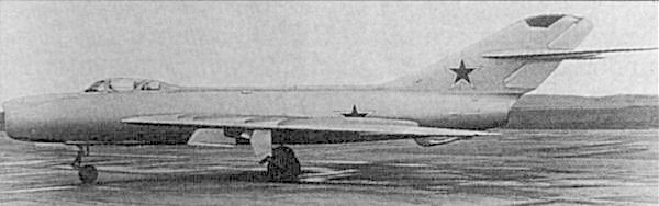
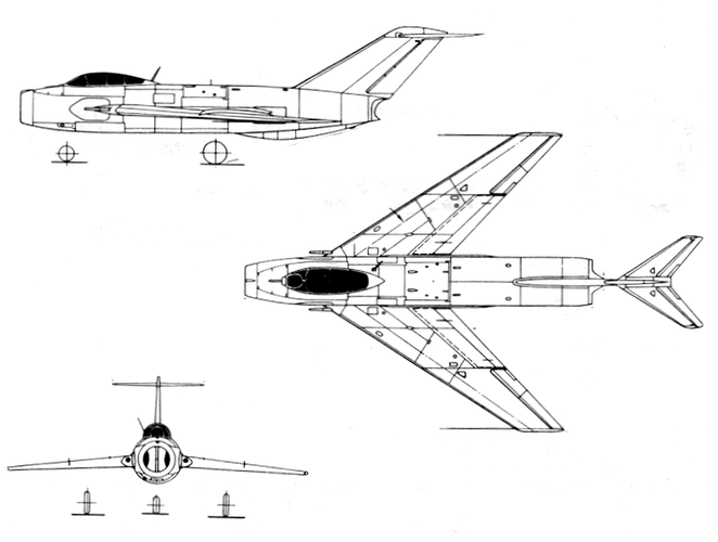
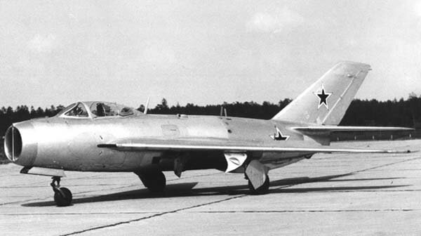
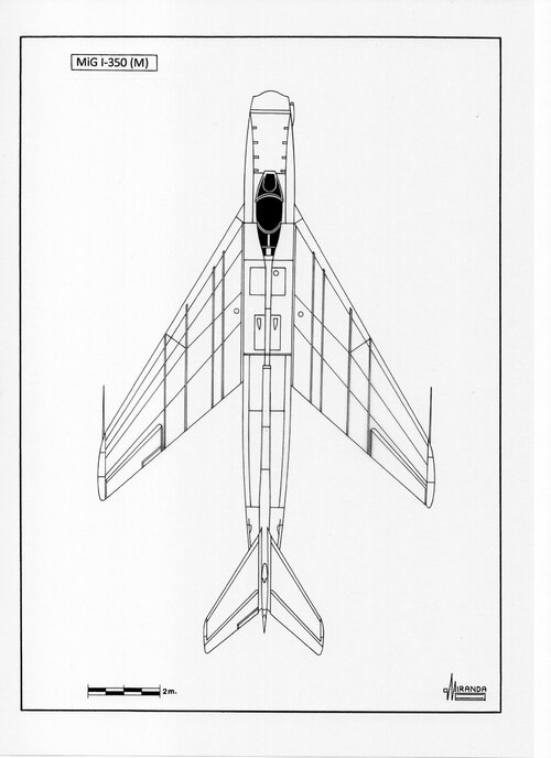
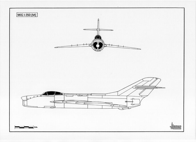
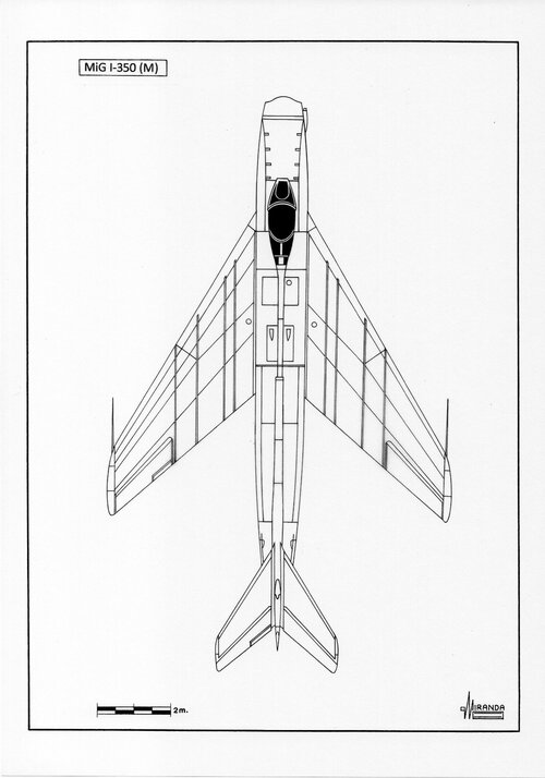
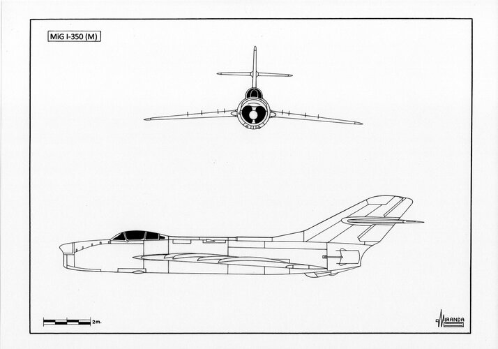
The I-350 fighter, which received the factory code "M", differed in many respects from its predecessors, and mainly in its aerodynamic layout, capable of providing confident supersonic flight.

The aircraft had a thin wing with a sweep of 57╟ and an aspect ratio of 2.6. To prevent air flow along the wingspan, four aerodynamic ridges were installed on the upper surface of each console. In view of the small thickness of the wing, the semi-forks of the main landing gear were located outside after cleaning and they were closed with special fairings placed on the wheel flaps. To reduce the mileage after landing, the aircraft was equipped with a braking parachute.

According to calculations, the I-350 with a take-off weight of 8030 kg should have had a maximum speed of 1240 km / h at the ground, 1244 km / h at an altitude of 5000 m and 1266 km / h at an altitude of 10,000 m.Its practical ceiling was estimated at 16600 m. m the plane was supposed to gain in 1.1 minutes, and 10,000 m - in 2.65 minutes. The fuel supply, located in two fuselage and six wing fuel tanks, provided a flight range of 1117 km. The use of outboard tanks increased the range to 1620 km.

On the first copy of the new aircraft, it was initially assumed, as required by the task, to install the Korshun radar. However, by this time, NII-17 had completed the development of a more promising Izumrud station, a prototype of which was installed in the summer of 1950 on an experimental MiG-15Pbis (SP-5) interceptor fighter for flight tests. Therefore, if good results were obtained during the tests, the designers provided for the possibility of installing the Izumrud radar also on the first I-350, which was later done. In addition to the radar station, the aircraft's special equipment included the RSIU-3 VHF radio station, the Bariy-M state recognition system and the OSP-48 blind landing equipment.

The armament of the I-350 fighter consisted of one 37-mm N-37 cannon with 50 rounds of ammunition and two 23-mm Sh-3 cannons with a total ammunition of 290 rounds. All cannon armament with ammunition was placed on a descending carriage, by analogy with the MiG-15 and MiG-17 fighters. The overload was provided for the suspension under the wing of two bombs with a caliber of 50 to 250 kg or two six-barreled launchers PU-85 for firing turbojet shells TRS-85. The aircraft's armor included 16-mm armor plate, 8-mm armored backrest, 16-mm armored headrest and 105-mm bulletproof glass.

To ensure the pilot's performance in the entire altitude range, the fighter was equipped with a sealed ventilation-type cabin. Flights at high altitudes were provided by the KP-14 oxygen device with three two-liter oxygen cylinders. The means of rescue were similar to those used on the MiG-15bis and MiG-17 aircraft.

In accordance with the directive schedule for the design and construction of the "M" product, approved by A.I. Mikoyan on June 28, 1950, the first copy of the I-350 fighter was supposed to leave the assembly shop by January 1, 1951. However, the given timeframe turned out to be unrealistic. The design and production of working drawings were completed only by the end of the year, and the technical readiness of the first flight prototype and the machine for statistical tests was 62%.

The fact that it would not be possible to meet the originally set deadlines became clear already at the beginning of August. This was due to the fact that the design of the aircraft had to be constantly changed. In particular, the Korshun radar station was replaced by the Izumrud station and the number of fuel tanks in the wing was reduced from six to four. In addition, static tests showed that the strength of the fuselage in the area of frame No. 18 is 90% of the design load, and this required additional measures to strengthen the aircraft structure. Therefore, it was necessary to adjust the work plan, and on September 2, the chief designer approved a new directive schedule, according to which the first car was to arrive at the airfield on January 30, 1951. Along with the first flight prototype, OKB-155 planned to start manufacturing a second aircraft in pilot production, which received the factory code "M-2". Her trials were to begin in May next year. However, in this case, too, the deadlines had to be shifted and by the end of the year the technical readiness of the M-2 was only 22%. In accordance with the schedule approved on March 24, 1951, the second prototype was supposed to go for testing on June 16, but this period was also soon postponed to September.

While OKB-155 was working on the manufacture of the I-350 aircraft, the state 100-hour bench tests of the TR-3A No. engine were completed with satisfactory results. 3A-165-11, the act according to which was approved by the Decree of the Council of Ministers of the USSR on March 28, 1951. By the same Decree, the TR-3A engine was named AL-5.

Meanwhile, to eliminate the phenomenon of surging in takeoff mode at negative values of the ambient air temperature, revealed during state tests in December 1950, for the TR-3A No. 3A-165-13 in February 1951, a new two-row guide vane of the 7th compressor stage was installed. But during control tests, the engine had to be stopped, as a large explosion of flame began from the jet nozzle. When disassembling it, it turned out that all the blades of the 7th stage compressor wheel had broken due to significant vibrations that had taken place.

By the time of the approval of the state testing act, the engine No. 3A-165-15, where a number of measures were taken to eliminate the identified deficiencies. In addition, engine No. 3A-165-10, the blades of the 7th stage of the compressor, including six reinforced ones, were subjected to strain gauging. However, the tests of the AL-5 No. 3A-165-10 showed that the performed strengthening of the blades did not give a significant reduction in stresses from vibration loads compared to unreinforced ones.

In connection with the revealed circumstances, OKB-165 specialists had to look for new design solutions. To eliminate the identified drawback, they developed six different measures, of which the best results were shown by turning the end sections of the blades of the 7th compressor stage at 4e and 7e (two options) towards a decrease in the angle of attack. Tests on AL-5 No. 3A-165-15 showed that vibration stresses decreased from 6 ... 7 kg / mm² to 1.2 ... 1.5 kg / mm². But based on the results obtained, the chief designer of AM Cradle decided to equip the 7th stage disc of the compressor of the engine No. 3A-165-15 version of the blades with a change in the 4th angle of installation and submit it for 100-hour tests to evaluate measures aimed at eliminating previously identified defects.

In addition, the AL-5 No. 3A-165-08 after a similar revision in May 1951 was sent to LII MAP for testing at the Pe-8 No. 42310 for the purpose of determining the surging margin and strain gauging of the compressor blades. Two flights performed in early June showed that at altitudes of 8000 m and 10000 m there are no surge phenomena at maximum speed. However, at an altitude of 8000 m, in take-off modes of engine operation, the phenomena of self-oscillations of a blade with a maximum value of stresses of about 3 kg / mm² were recorded.

While OKB-165 was solving the problems of its engine, in the experimental production of OKB-155, after finalizing the keel, stabilizer and fuselage, carried out according to the results of statistical tests, on May 31, 1951, the assembly of the first copy of the I-350 was completed. And already on June 1, the car was transferred to the OKB-155 flight station at the LII for factory tests. In accordance with the approved program, in the course of their implementation, it was planned to perform 93 flights, including 13 flights to prepare the aircraft for the air parade dedicated to the Air Fleet Day.

Due to the fact that after strengthening the aircraft structure, statistical tests of the tail were carried out only up to 90% of the design load, after which they had to be stopped for technical reasons, TsAGI specialists gave the following restrictions for the first copy of the I-350:​

  • velocity head no more than 6200 kg / m2 (calculated 6600 kg / m2).
  • the number M is not more than 1.1 (according to the calculation when diving Мв1.5, in horizontal flight М = 1.15).
It should be noted that the I-350 was powered by the AL-5 No. 3A-165-12, which, like AL-5 No. 3A-165-14 intended for La-190, was not accepted by the military representative of the ATK Air Force at plant No. 165 (OKB-165). The military representatives motivated the refusal to accept the engines by the fact that design changes had been made to these specimens in the form of installing an expanded turbine nozzle with a flow area of 1838.3 cm². Thus, they differed from the reference engine that passed the state 100-hour bench tests. And to accept engines with such an improvement without having to carry out long 100-hour reliability tests,

In this regard, the AL-5 No. 3A-165-12 was installed on the first prototype of the I-350 aircraft under the personal responsibility of the chief designer AM Lyulka, and at plant No. 165 began to prepare a new engine for OKB-155 - AL-5 No. 3A-165-20.

By the order of the Ministry of Aviation Industry of June 16, 1951, a brigade consisting of test pilot G.A. Sedov, leading engineer K.P. Kovalevsky, mechanic G.E. Pavlov and the minder M.A. Ryzhkov. On the same day, after the completion of the ground part of the tests and the elimination of the identified deficiencies, the first flight of the I-350 took place.

The plane behaved normally on takeoff. The climb 1800 ... 2000 m also passed without remarks. In flight, the speed was increased to 680 km / h on the instrument. However, in the 8th minute, when the engine was throttled at an altitude of 1800 m, it stopped. In this regard, test pilot G.A. Sedov had to land in an emergency vehicle in extreme conditions, since the failure of the power plant led to a malfunction of the hydraulic system, with all the ensuing consequences. But despite the current situation, the pilot managed to make a normal landing at the LII airfield. Fortunately, the emergency pneumatic system for the landing gear, flaps and brake parachute did not fail. Moreover, the chassis was released just a few seconds before landing.

It should be noted that the phenomenon of self-shutdown in flight of the AL-5 engine with a fuel pressure in front of the injectors of about 16 kg / cm² was also detected on the La-190 aircraft, which was undergoing factory flight tests at the airfield of the Air Force Research Institute of the Air Force.

In connection with the new circumstances for the continuation of flights, the chief designer of AM Lyulka set the following restrictions, which were required to be strictly observed during the operation of the AL-5:​

  • to reset the speed in flight from the maximum allowable to the minimum mode by smoothly moving the gas sector for at least 15 ... 17 seconds at altitudes up to 5000 m;
  • the minimum allowable fuel pressure in front of the nozzles in flight must be at least 20 ... 22 kg / cm² up to an altitude of 10,000 m;
  • when the aircraft descended for landing from an altitude of 300 ... 500 m, it was allowed to switch the engine to idle mode by smoothly moving the control lever.
Already on June 19, test pilot G.A. Sedov made the second flight to an altitude of 4000 m, observing the specified restrictions. The flight, which took 20 minutes, passed without comment, while the maximum speed was brought up to 750 km / h on the instrument. The next day G.A. Sedov, in a Pe-8 flying laboratory at an altitude of 4000 m and a speed of 300 km / h, checked the AL-5 operation with an instantaneous movement of the gas sector from 6600 rpm to 2500 rpm. In this case, the engine was running normally, and the minimum fuel pressure in front of the injectors was 12 kg / cm².

The analysis of the reasons for the self-shutdown of the AL-5 engine when flying at a speed of more than 500 km / h showed that the movement of the gas sector from maximum revolutions towards their decrease leads to a sharp depletion of the mixture (an increase in the excess air ratio) in the combustion chamber, exceeding the limit of stable combustion. In turn, a sharp depletion of the mixture in the combustion chamber occurred due to the regulator, which sought to reduce engine speed in accordance with the new position of the gas sector, by reducing the fuel supply. At the same time, the speed of the oncoming flow prevented the decrease in speed, the change in which depended on the time of the change in the flight speed. Since the regulator did not have a limiter for reducing the fuel pressure, it continued to reduce the fuel supply, moreover, to a greater extent than was necessary for the engine to operate at rpm, corresponding to the new position of the gas sector. And since the limit of stable combustion in the combustion chamber was not high enough, the combustion stopped even at a rather high fuel pressure (12 ... 14 kg / cm²), that is, with excess air ratios in the range of 30 ... 35.

Based on the analysis carried out, OKB-165 developed and submitted to the military representation an action plan to eliminate the phenomenon of self-shutdown of the AL-5 engine in flight, which provided for work in two directions:​

  • increasing the boundary of stable combustion in the combustion chamber when the mixture is depleted;
  • introduction into the design of the speed controller of an element that limits the drop in fuel pressure in front of the nozzles in flight to the minimum permissible limit at which the depletion of the mixture does not go beyond the boundary of stable combustion.
Due to the problems that emerged in the operation of the power plant, it was necessary to move away from the implementation of the I-350 factory test program and concentrate all work on studying the operation of the engine. In addition, by the decision of the chief designer A.I. Mikoyan in the experimental production of OKB-155 from June 21, 1951, work on the manufacture of the second flight copy of the I-350 fighter was stopped until the completion of the AL-5 engine. By this time, the readiness of the units of the M-2 machine was 90%.

In accordance with the aforementioned plan, on June 22nd, engine No. 3A-165-15 with a new version of the combustion chamber burners. For burners, designated EB-3408, the design of the body and swirler was changed, which made it possible to change the velocity field in front of the burners and the amount of air in the igniter zone. Due to these changes, it was supposed to increase the combustion stability. Preliminary tests of the burner at CIAM showed that the boundary coefficient was equal to 90 against the previously existing value of 30 ... 35.

After the completion of 25-hour bench tests, AL-5 No. 3A-165-15 without disassembly was sent to LII for installation on Pe-8 No. 42310. In flight in the flying laboratory, the engine worked steadily at altitudes up to 9500 m with a fuel pressure in front of the nozzles of 7 ... 11 kg / cm². At altitudes up to 8000 m at a flight speed of up to 300 km / h on the instrument, with a sharp cleaning of the gas sector in 0.5 seconds from the maximum mode to a fuel pressure of 4.2 ... 4.9 kg / cm², the engine did not turn off by itself. In addition, on the last day of June, the No.3 А-165-03 engine with new burners, which were supposed to provide stable combustion in the combustion chamber at higher coefficient values than the burners of the No. 3A-165-15.

Meanwhile, the AL-5 No. 3A-165-20 with the first version of the combustion chamber burners, and on June 28 it was sent to OKB-155 for installation on the I-350 aircraft. Two days later, control tests with the same burners and the AL-5 No. 3A-165-16 intended for La-190, and on July 2 it was sent to OKB-301. As instructed by AM A cradle in order to increase the combustion stability on the working injectors of both engines after they have been sent from factory No. 165 also installed caps to cover the annular gap between the burner and the nozzle.

While the experimental production of OKB-155 was changing the engine on the I-350 fighter, at plant No. 165 and LII continued testing engines No. 3A-165-03 and No. 3A-165-15. Moreover, the latter was additionally equipped with a special valve in order to maintain the minimum fuel pressure in front of the nozzles in flight. In addition, for a comprehensive assessment of all the improvements aimed at eliminating the phenomenon of self-shutdown, OKB-165 began to prepare the AL-5 No. 3A-165-18 for long-term 100-hour bench tests.

On bench tests, engine No. 3A-165-03 with the second burner version worked well, and a new mixer with a large number of holes installed on it made it possible to reduce specific fuel consumption by 2%. In addition, tests carried out at CIAM showed that such a mixer also contributed to an increase in combustion stability. However, disassembling the engine revealed a shift in the high temperature zone closer to the burners, which led to burnout of the mixers. And this, in turn, required further refinement.

In order to refine the speed regulator in OKB-165, in addition to the minimum pressure valve mentioned above, which showed unsatisfactory results, two more valve options were developed: a drain valve and a retarder valve. But on tests, the latter also showed unsatisfactory results. In this regard, in order to increase the stability of the regulation of the fuel supply to the engines intended for the I-350 and La-190 aircraft, only drain valves were installed.

Unlike AL-5 No. 3A-165-03 engine No. 3A-165-15 is out of luck. July 16 Pe-8 No. 42310 crashed while landing due to a broken left tire. The plane skidded, and it drove off the runway onto soft ground, which led to a chassis failure. Upon hitting the ground, the car caught fire, and it was not possible to save it. As a result of the fire at the AL-5 engine, the communications were burnt and there were burnouts from the external influence of the flame, in connection with which it was sent to plant No. 165 for disassembly and fault detection.

After installing the AL-5 No. 3A-165-20 on the I-350 fighter, test pilot G.A. Sedov performed two more flights on it, on July 17 and 19. They showed that the OP8049-00 drain valve, providing the minimum specified fuel pressures in front of the nozzles, along with greater stability of combustion in the combustion chamber, made it possible to eliminate the AL-5 self-shutdown defect in flight. After that, a new drain valve was installed on the engine, which improved the control characteristics.

On August 1, 1951, after the completion of the fuel system refinement, test pilot G.A. Sedov lifted the car into the air for the fifth time. The flight took place at altitudes up to 5000 m, and the speed was increased to 580 km / h by the instrument. At the same time, it turned out that at an altitude of 5000 m, when collecting gas to idle, the minimum engine speed was 5300 rpm, and when cleaning and dispensing gas, the engine sluggishly reached the set speed. The same results were obtained on August 4 on the La-190 aircraft, the tests of which were transferred to the LII, when at an altitude of 7000 m at a speed of 650 km / h on the instrument, after the gas sector was switched to idle, the minimum speed was 5700 rpm.

The results of both flights confirmed that the drain valve and new burners ensured that the engine operated without shutdown when cleaning the gas sector. However, the introduction of a drain valve into the fuel system brought about new problems. First, with an increase in flight altitude over 5000 m, idle speed increased unnecessarily. Secondly, the throttle response time increased to 60 seconds, and the engine sluggishly reached the set rpm.

To eliminate new defects, the regulator retarder ratchet was developed and sent for bench testing. At the same time, engine No. 3A-165-03 continued work to improve the stability of combustion and ensure the stability of the regulation of the fuel supply in flight at the minimum allowable pressure. In particular, a new version of burners with a diaphragm, which was a two-row grid located between swirlers and nozzles, with a reduced cross-section of holes and without a gap between the burner and nozzles, was developed and in August 1951 passed bench tests. On tests at CIAM, such a burner showed a further improvement in combustion stability. In addition, engine No. 3A-165-08 passed tests, albeit unsatisfactorily, a new version of the mixer.

After the completion of bench tests, the ratchet of the speed regulator retarder and a new version of the burners were planned to be installed on AL-5 No.No. 3A-165-12 and ZA-165-14, designed for the I-350 and La-190 aircraft, respectively. The assembly of these engines at factory No. 165 were supposed to be completed by mid-August. The chief designer of AM Lyulka guaranteed that the AL-5 engines with the indicated improvements would provide flight at all altitudes up to speeds corresponding to M-1.3 and at a minimum fuel pressure of 10 kg / cm². After receiving satisfactory results in flight tests, the AL-5 engine in the new layout was planned to be presented for 100-hour bench tests, which were provided for under the state program.

Unfortunately, it was not possible to solve the newly appeared problems on the move. The ratchet of the speed regulator retarder was rejected during tests and during debugging at the stand due to a number of structural defects identified. In this regard, in order to limit the drop in fuel pressure when the gas sector is switched to idle, OKB-165, instead of a ratchet, developed a new system with a valve that was included in the hydraulic part of the retarder servomotor.

The new development was tested on a bench for testing regulators and on the engine. Since it showed satisfactory results, by August 20, on the basis of the existing valves, the first copy of the retarder valve was assembled, manufactured according to new drawings, after which the unit, which received the name "MM idle valve", was sent to bench tests.

In late August, AL-5 No.No. engines were delivered for control tests. 3A-165-12 and ZA-165-14, on which, in addition to the modified combustion chamber (new burners with a double diaphragm, nozzles shifted by 3 mm towards the turbine, improved cooling of the mixers), MG-1 valves were installed. If satisfactory results are obtained in flight tests of these engines on an I-350 or La-190 aircraft, a similarly modified AL-5 No. 3A-165-18 was planned to be put on long-term 100-hour bench tests.

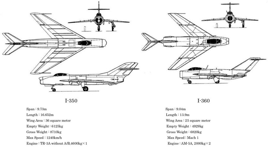
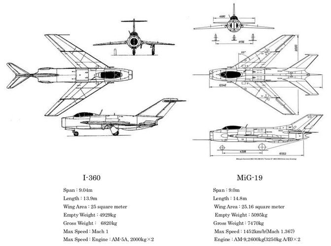
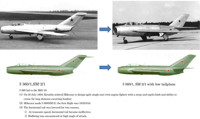
However, by this time, due to the "raw" engine, interest in the I-350 was gone. Already shortly after the last flight, by the Decree of the Council of Ministers of the USSR of August 10, 1951, work on the I-350 aircraft was officially terminated in connection with the start of work on the creation of the I-360 (SM-2) escort fighter with two AM-5 engines developed by OKB- 300 chief designer A.A. Mikulin.

Naturally, the production of the second copy of the I-350, the technical readiness of which was 75%, was not renewed, and the two-seater version of the fighter remained only on paper. The I-350 test program was completed by only 12%, and the vehicle was in the air for a total of about 1.5 hours.

Meanwhile, OKB-165 continued work on fine-tuning the AL-5 engine. After the elimination of a number of revealed defects on the first day of September, control tests of AL-5 No. 3A-165-14 designed for the La-190 aircraft, and on September 7 - AL-5 No. 3A-165-12 intended for the I-350. However, due to the termination of testing of both fighters, engines from factory No. 165 were not sent to OKB-301 and OKB-155.

In connection with the current situation, the chief designer of AM Lyulka made an attempt to achieve, through the leadership of the MAP, a solution to the issue of testing in flight conditions on aircraft of the OKB A.S. Lavochkin or A.I. Mikoyan's AL-5 engine with the latest revision. At the same time, factory No. 23, the re-equipment of the Tu-4 No. 230113 to a new flying laboratory designed to test the AL-5 engine, work on which was planned to be completed only by October 10.

Also in mid-September, the Deputy Commander-in-Chief of the Air Force, Major General of the IAS M.T. Shishkin sent a letter to the Deputy Minister of the Aviation Industry P.V. Dementieva with a request for an urgent continuation of flight tests of the La-190 aircraft with the AL-5 No. 3A-165-14 and the beginning of flight tests of the AL-5 No. 3A-165-12 on an I-350 aircraft in order to check measures to eliminate previously identified defects.

In a reply sent on October 18 by Deputy Minister S.N. Shishkin, it was reported that in-flight testing of the measures proposed by the design bureau of the chief designer AM Lyulka to eliminate defects in the AL-5 engine will be continued on the Tu-4 aircraft, the re-equipment of which into a flying laboratory was completed at the OKB-23 of the chief designer V.M. Myasishchev.

As for the use of the I-350 aircraft, S.N. Shishkin reported that this requires a government decision, since work on this machine was removed from OKB-155 in connection with the receipt of a new assignment. The tests of the La-190 aircraft were also temporarily stopped due to the fact that the Lavochkin Design Bureau received a special task from the Government, which is urgent. In turn, the AL-5 engines were installed on the newly built high-speed bombers - "150", developed in OKB-1, chief designer B. Baade and IL-46, created in OKB-240, chief designer SV. Ilyushin.

Therefore, it was planned to test the operation of the AL-5 engine at high flight speeds during flight tests of the indicated bombers.

Thus, the first attempt to create a supersonic fighter in the design bureau of chief designer A.I. Mikoyan was not crowned with success, however, the same fate befell the SA Design Bureau. Lavochkin with the La-190 aircraft. And the AL-5 engine was never put into mass production due to constantly arising problems, mainly caused by its poor layout. However, the experience gained by OKB-165 specialists during its development and fine-tuning served as a necessary basis for the creation of a more advanced AL-7 engine, which was put into mass production and used on domestic aircraft.​

Specs
Modification I-350
Wingspan, m 9.73
Length, m 16.27
Wing area, m2 36.00
Weight, kg
empty plane 6177
maximum takeoff 8030
fuel 1600
engine's type 1 TRD TR-3A
Thrust, kgf 1 x 5200
Maximum speed, km / h
by the ground 1240
on high 1266
Practical range, km
normal 1260
with PTB 1825
Rate of climb, m / s 4546
Practical ceiling, m 16600
Crew, people 1
Armament: one 37 mm N-37 cannon and two 23 mm Sh-3 cannons


In the Soviet Union, the attitude towards heavy twin-engine fighters capable of covering strategic bombers all the way to the target and back was not unambiguous. It was recognized that aircraft of this type are needed, especially in the 30s. The Red Army Air Force received a powerful fist from several heavy-bomber air corps equipped with four-engine TB-3. However, the Tupolev ANT-21 and ANT-29 remained in prototypes. Created by the beginning of the 40s. a new generation of heavy bombers (DB-A and TB-7), which had an even greater range, gave rise to the emergence of several projects of heavy escort fighters (OKO-6, VI-100, DIS, TIS, SAM-13 and a number of others). Despite the fact that by the beginning of World War II, some of them (for example, OKO-6) had successfully passed the tests, none of them, for various reasons, was never put into mass production. Later, it was not possible to develop anything similar to the American "Lightning" or the British "Mosquito".

At the same time, having received in the late 40s. powerful Tu-4s, the Soviet Air Force, in the event of a large-scale conflict with former allies, in fact, could not use them in daytime conditions at remote sites due to the lack of modern escort fighters. Of course, there were La-9 and La-11 as part of the fighter aviation, however, over the goals for which the Soviet "Superfortresses" were to work, they would have been awaited by the American jet F-80s. However, the potential enemy's picture was the same, if not worse: in the event of the start of deep raids of the B-29 formations according to the Dropshot plan, the latter would have to be covered with Mustangs and Thunderbolts, which would have been opposed by the MiG-9 and Yak- 15, and since mid-1949 and much more advanced MiG-15.

It was not possible to refuse escort fighters. The experience of the recent war testified that the tones of "Flying Fortresses" made to Germany without destructive cover were too expensive.

The creation of jet front-line bombers Il-28 and Tu-14, and later the long-range Tu-16, with transonic flight speeds only temporarily postponed the problem of providing cover, since the appearance of even faster interceptors in the arsenals of a potential enemy was only a matter of time. Introduced into service in mid-1949, the MiG-15 was a completely modern machine designed to gain air superiority, but by no means an escort aircraft, and its adaptation to this role was extremely difficult.

An attempt to create the Burlak system (towing MiGs with four-engine Tu-4s) turned out to be almost unpromising, since the fighters walking on a leash did not have the necessary speed reserve or altitude to instantly parry the enemy's interceptor attacks. Mock battles showed that from the moment the attacking aircraft were detected, to the organization of counteraction by the forces of the towed MiG-15, the enemy manages to make two or three attacks in the formation of bombers. In the event of a combined strike against the carriers, the strategic formation risked generally remaining over enemy territory without a fighter "umbrella". Not everything was smooth with the accompaniment of the latest Il-28 and Tu-14. The main disadvantage of the MiG-15 was the low maximum permissible speed with outboard fuel tanks (PTB), which at an altitude of 5000 m was only 17-38 km / h, and at 10000 m - 23-47 km / h. A new level machine was required, and on July 30, at a meeting in the Kremlin, J.V. Stalin raised the issue of creating a fighter with a range greater than that of the MiG-15 and MiG-17.

According to the plan developed "at the top", it was planned to develop two-engine vehicles of two types: an all-weather interceptor with a powerful on-board radar and a maneuverable supersonic front-line fighter with a high rate of climb and a flight range of at least 2,000 km. It was assumed that the latter would carry out a flight to escort bombers, using an economical mode on one operating engine, and air combat would be conducted on two. In addition, it was required not only to work out the aerodynamic scheme, but also to create new powerful and economical engines.

It was clear that two bulky turbojet engines with centrifugal compressors `` would not fit '' into the dimensions of the fighter fuselage, moreover, it turned out that their gas-dynamic characteristics would not allow achieving the specified fuel consumption parameters and soon the need to switch to engines with axial compressors for the OKB-155 A team I. Mikoyana became obvious. They decided to make a bet on AM-5, the refinement of which was completed at the A.A. Mikulin Design Bureau.

For research and the fastest fine-tuning of the power plant on the basis of the MiG-17F in 1951, an experimental I-340 fighter (product SM-1 ) was created, which actually became a flying laboratory. At the end of the same year, OKB test pilots G.A. Sedov and K.K. Kokkinaki performed a number of flights on it. A.V. Minaev was appointed the lead testing engineer. Subsequently, he recalled: ╚The success of the MiG-19 was largely predetermined by the accelerated fine-tuning of the engines in the air. Of course, there were some troubles, and the engine blades were torn off, and what not happened.

The SM-1 differed from the MiG-17 in the tail section of the fuselage, where instead of the VK-1, two AM-5s with a thrust of 2000 kgf were placed, later replaced by the AM-5A giving 2150 kgf each (it was assumed, but the installation of the AM-5F was not implemented with afterburners). The small dimensions of the engines (compared to the VK-1F) made it possible to place three additional fuel tanks in the fuselage with a total volume of 770 liters. On tests, the SM-1 reached a maximum speed of 1193 km / h at an altitude of 5000 m, and its vertical speed was 40.6 m / s. Thanks to more economical "engines" and a larger supply of fuel, the range has significantly increased. As a result, the flight qualities of the SM-1 surpassed the MiG-17F, but the question of its serial construction was not even raised.

In the same period, the A.M. Lyulki Design Bureau developed a powerful turbojet engine TR-3A with an axial compressor. For it, OKB-155 created an experienced I-350 fighter (product ╚M╩). The aircraft had a 55╟ swept wing along the 1/4 chord line. Already the first flight, performed on June 16, 1951 by GA. Sedov, almost ended in an accident: at the last turn before the landing glide path, the engine stopped. The pilot managed to reach the runway, but when the landing gear was released, the right pillar did not lock, and literally a moment before touching the ground, Sedov “greeted” it from the emergency pneumatic system. Unstable combustion of fuel in the combustion chamber became the cause of engine failure. This deficiency could not be eliminated, and after five flights, the development of the I-350 was stopped.

Meanwhile, the power plant tested on the experimental SM-1 with two AM-5A engines without afterburners was completely transferred to the new I-360 escort fighter , which was created in accordance with the decree of the Council of Ministers of the USSR ╧2929-1379 of August 10, 1951.

The general management of the topic was headed by the Deputy Chief Designer A.G. Brunov. A.A. Chumachenko dealt with issues of aerodynamics, the control system and general issues of management - R.A. Belyakov. The head of the brigade G.E. Lozino-Lozinsky supervised the linking of the power plant, and D.N. Kurguzov supervised the strength calculations. The designer A.V. Minaev also played an important role in the creation of the future fighter. The draft design of the aircraft, which was assigned the product code SM-2 , began to be developed back in June (before the government decree was issued). Work on it was carried out at a very fast pace and was completed in December.

Four months after receiving the assignment, the draft design of the aircraft was defended. If the SM-1 was actually a modification of the MiG-17F, then the SM-2 became a fundamentally new machine, although much of it was used from previous aircraft. The fighter was a twin-engine midwing plane with a T-shaped tail. Among the technical innovations used on it, first of all, were a supersonic wing with a large sweep (55╟ along the line of 1/4 chords) and a smaller, compared to the SM-1 and MiG-17, span with one aerodynamic ridge on each console, aerodynamic the layout of which was developed at TsAGI. The wing had a negative lateral V = -40╟ 30 'and was collected from velocity profiles with a relative thickness at the root of 8.73% and at the end - 8.0%. Aileron control unit, worked out on the experimental I-350 (╚M╩) and the MiG-15 (╚SE╩) flying laboratory, fit into the small dimensions of the thin wing. The fuselage became 1.6 m longer. The horizontal tail (also with a sweep of 55╟ along the line of 1/4 chords) was moved to the top of the keel (the sweep of the latter was 56╟). The single-glass canopy with improved visibility had a slightly elongated shape, its cover, like on previous machines, was moved back. The ejection seat was equipped with a curtain to protect the pilot's face, which was lowered before the ejection. The composition of weapons has also changed. The horizontal tail (also with a sweep of 55╟ along the line of 1/4 chords) was moved to the top of the keel (the sweep of the latter was 56╟). The single-glass canopy with improved visibility had a slightly elongated shape, its cover, like on previous machines, was moved back. The ejection seat was equipped with a curtain to protect the pilot's face, which was lowered before the ejection. The composition of weapons has also changed. The horizontal tail (also with a sweep of 55╟ along the line of 1/4 chords) was moved to the top of the keel (the sweep of the latter was 56╟). The single-glass canopy with improved visibility had a slightly elongated shape, its cover, like on previous machines, was moved back. The ejection seat was equipped with a curtain to protect the pilot's face, which was lowered before the ejection. The composition of weapons has also changed.

Even during the tests of the first Soviet jet fighter, the MiG-9, it was found that firing from cannons located near the air intakes negatively affects the operation of the power plant. The air flow, disturbed by the propellant gases and falling on the blades of the axial compressor at an angle of attack different from the calculated one, was torn off, leading to a surge. On the MiG-15 and MiG-17 engines were installed with a centrifugal compressor, less sensitive to uneven flow, which determined the layout of the weapon. During the development of the CM-2, these problems arose again. One of the armed men, N.I. Volkov, proposed to transfer the guns to the wing. As a result, instead of the three cannons previously (on the MiG-15 and MiG-17) were placed on a monitor mount in the forward fuselage, on the SM-2, two N-37Ds were installed at the root of the wing with an ammunition capacity of 100 rounds each. At the same time, the layout of the new escort fighter retained some of the MiG-17 features.

Three copies of the aircraft were laid in the construction (two for flight and one for statistical testing). The SM-2/1 was equipped with serial AM-5 engines. On April 26, 1952, the first prototype of the I-360 fighter (product SM-2/1) was transported to the LII airfield, and on May 24, OKB test pilot G.A. Sedov took it into the air. During the period from May 24 to September 28, 46 flights were performed and the aircraft's flight and tactical characteristics were removed, but due to the lack of knowledge of the engines, flight tests could not be completed, and on September 30 the aircraft was returned to the plant. After installing new engines, the SM-2/1 arrived again at the flight test station on November 14, 1952.

In total, by the end of the year, the aircraft made 55 flights with a total flight time of 40 hours and 30 minutes. With a small angle of descent, the machine entered supersonic, reaching a speed corresponding to the number M = 1.16, and in horizontal flight at altitudes of 10000-11000 m - M = 1.045. The maximum indicated speed was 1200 km / h, and the maximum true speed at an altitude of 3000 m was 1225 km / h (according to the instructions, this speed was required to be obtained at an altitude of 5000 m). The maximum true speed at an altitude of 7000 m reached the value of 1180 km / h, although, again, this value no TT3 had to be reached at an altitude of 10,000 m. The new fighter climbed 10 km in 2.7 minutes (instead of the specified 3 minutes). The service ceiling was 16,400 m (which was 400 m higher than the target). The range of the new escort fighter without outboard tanks during tests reached 2005 km (less than the specified one by 95 km), and with outboard tanks - 3300 km (less than the predetermined one by 300 km). Nevertheless, the report on factory tests stated that the I-360 (SM-2/1) significantly surpasses all known fighters in its characteristics. It was noted that the aircraft can also be used as a front-line fighter and reconnaissance aircraft, and when installing the Izumrud radar - and as an interceptor. It was possible to fly with one engine running. Takeoff and landing properties did not differ from similar characteristics of other fighters, but sufficient effectiveness of the braking parachute was noted. Nevertheless, the report on factory tests stated that the I-360 (SM-2/1) significantly surpasses all known fighters in its characteristics. It was noted that the aircraft can also be used as a front-line fighter and reconnaissance aircraft, and when installing the Izumrud radar - and as an interceptor. It was possible to fly with one engine running. Takeoff and landing properties did not differ from similar characteristics of other fighters, but sufficient effectiveness of the braking parachute was noted. Nevertheless, the report on factory tests stated that the I-360 (SM-2/1) significantly surpasses all known fighters in its characteristics. It was noted that the aircraft can also be used as a front-line fighter and reconnaissance aircraft, and when installing the Izumrud radar - and as an interceptor. It was possible to fly with one engine running. Takeoff and landing properties did not differ from similar characteristics of other fighters, but sufficient effectiveness of the braking parachute was noted. It was possible to fly with one engine running. Takeoff and landing properties did not differ from similar characteristics of other fighters, but sufficient effectiveness of the braking parachute was noted. It was possible to fly with one engine running. Takeoff and landing properties did not differ from similar characteristics of other fighters, but sufficient effectiveness of the braking parachute was noted.

In addition to determining flight and tactical characteristics, in the process of carrying out factory tests, a flight was performed to escort an experienced Tu-16 bomber. The flight was performed at an altitude of 10,000-11,000 m at a speed of 900-950 km / h. The escort was carried out at a distance of 1500 m from the bomber with an altitude increase of 1000 m (in this flight, no suspended tanks were installed on the SM-2/1), while the attack of a single MiG-17 fighter entering from the rear hemisphere was repelled.

In the course of factory tests, the stability and controllability of the fighter in different modes was also studied. According to testers at medium speeds, these characteristics turned out to be even better than the MiG-15 and MiG-17, but the results obtained at the maximum flight speeds made it necessary to make a decision on the need to radically improve the efficiency of longitudinal control (by using a controlled stabilizer) and lateral control ( by introducing ingerceptors). Among other shortcomings, the lift-off speed (by 30-40 km / h) and landing speed (by 20-30 km / h) increased in comparison with the MiG-17 fighter.

In 1952, the second prototype of the escort fighter was produced (product SM-2/2). Unlike the first one, guns with long three-chamber muzzles were immediately installed on it, and to protect against the effects of powder gases when firing from the guns, small linings were made on the fuselage, in addition, the brake flaps were slightly increased in area. The car arrived at the flight test station on September 12, and G.A. Sedov made the first flight on it on September 28. From that day to January 28, 1953, work was mainly carried out on fine-tuning the engines, checking the effectiveness of the brake flaps of an increased area, as well as shooting weapons.

On February 24, the institute officially accepted the prototype vehicle for state tests, which began the next day. The leading engineer for the aircraft was V.V. Melnikov, and the leading test pilot was V.G. Ivanov. Pilots of the Air Force Research Institute V.S.Kotlov and A.P. Suprun also took part in the flyby of the machine. However, on March 6, the tests were interrupted. VG Ivanov, who rose that day on the prototype, when performing turns-spirals, reached an angle of attack close to the limit. At this moment, the air stream seemed to “catch” the car. The angle of attack of the aircraft, which did not react to the deflection of the elevator, began to increase sharply. The sudden large overload that had arisen also abruptly disappeared, and the plane fell into a tailspin, in which the car fell almost 8000 m (!), But nevertheless the flight ended safely. It turned out,

During the tests, a shaking of the stabilizer was also discovered, which, in some flight conditions, found itself in the area of the air flow disturbed by the wing. In addition, it turned out that the height of the aerodynamic ridges on the wing is clearly insufficient. The increased thickness of the boundary layer at the wingtips led to a decrease in the efficiency of the ailerons and premature stall of the flow. Disadvantages were also revealed in the fuel automation system. It was concluded that the aircraft needed serious improvements. The car was returned to the factory for rework.

The designers had to conduct additional research in the wind tunnel, according to the results of which it was decided to perform a number of improvements on the SM-2/1. But even before they began, a second plane was used to find out the reasons for the loss of longitudinal stability at high angles of attack. Research carried out on the CM-2/2 from March 13 to April 10, 1953. included eight flights at an altitude of 12,000 m with various options for aerodynamic ridges on the wing and flats on the fuselage, as well as with flaps extended and aileron deflected upward. However, these measures did not give results, but only modified the nature of the loss of stability and control at high angles of attack. In all cases, the car lost longitudinal stability, began to converge, and then fell into a spin. April 10 to May 8, 1953 SM-2/2 was at the experimental plant OKB-155, where it underwent the same alterations as SM-2/1. The main ones were as follows:​

  • the horizontal tail was lowered onto the fuselage, while its area increased from 3.47 m2 to 5.5 m2;​
  • improved the upper tip and lower keel base, and increased the rudder area;​
  • the fuselage was modified - on frames 33 and 36, the horizontal tail attachment points were installed (two on each side), and a hole was made in the skin between frames 34 and 35 for the passage of the stabilizer beam;​
  • in connection with the transfer of the horizontal tail downward in order to avoid the appearance of shaking when opening the brake flaps, they were moved forward, closer to the wing (between frames ╧22 and 26,) and lowered down with a simultaneous increase in the area to 1.07 m2; the shields deviated at an angle of 50╟;​
  • the reversible booster system for elevator and aileron control was replaced with an irreversible one;​
  • installed new equipment of state recognition "Uzel".​
As a result, the weight of the SM-2/1 increased by 150 kg.

On May 9, repeated control factory tests of both prototypes began, which were carried out by OKB-155 test pilot G.A. Sedov. Although from the very beginning it became obvious that the developers' work was not in vain, in general the tests were rather difficult. In one of the flights on SM-2/1 at G.A. Sedov at an altitude of 500 m, the speed of first one, then the second engine, with a significant fuel remaining, depended. Turning around quickly, the pilot was able to land at his airfield, however, at the very end of the runway. The plane with landing gear struts hooked on the airfield fence, destroying it, but he himself received practically no damage!

Whatever it was, but on June 25, the tests ended. Somewhat earlier (June 21), the SM-2/2 program “flew off”, on which the longitudinal stability was tested at high angles of attack with a changed position of the horizontal tail, and the flight-tactical characteristics were also taken. In total, during 1952-1953. Sedov performed over 130 flights on both prototypes.

Already in the process of testing on both machines, the height of the aerodynamic ridges was increased almost three times, which made it possible to eliminate the overflow of the air flow. Together with the alterations indicated above (according to the estimates of specialists who carried out factory tests of the modified SM-2), this made it possible to significantly improve the longitudinal stability and controllability of the fighter at high angles of attack. The transfer of the horizontal tail ensured good longitudinal control of the vehicle over the entire range of angles of attack (up to a spin). At the same time, the main characteristics of the aircraft have hardly changed. So, the true speed in the entire range of altitudes decreased by 10-15 km / h. The flight range with outboard tanks was 3238 km, and without them - 1925 km. Service ceiling and climb rate were not measured.

On July 18, 1953, the state tests of the modified SM-2/1 were resumed. The leading pilots were Lieutenant Colonels V. Givanov and A.P. Suprun, the fly-over pilots were Colonels Antipov and Kuvshinov, Lieutenant Colonels V.S. Kotlov and A. Rogatnev, Major Kipelkin and Captain Dzyuba. V.V. Melnikov remained the leading engineer for the aircraft. The assessment of the capabilities of the converted machine, however, turned out to be much more modest compared to that given by the factory workers. The military quickly established that the previously existing defect associated with longitudinal instability at high angles of attack in a wide range of possible overloads had not been completely eliminated. For this reason, it was considered unsafe to perform aerobatics at altitudes below 9000-10000 m. It was also noted that pitching instability during air combat can lead to a disruption of the attack.

On October 16, the Air Force Research Institute completed the determination of the tactical flight characteristics of the modified fighter. It was not possible only to test the weapons in flight, since the N-37D cannons were removed from the plane. The military's claims also concerned the control system of the fighter. Control of the SM-2 aircraft, in case of failure of the main system, was duplicated, and the stabilizer control system contained an automatic control for changing the efforts on the handle and a mechanism for changing the gear ratio from the handle to the stabilizer (the world's first electric automatic control regulation -

AGC). To simulate efforts, the control handle was loaded with special springs. Initially, the plane had two springs. With one, piloting was carried out with the landing gear retracted, with two - with the released. Switching the springs was locked by the position of the chassis and was carried out automatically. In the control system of the ailerons and elevator, hydraulic boosters switched on according to an irreversible scheme were used, installed in the process of finalizing the experimental SM-2 (before that they were switched on according to a reversible scheme). To improve controllability on the lower surface of the wing, spoilers were installed in front of the flaps, kinematically connected to the ailerons. A.G. Solodovnikov, who was one of the test pilots of the Air Force Research Institute of the Air Force at that time, recalled:

╚This character of control loading was acceptable for the pilot at speeds close to sound, where increased rudder consumption is required, and when flying with the landing gear extended, where rudder consumption is low. At a speed of 700-900 km / h, the pilot required increased attention to maintaining the specified mode. The aircraft became very sensitive to longitudinal deflection of the handle, and it could be easily rocked vertically.

Once Lieutenant Colonel A. Rogatnev, having completed the task in the zone, turned towards the airfield and released the brake flaps. The fighter lifted its nose slightly. In an effort to keep him in straight flight, the pilot slightly deflected the control stick away from him, but the plane suddenly pecked down and went into negative overload. The pilot found himself at some point in a state of weightlessness and, trying to get out of this situation, instinctively took the handle over himself. The fighter took off again with a large positive G-force, literally pushing its "owner" into the seat. Later, Rogatnev said: ╚It seemed to me that I slightly gave the handle away from me, but the car went down sharply again ... again the handle was taken over and the plane again rushes upwards ... шись Having hit his head on the glazing of the lantern, Rogatnev involuntarily grabbed hold of hands behind the sides of the cabin, releasing the control handle. A moment - and the car froze in horizontal flight. Taking it carefully and trying not to rock the fighter, the tester gradually reduced speed, reducing the effectiveness of the elevator and soon landed at the airfield.

The flights on the experimental SM-2 showed that supersonic aircraft should be equipped with fundamentally new control systems. And yet the designers managed to solve a number of important problems. These included, in particular, the surge of engines and their stop in the air. In connection with significant changes in the longitudinal stability margin during flights at supersonic speeds, the need for an even greater increase in the efficiency of the horizontal tail was revealed. As a result, the Act based on the results of State tests contained, although not too long, but a rather weighty list of shortcomings of the new aircraft:​

  • unsatisfactory maneuverability at high altitudes (at g-load values close to the limit, the speed dropped sharply);​
  • poor acceleration characteristics (also at high altitudes);​
  • the practical ceiling for the suspension of additional underwing tanks was 13,600 m, which limited the possibility of escorting the Tu-16 bomber at its operating altitudes;​
  • unsatisfactory operation of the Radal-M rangefinder and the ASP-4NM sight;​
  • poor takeoff and landing characteristics, etc.​
Some of them were in some way a continuation of the merits of the fighter. For example, the pilots of the Air Force Research Institute noted that the SM-2 cockpit is wider than on the MiG-17, but the view of the front hemisphere is unsatisfactory due to the wide bindings of the visor and the sliding canopy cover. The car steered steadily, but behaved more inertly on the runway compared to the MiG-17. Takeoff proceeded normally, but with a longer takeoff run. A sluggish acceleration of the fighter was noted (from an initial speed of 380 km / h to a speed of 450 km / h, the SM-2/1 accelerated in 2 minutes 18 seconds, and the MiG-17F - in 1 minute 22 seconds). In flight, when passing through the transonic zone, no noticeable changes in stability were observed. Lateral stability was satisfactory. The behavior of the aircraft during the landing approach did not cause any complaints either: stability on the glide path of descent and mileage was assessed as normal. During the entire test period, three pairs of AM-5 engines were installed on the SM-2/1. According to the recall of the military, firing from cannons (tested on SM-2/2) did not affect the operation of the power plant, however, an unreliable launch on the ground was noted. But, of course, against the background of the speed data and the range demonstrated by the new fighter, all these shortcomings simply faded away (Table 1).

The state tests of the SM-2/1, carried out at the airfields in Chkalovsky and Vladimirovka, ended on December 15, 1953. Considering the novelty of the aerodynamic scheme of the aircraft, as well as the possibility of its improvement by installing more powerful engines, the State Commission in its conclusions considered it possible to recommend the SM -2 for adoption as an escort fighter, but only after eliminating all the shortcomings.

However, the Air Force command was quite optimistic in terms of fine-tuning and introducing the aircraft into the series. This is evidenced by the "Instruction GK-151 on balancing the SM-2 aircraft in military units" published by the Office of the Air Force Commander-in-Chief. However, it was possible to solve the problems of increasing flight stability and improving the controllability of the aircraft only by installing a stabilizer controlled in flight. Such studies were carried out in OKB-155 even in the process of designing the SM-2. Under the leadership of Deputy Chief Designer A.G. Brunov and Head of Department R.A. Belyakov, an irreversible booster control was developed for a variant of a fighter with an all-turning stabilizer (without an elevator). To eliminate the entire set of shortcomings identified during the tests,​

Specs

Modification I-360
Wingspan, m 9.04
Length, m 13.90
Wing area, m2 25.00
Weight, kg
- empty plane 4718
- maximum takeoff 6820
- fuel 1825
engine's type 2 turbojet engine AM-5
Thrust, kgf 2 x 2000
Maximum speed, km / h 1153
Practical range, km
- normal 1620
- with drop tank 2700
Rate of climb, m / min 3846
Practical ceiling, m 15200
Crew, people 1
Armament:
- two 37-mm guns N-37 (ammunition 100 and 150 rounds).
- two bombs up to 250 kg or two ARS-57M rocket launchers
 
Last edited:
Development of a combat-capable supersonic fighter began in accordance with the Soviet Council of Ministers resolution dated June 10, 1950, under the codename MiG I-350 (M).

The new plane was fitted with 57-degree (25 % chord) swept wings, with four fences each, and powered by one Lyulka VRD-5 axial-flow turbojet rated at 4,500 kg static thrust.

The prototype was flown on June 16, 1951 but the pilot was forced to make an emergency landing because an engine flame out.

The project was cancelled (due the usual failure of the Lyulka engines) after only five flights.

MiG I-350 (M) technical data

Wingspan: 31 ft. (9.48 m), length: 54.6 ft. (16.65 m), height: 13.4 ft. (4.08 m), wing surface: 400 sq. ft. (36 sq. m), take-off weight: 17,660 lb. (8,000 kg), estimated maximum speed: 771 mph (1,240 km/h), estimated service ceiling: 52,480 ft. (16,000 m).
 

Attachments

  • 745.jpg
    745.jpg
    412.3 KB · Views: 142
  • 746.jpg
    746.jpg
    333.5 KB · Views: 140
Development of a combat-capable supersonic fighter began in accordance with the Soviet Council of Ministers resolution dated June 10, 1950, under the codename MiG I-350 (M).

The new plane was fitted with 57-degree (25 % chord) swept wings, with four fences each, and powered by one Lyulka VRD-5 axial-flow turbojet rated at 4,500 kg static thrust.

The prototype was flown on June 16, 1951 but the pilot was forced to make an emergency landing because an engine flame out.

The project was cancelled (due the usual failure of the Lyulka engines) after only five flights.

MiG I-350 (M) technical data

Wingspan: 31 ft. (9.48 m), length: 54.6 ft. (16.65 m), height: 13.4 ft. (4.08 m), wing surface: 400 sq. ft. (36 sq. m), take-off weight: 17,660 lb. (8,000 kg), estimated maximum speed: 771 mph (1,240 km/h), estimated service ceiling: 52,480 ft. (16,000 m).
Excellent drawings.
 
MiG I-350 (M)

On August 5, 1948, one RB-29 spy plane penetrated deep into Soviet airspace on a reconnaissance mission overflying Siberian airfields and radar sites.

The US Air Force Directorate of Intelligence recommended a program of border reconnaissance flying outside Soviet territory, using oblique photographic techniques. Some Boeing RB-29 and PB4Y2 Privateer long range spy planes were used in Electronic Intelligence (ELINT) missions over the Baltic Sea and the Sea of Japan and one RF-80A from Misawa AFB was used in photographic sorties over Sakhalin and Kuril Islands on May 10, 1949, and over Vladivostok between March 10 and August 18, 1950.

The British were also highly active using their Lincoln bombers in ELINT sorties over Soviet territory. Some Meteor PR.10 and D.H. Venom spy planes were used for photographic sorties over the East German border; the Spitfires PR.XIX flew at high altitude over Hainan Island, Murmansk, and Baltic States; one Mosquito PR.34 was flown over Ukraine from an airfield in Iraq, and some D.H. Chipmunk light planes were flying at low level over Soviet installations at Berlin Control Zone corridor.

Some Swedish Spitfires PR.XIX based at Lulea and Nyköping flew at 40,000 ft. over the Soviet-Finnish border carrying SKa10 and SKa12 cameras. But they had no information about what was going in the vast interior of the U.S.S.R. territory.

Between 1951 and 1955, the SAC RB-36s undertook peripheral sorties around USSR airspace but all the flights were detected by Soviet radar sites in Murmansk, Siberia, Armenia and Caucasus.

Development of a combat-capable supersonic fighter began in accordance with the Council of Ministers resolution dated June 10, 1950, under the codename MiG I-350 (M).

The new plane was fitted with 57-degree (25 % chord) swept wings, with four fences each, and powered by one Lyulka VRD-5 axial-flow turbojet rated at 4,500 kg static thrust.

The prototype was flown on June 16, 1951, but the pilot was forced to make an emergency landing because an engine flame out.

The project was cancelled (due to the usual failure of the Lyulka engines) after only five flights.

MiG I-350 (M) technical data

Wingspan: 31 ft. (9.48 m), length: 54.6 ft. (16.65 m), height: 13.4 ft. (4.08 m), wing surface: 400 sq. ft. (36 sq. m), take-off weight: 17,660 lb. (8,000 kg), estimated maximum speed: 771 mph (1,240 km/h), estimated service ceiling: 52,480 ft. (16,000 m).

According to the calculations of the TsAGI, a supersonic fighter would need at least 4,000 kg static thrust to reach Mach 1. The designers only had the option of using two Mikulin AM-5A axial-flow turbojets rated at 2,000 kg thrust each, because the available centrifugal-flow engines were too thirsty and too bulky.

To test the concept, a production MiG-17 was modified (decree April 20, 1951) with two AM-5A turbojets mounted side by side, under the codename MiG-17 SM-1 (I-340).

The prototype was flown in December 1951 reaching 1,193 km/h.

During test program the engines were replaced by two AM-5F with afterburning rated at 2,700 kg each.

MiG-17 SM-1 (I-340) technical data

Wingspan: 31.5 ft. (9.6 m), length: 36.9 ft. (11.26 m), height: 12.4 ft. (3.79 m), wing surface: 251 sq. ft. (22.6 sq. m), take-off weight: 11,500 lb. (5,210 kg), maximum speed: 741 mph (1,193 km/h), service ceiling: 51,168 ft. (15,600 m).
 

Attachments

  • pp.jpg
    pp.jpg
    427.3 KB · Views: 45
  • pi.jpg
    pi.jpg
    247.2 KB · Views: 49
  • po.jpg
    po.jpg
    339.3 KB · Views: 49

Similar threads

Back
Top Bottom