- Joined
- 18 March 2013
- Messages
- 970
- Reaction score
- 2,806
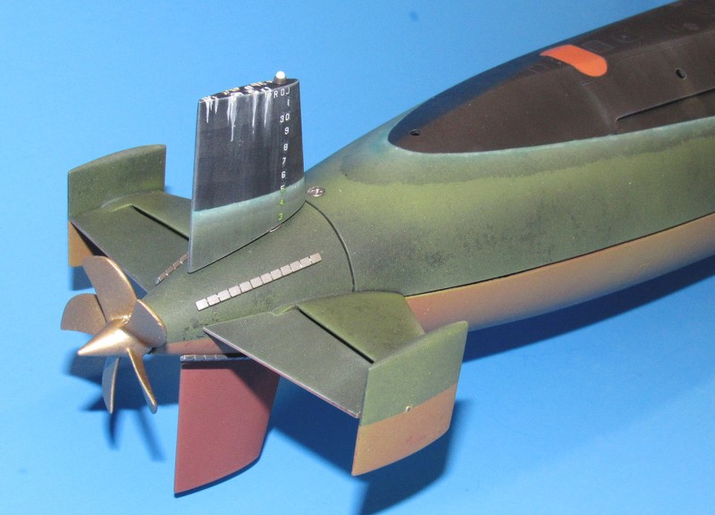
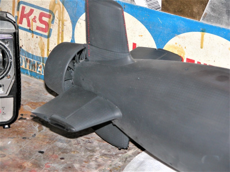
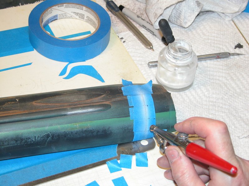
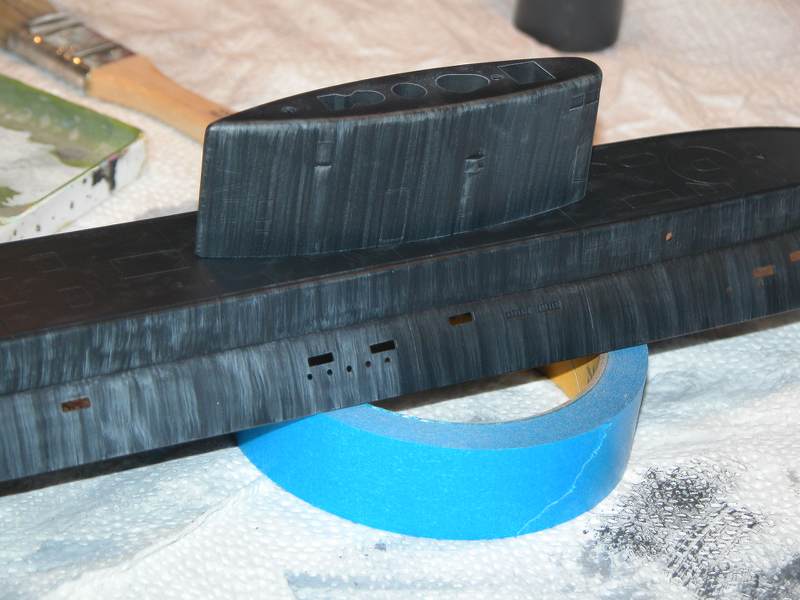
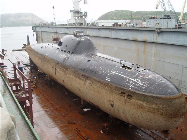
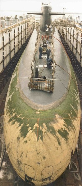
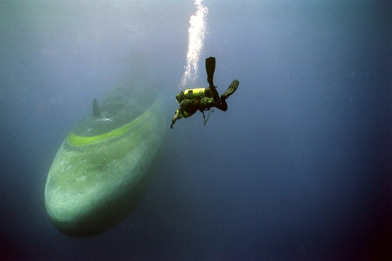
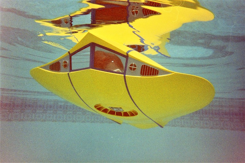
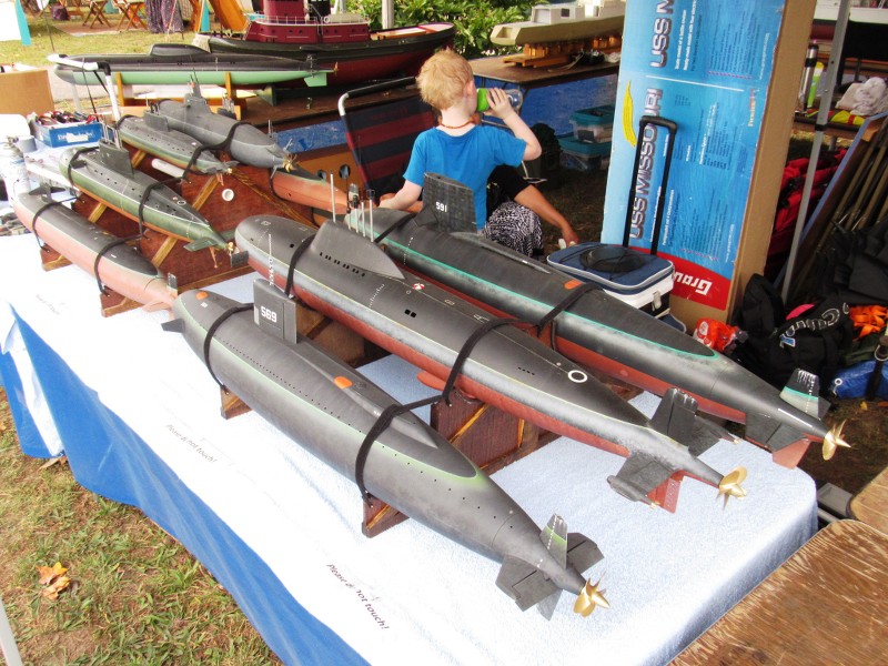
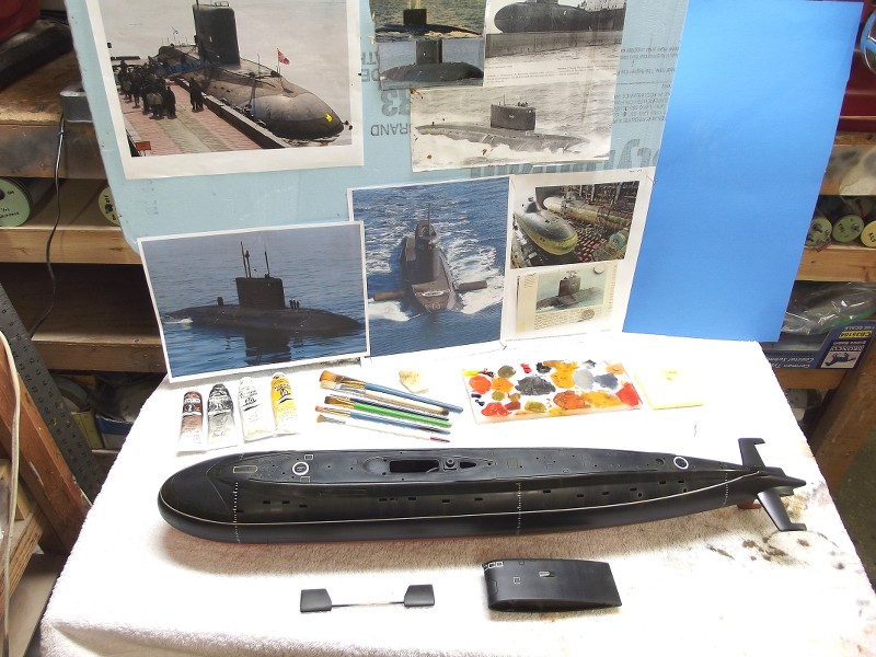
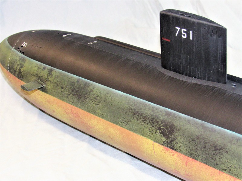
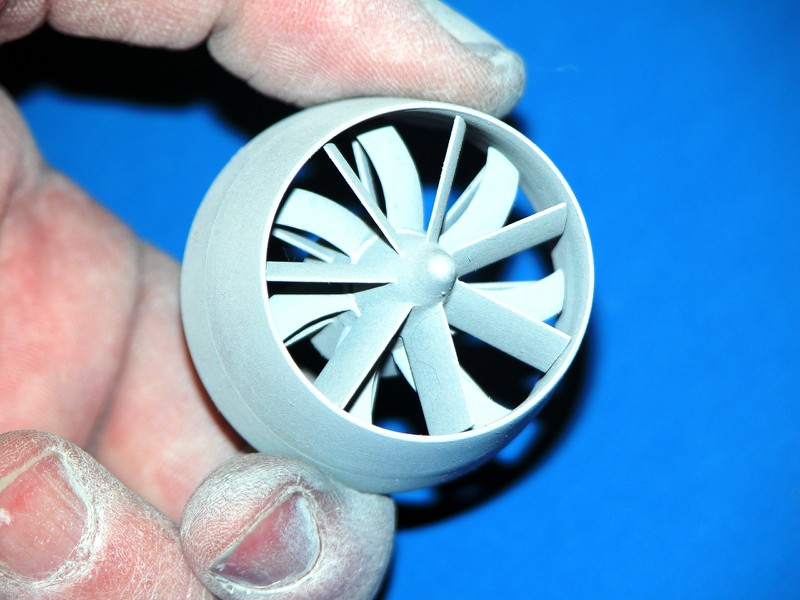
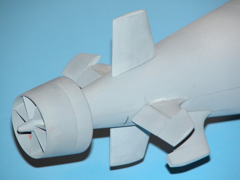
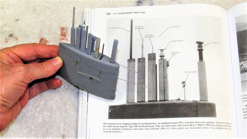
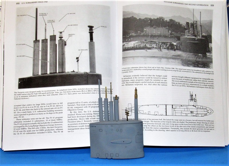
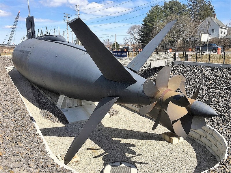
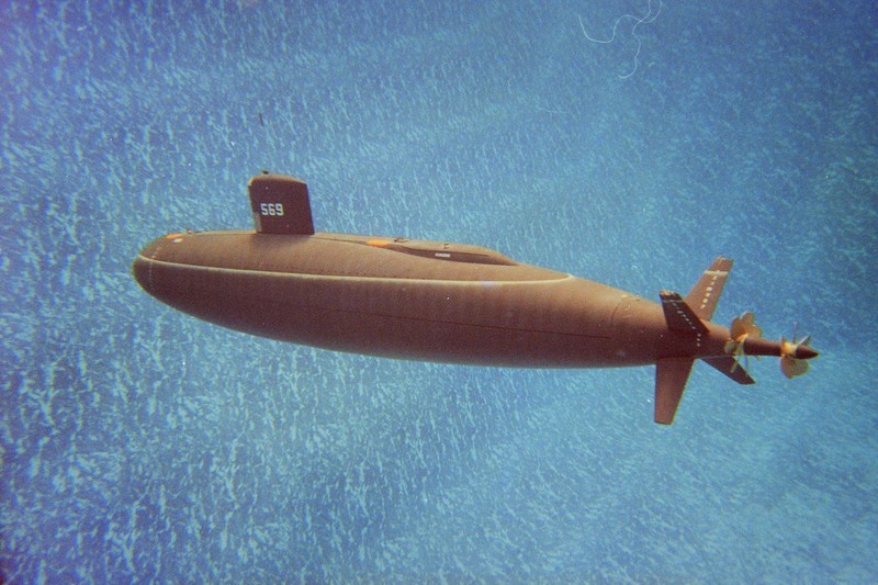
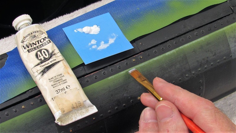
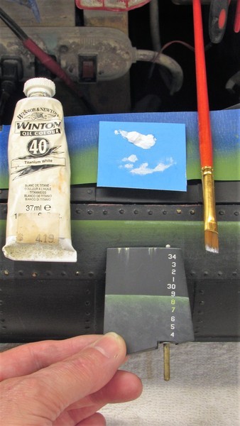
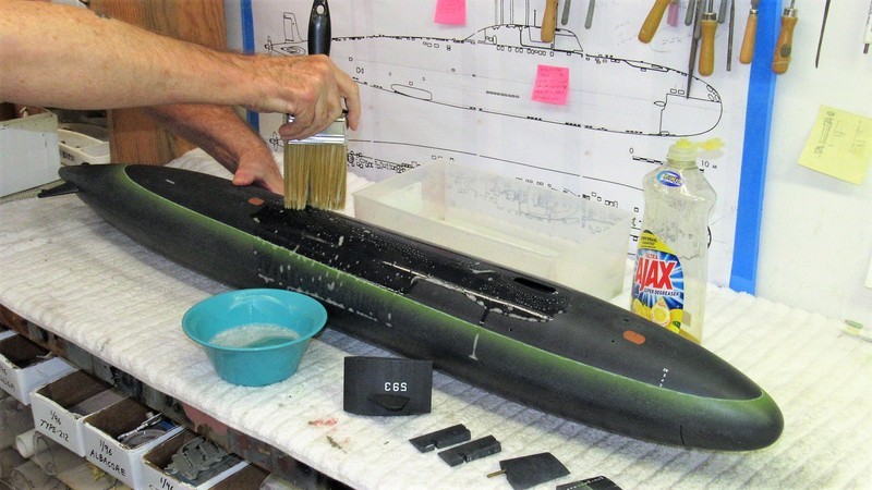
As someone once pointed out here, model submarines -- sleek, featureless post-war types anyway -- are, when compared with surface craft, rather boring simple cylinders with little structure variance or detail to please the eye. For that reason alone I do everything I can to make the most of what eye-catching elements there are to liven up the presentation. For modern submarines the eye-candy is almost always at the stern or what projects from atop the sail.
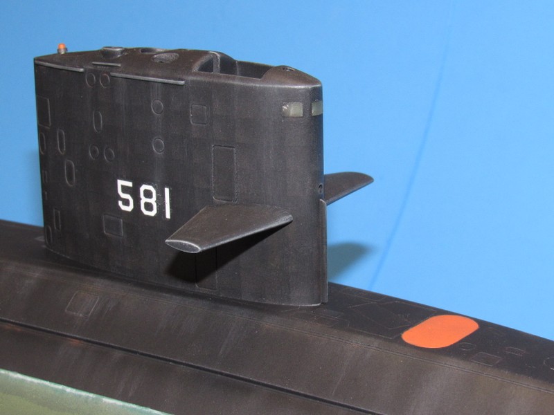
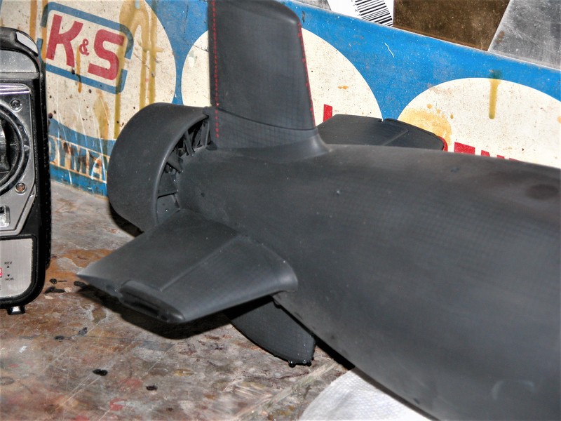
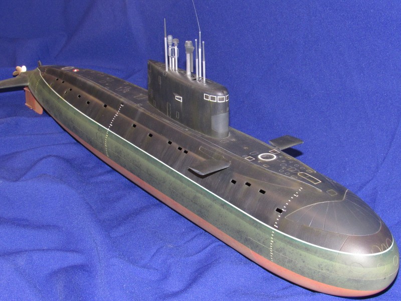
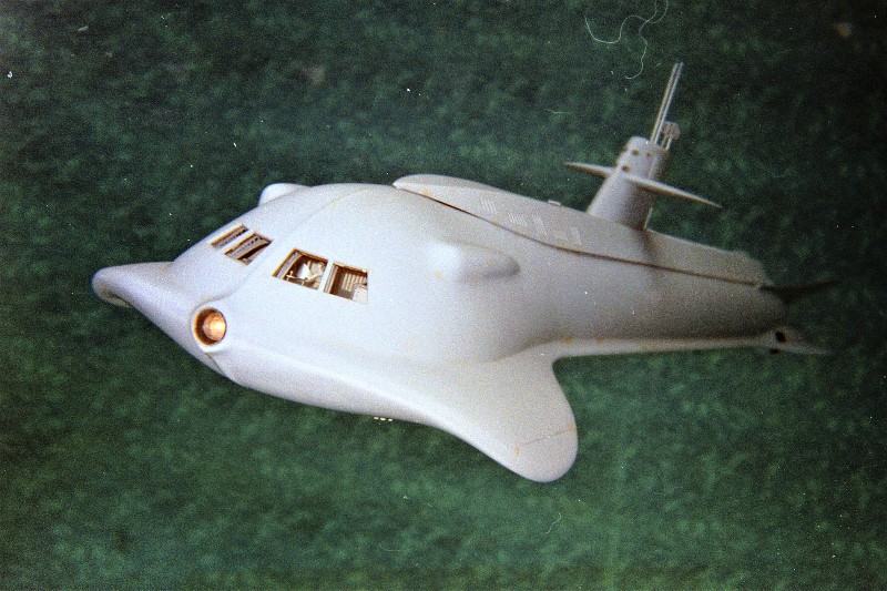
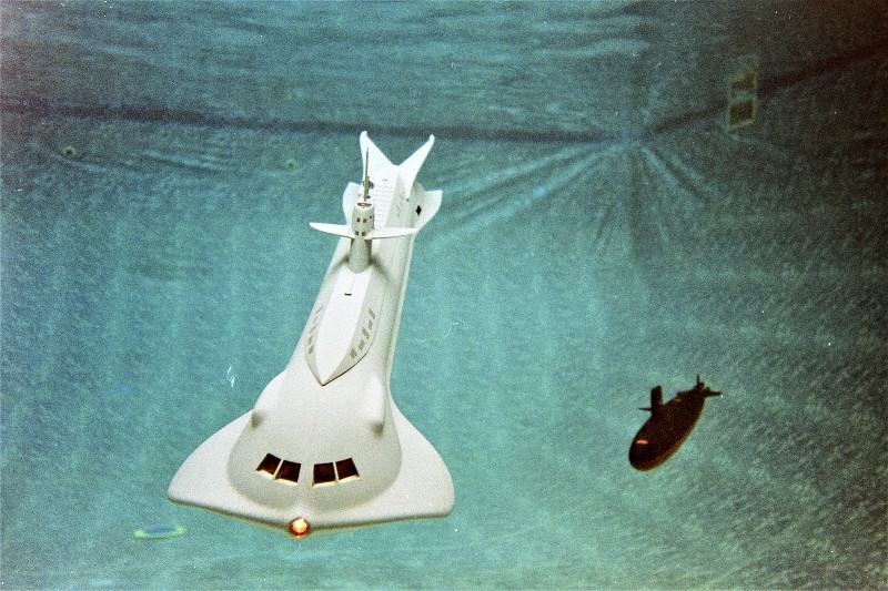
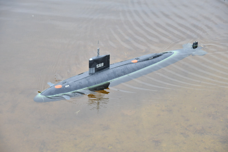
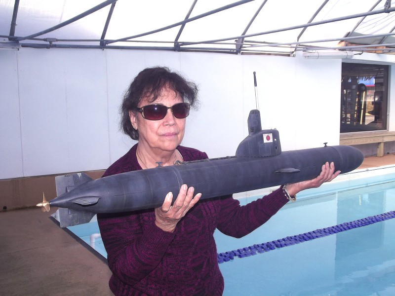
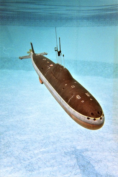
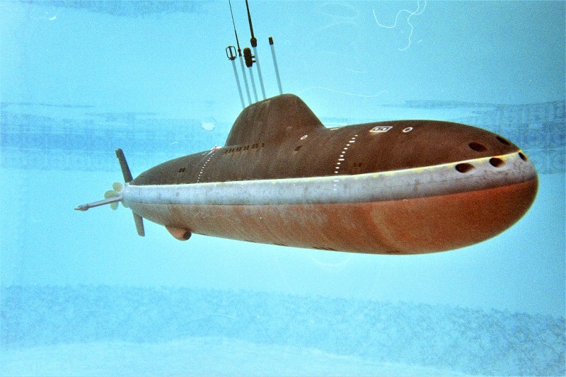
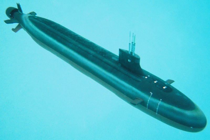
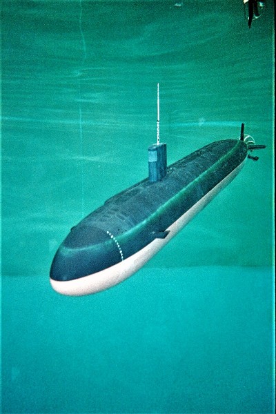
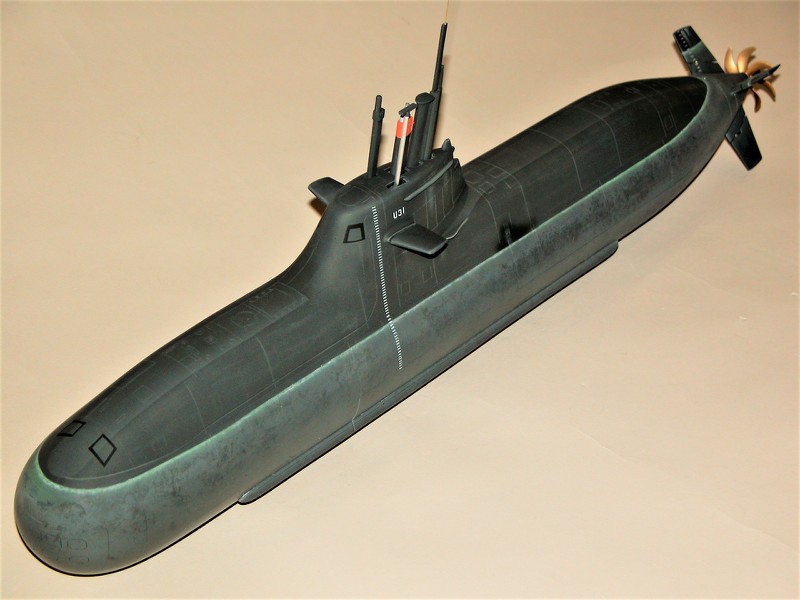
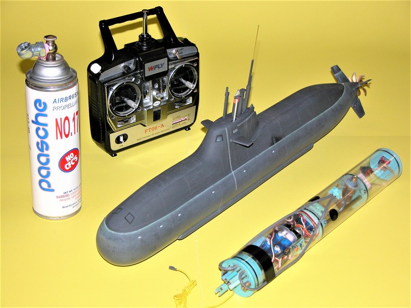
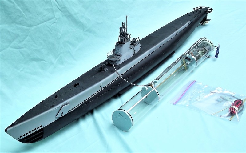
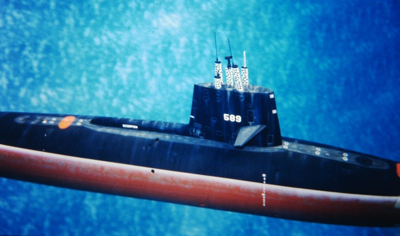
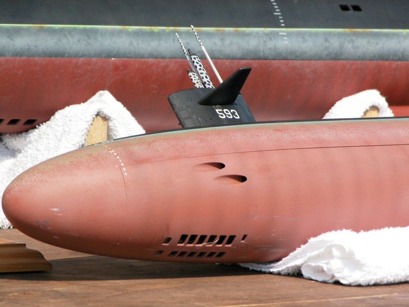
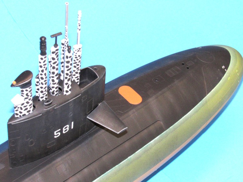
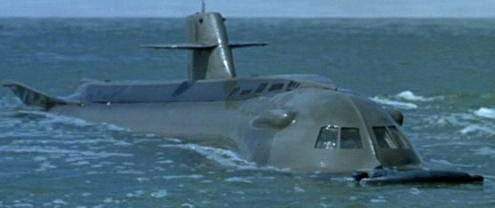
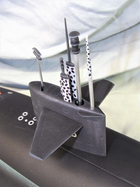
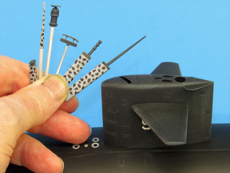
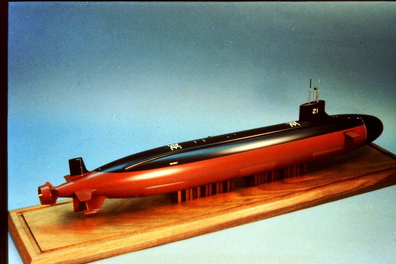
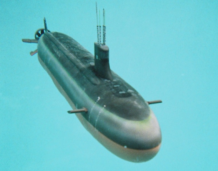
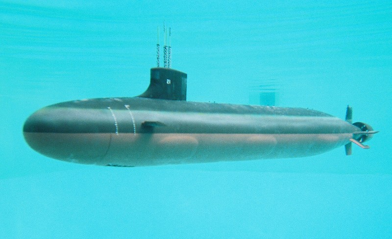
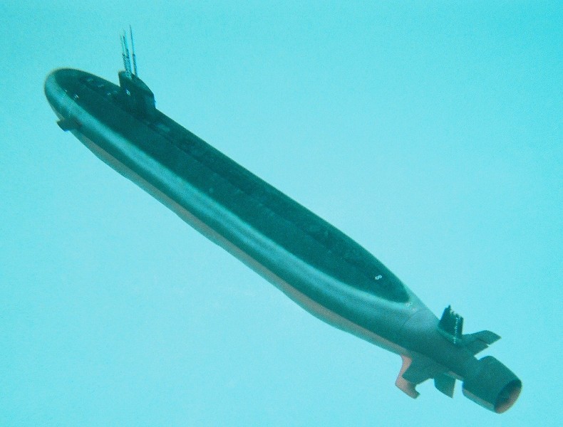
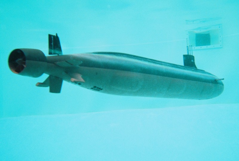
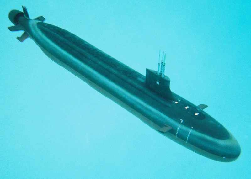
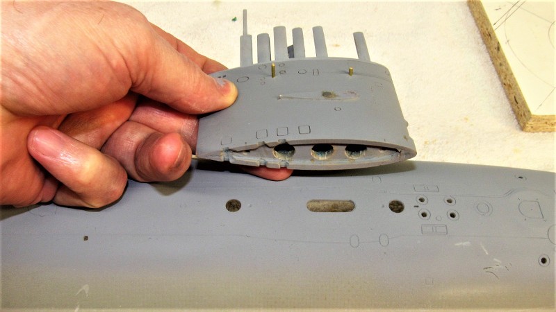
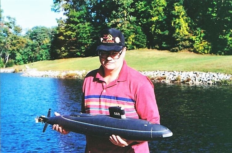
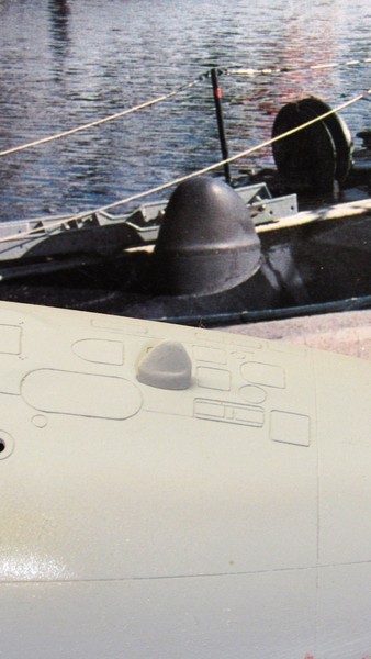
Nothing brings a sense of purpose or catches the eye better than the many retractable antennas and optical devices atop the submarines sail. These two illustrations of a Small World Model 1/96 BLUEBACK, with and without masts, makes my point.
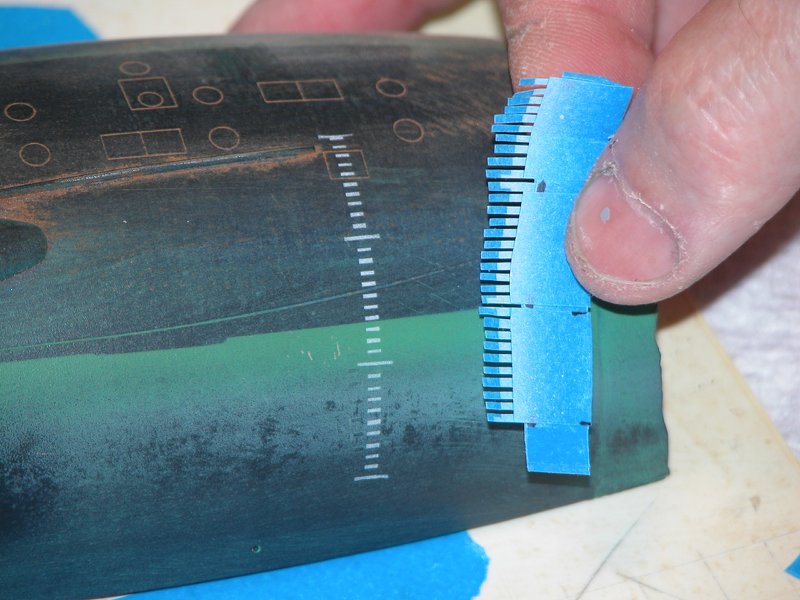
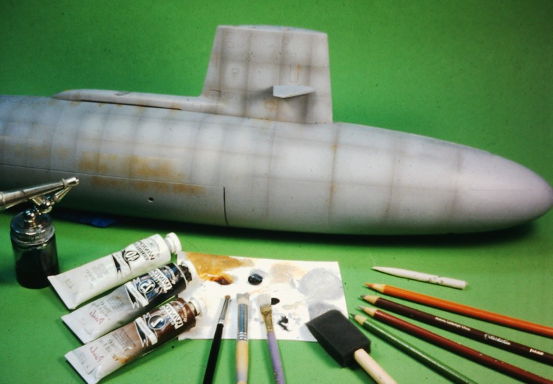
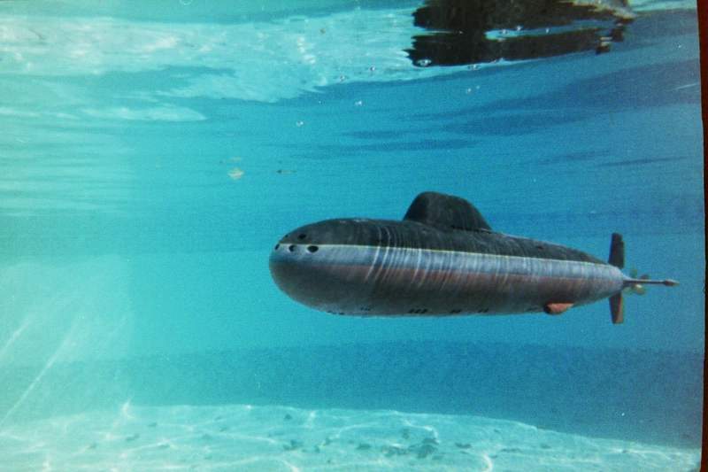
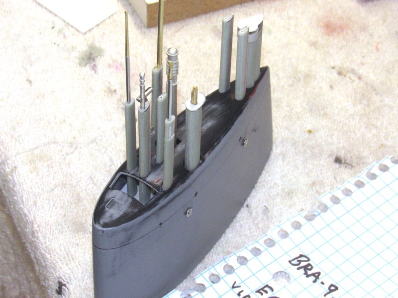
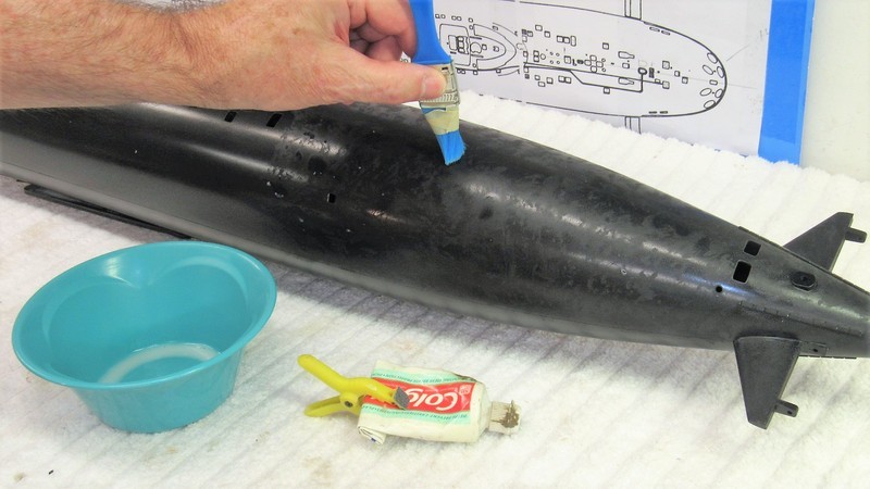
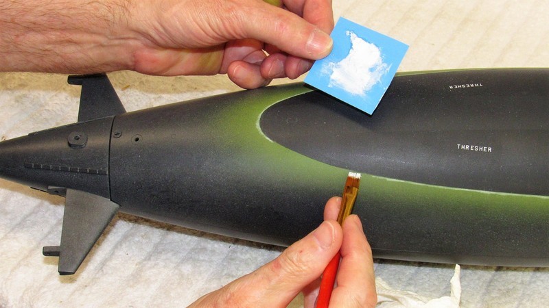
Sure, the model submarines sail can be jazzed up with oil-canning paint effects; dry-brushing to highlight edges and high-relief areas; and one can even provide practical dead-lights. But a big opportunity is lost if you don't also equip the display with extended fairings and scope cylinders.

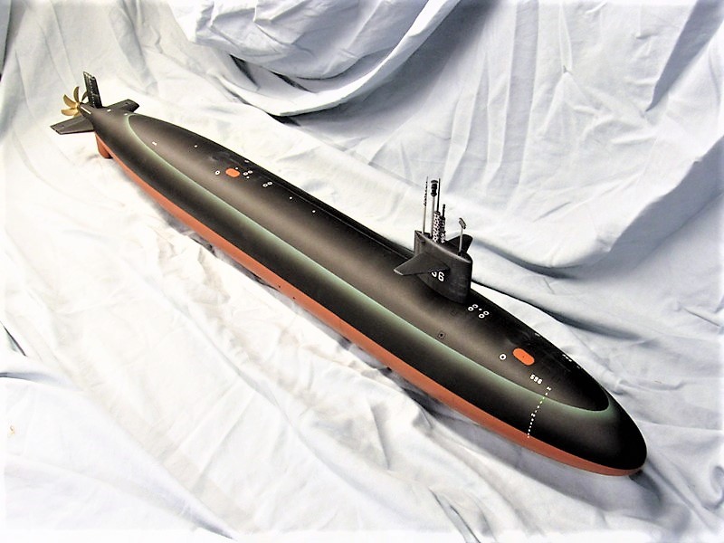
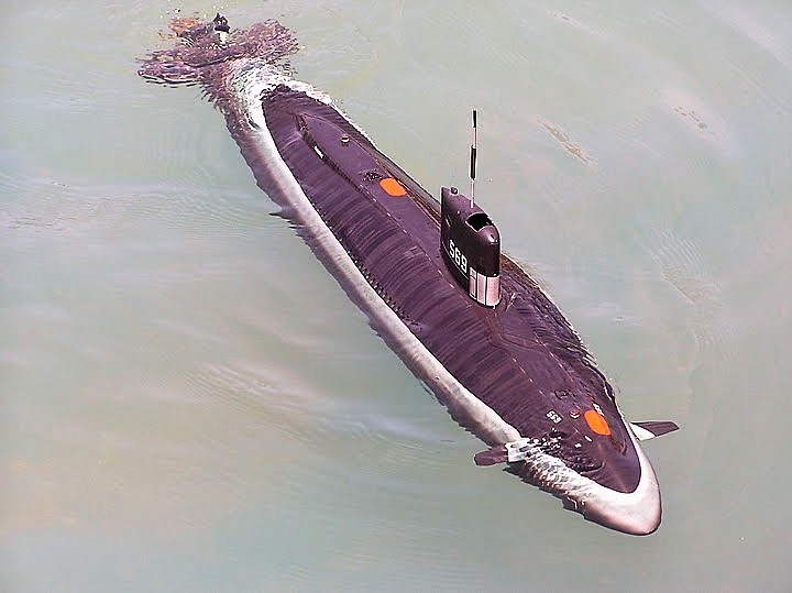
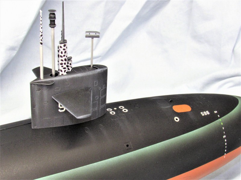
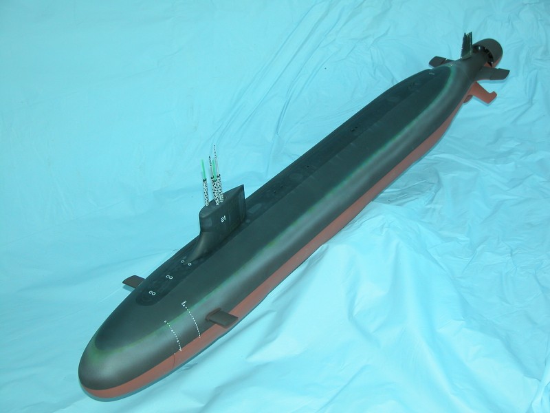
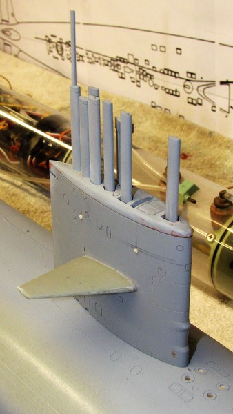
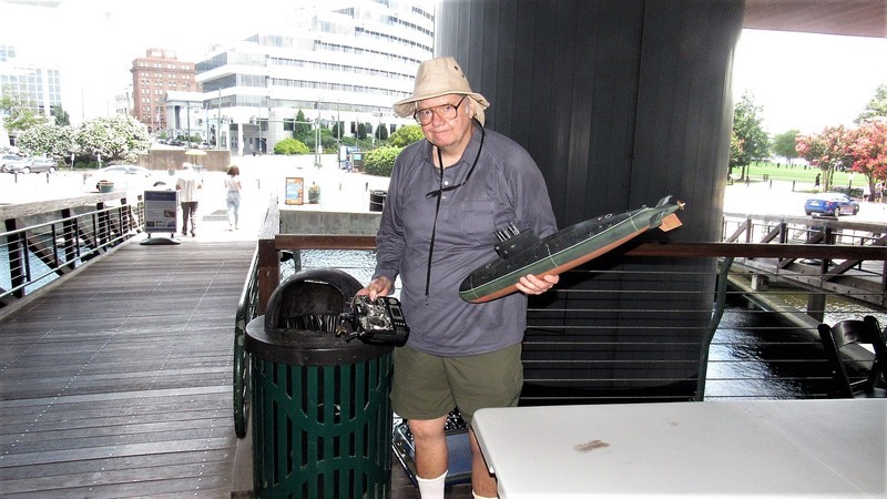
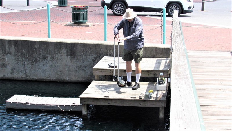
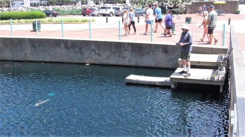
That same model submarine sail with the removable mast farings added -- and the antennas and optical devices atop them -- now becomes something worth looking at. Also, on a practical r/c submarine running near the surface, the feather produced by the masts is a vital visual aid needed by the driver to help him know just exactly where the submerged model is!
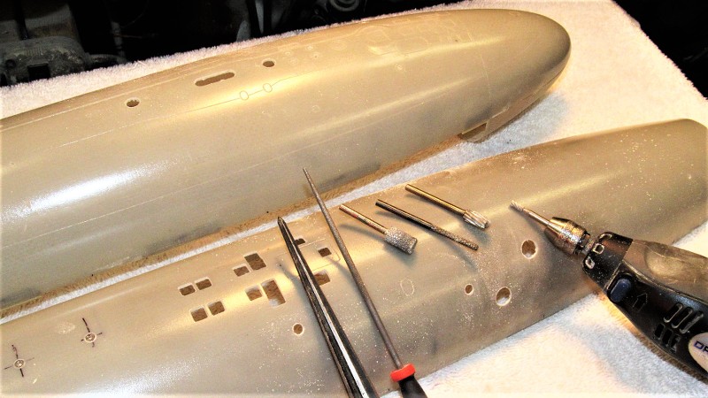
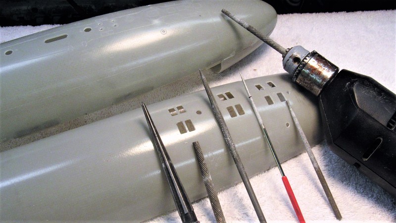
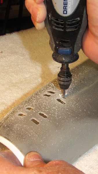
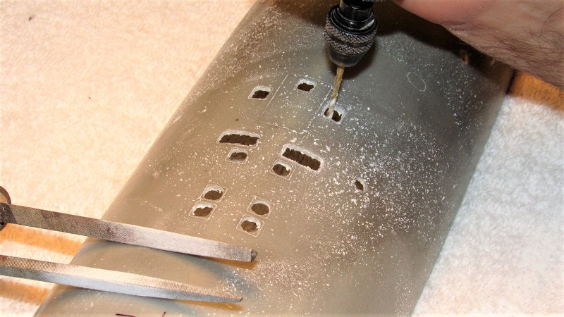
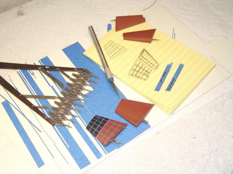
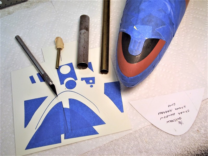
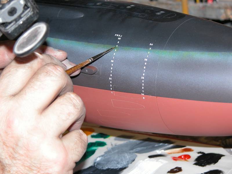
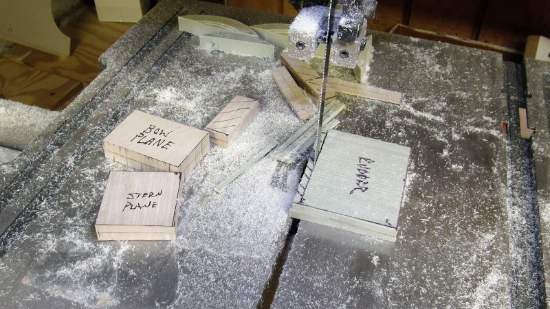
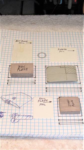
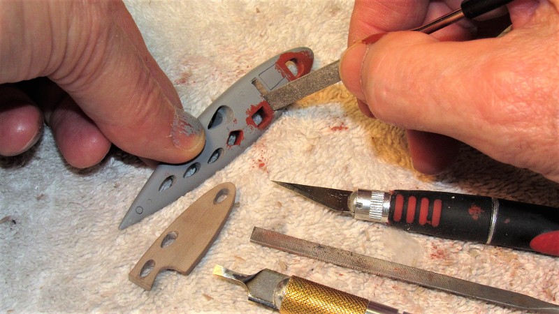
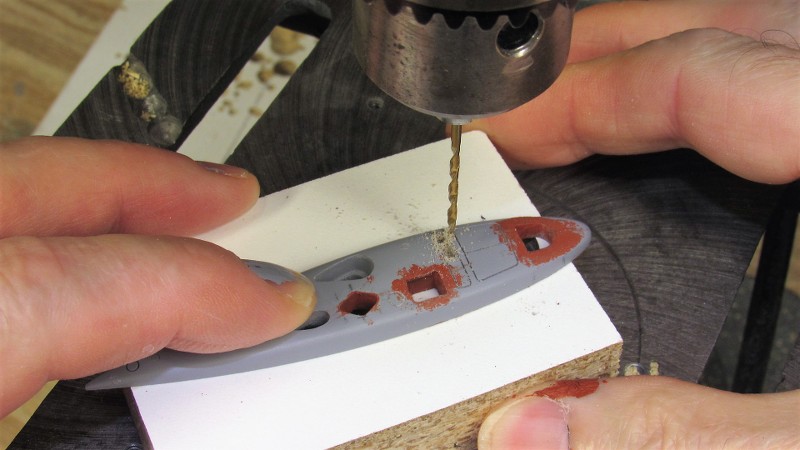
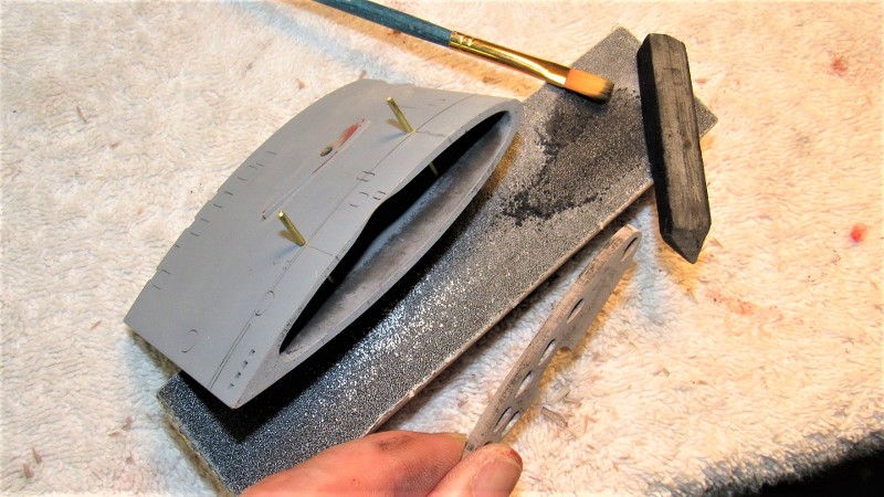
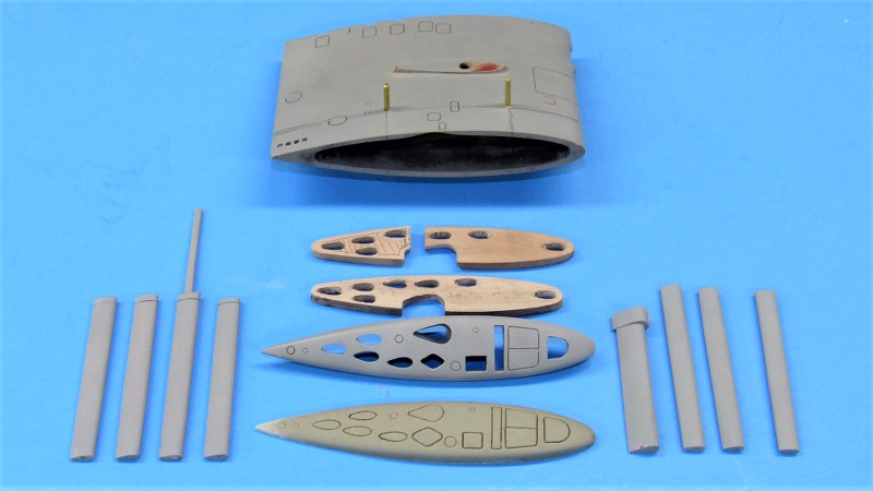
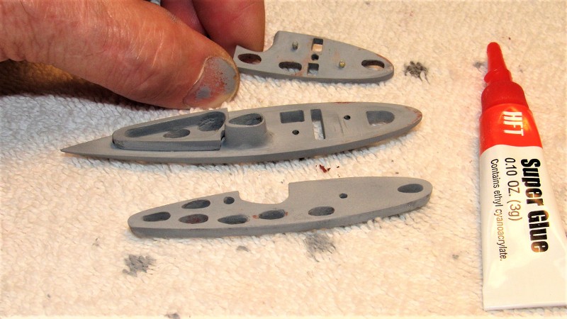
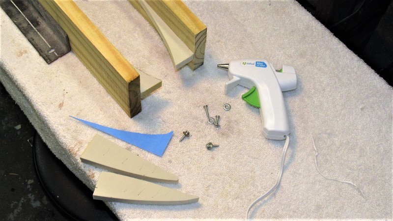
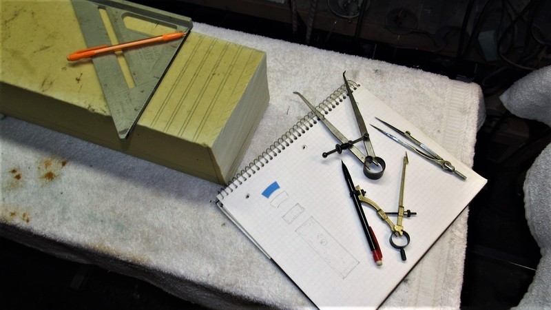
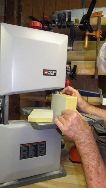
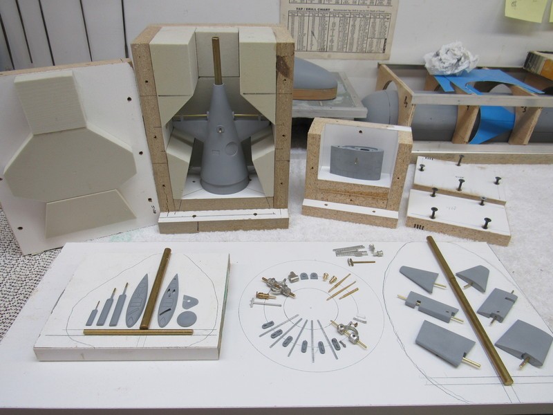
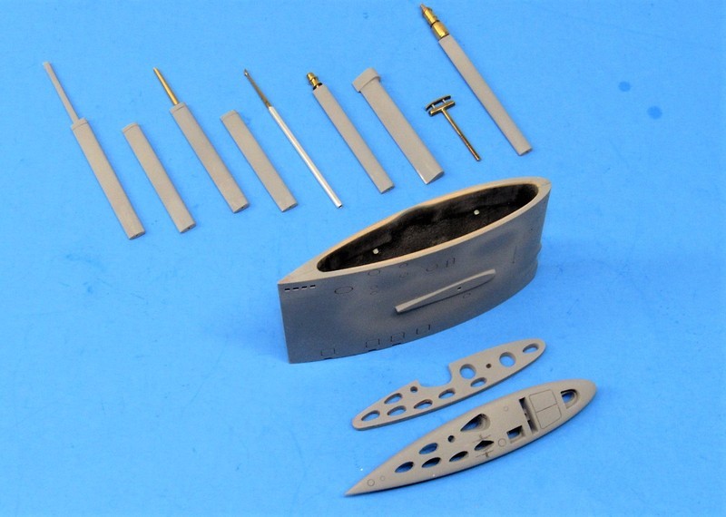
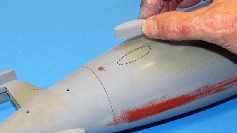
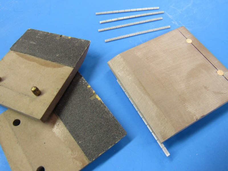
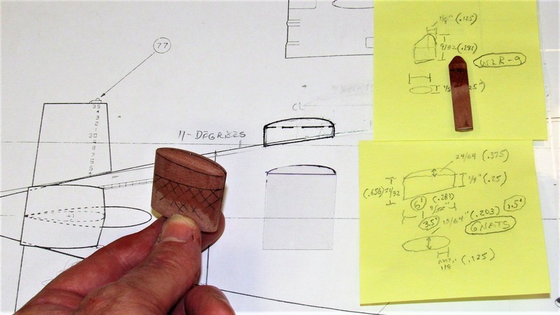
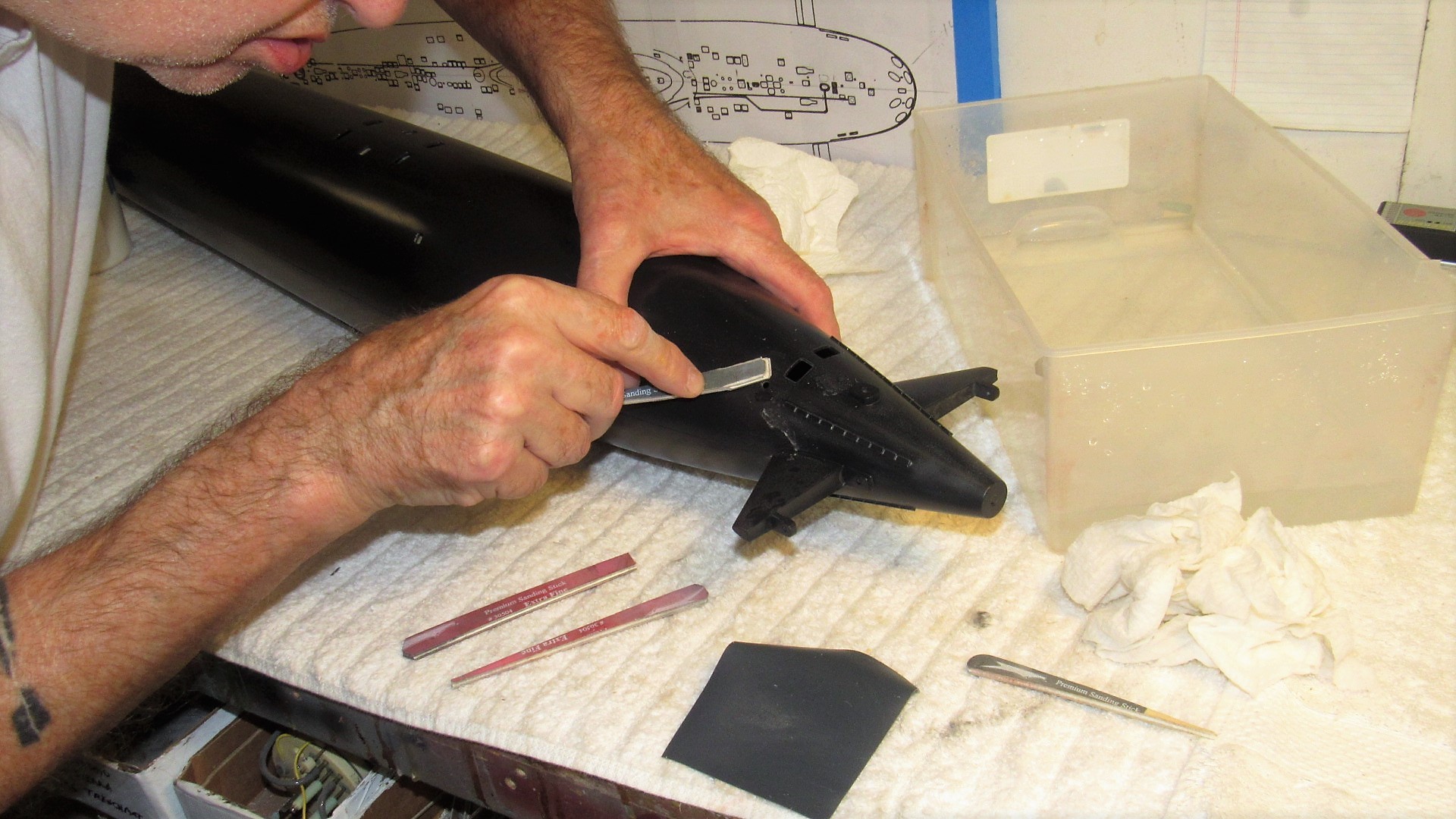
Getting back to the 1/96 STURGEON kit. The sail masters: two sail planes; the sail proper; and two alternate sail tops. One sail top with scribed outlines representing the flush fitting tops of the mast fairings, and the other sail top provided with tear-drop shaped holes that would pass mast farings represented in the 'raised' position.
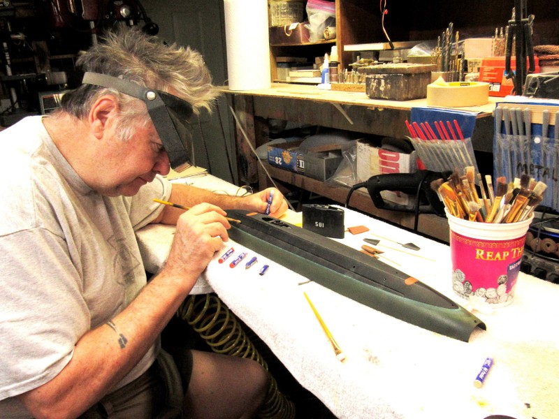
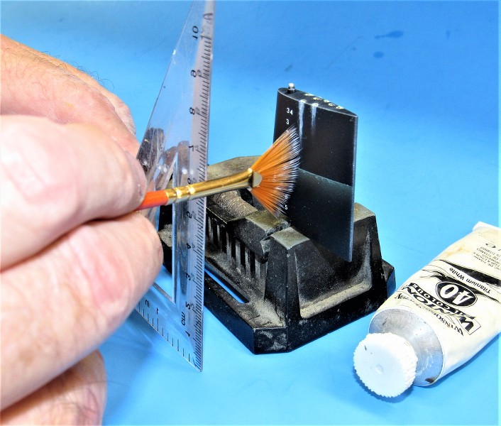
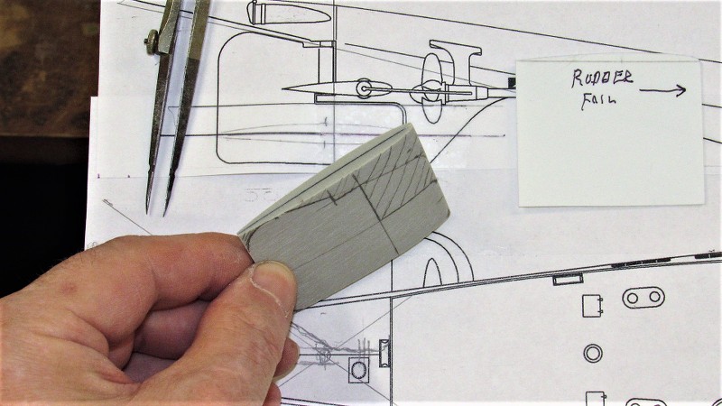
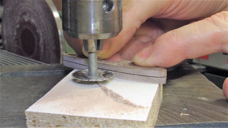
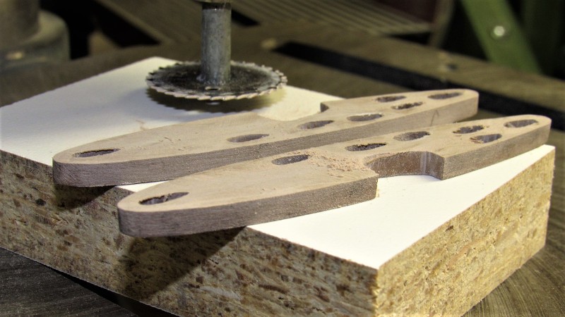
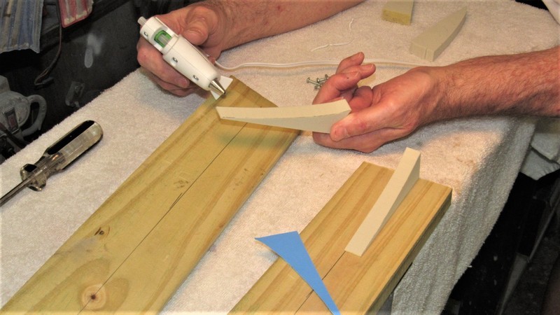
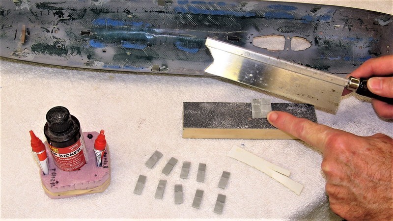
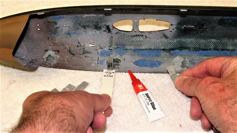
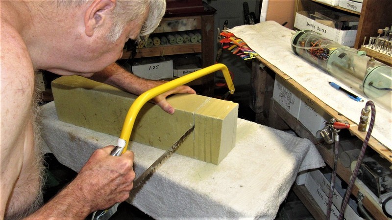
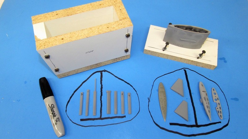
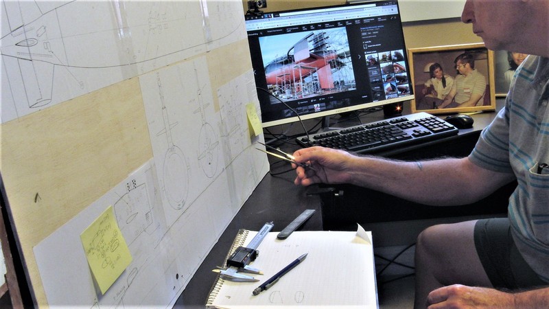
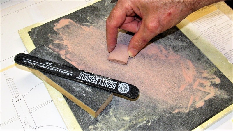
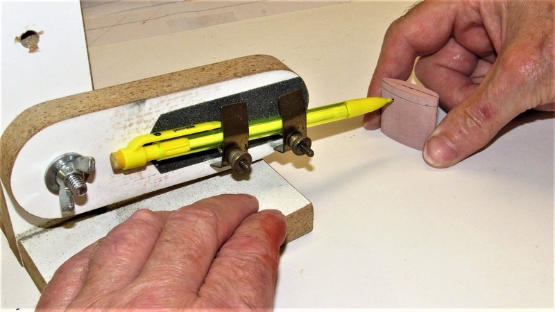
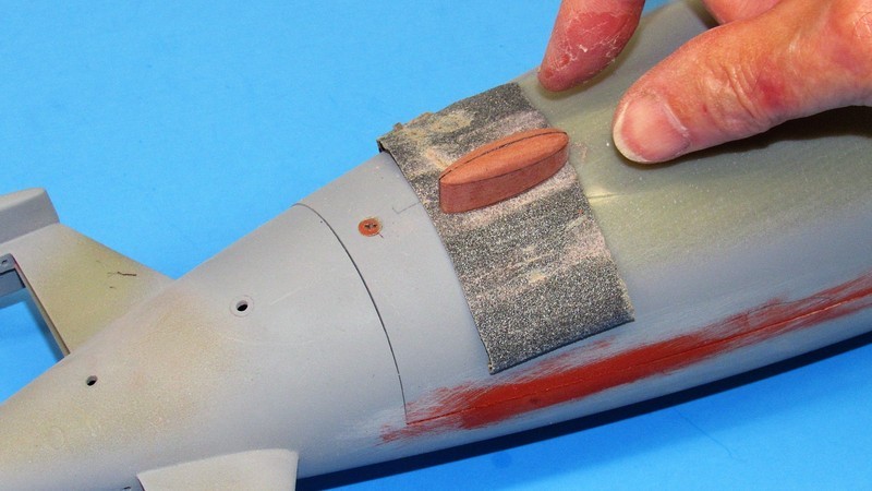
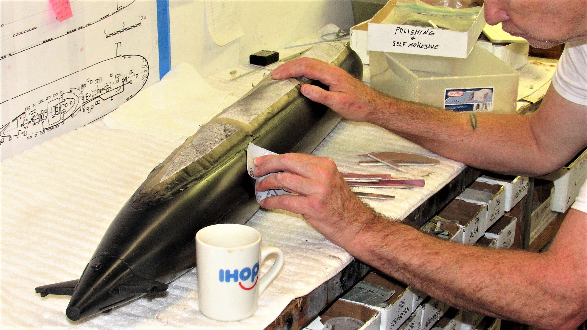
I give the eventual kit-assembler a choice: either represent the model with retracted masts, or raised masts. Here I'm giving final shape with a hand-vice to fairing blanks. Using a sanding block to get them to proper cross-section and thickness
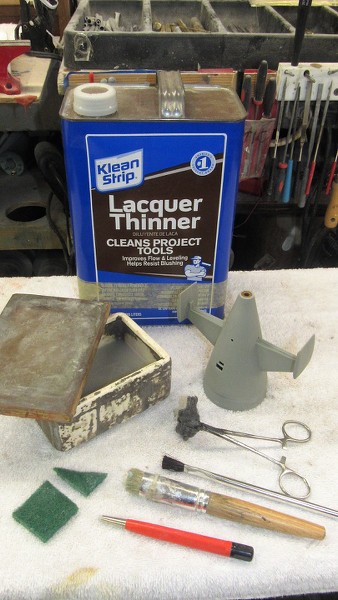
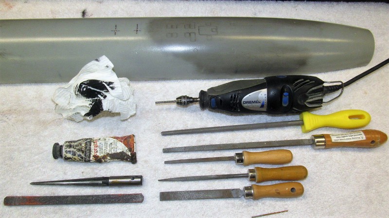
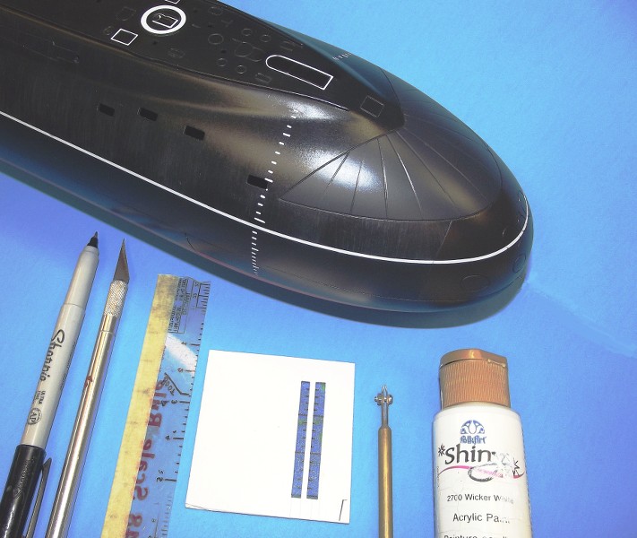
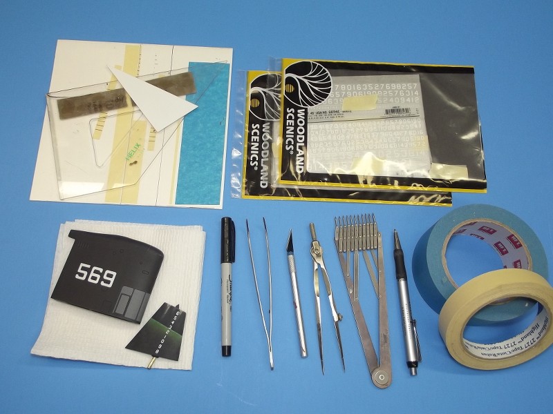
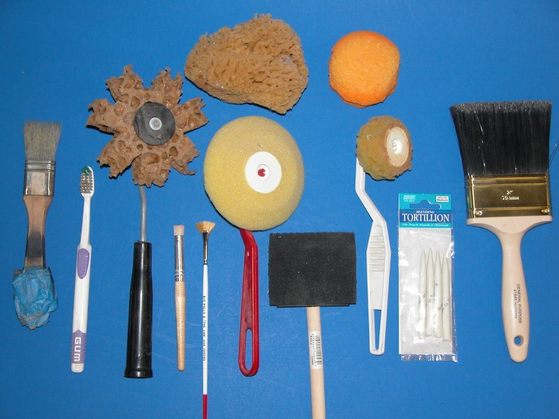
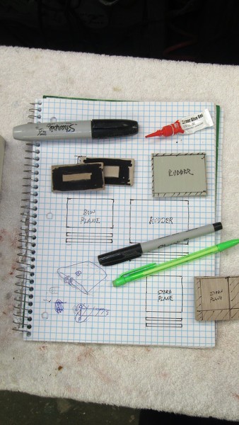
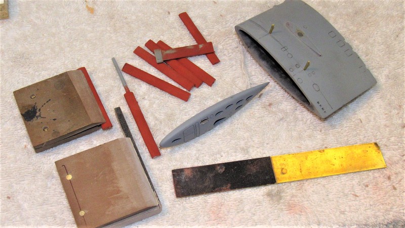
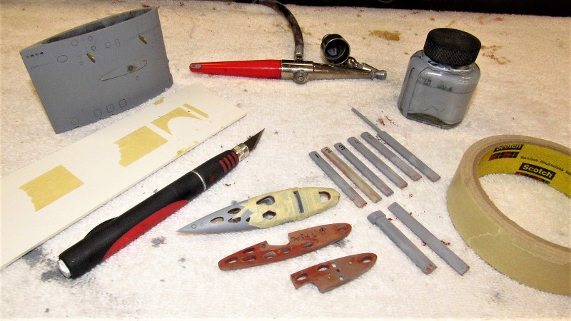
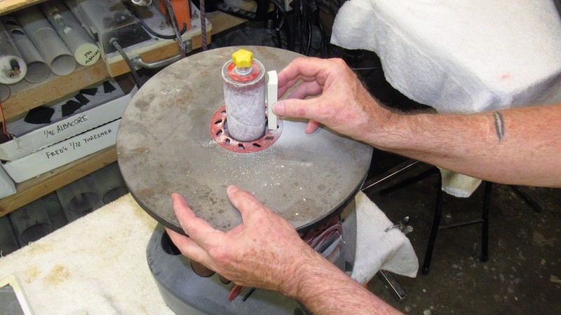
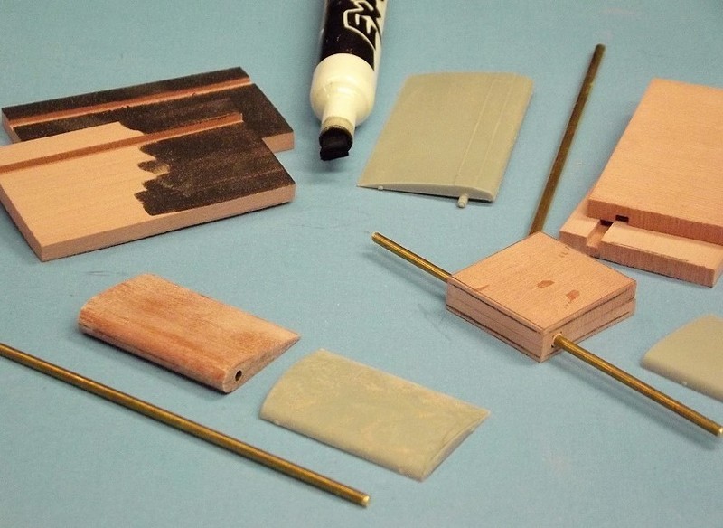
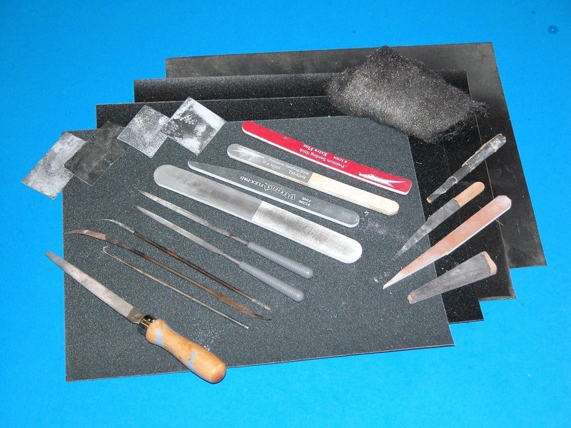
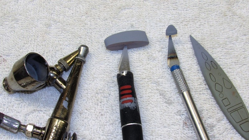
Exacting model-building often required close-in hand-work -- the work firmly held in some kind of hand-vice at eye-level as you work it with the other hand. A jeweler's hand-vice takes many forms, the plastic wedge type above; beneath that a more traditional screw clamping type; and below the more familiar collet types used to hold the cylindrical shank ends of work so equipped.
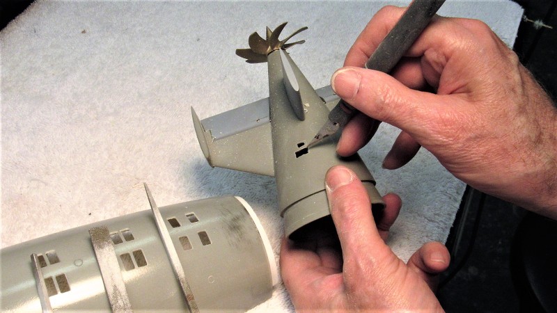
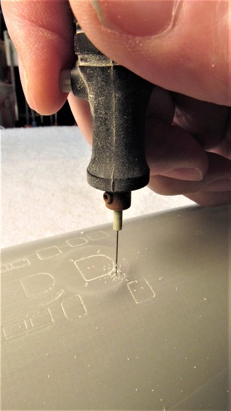
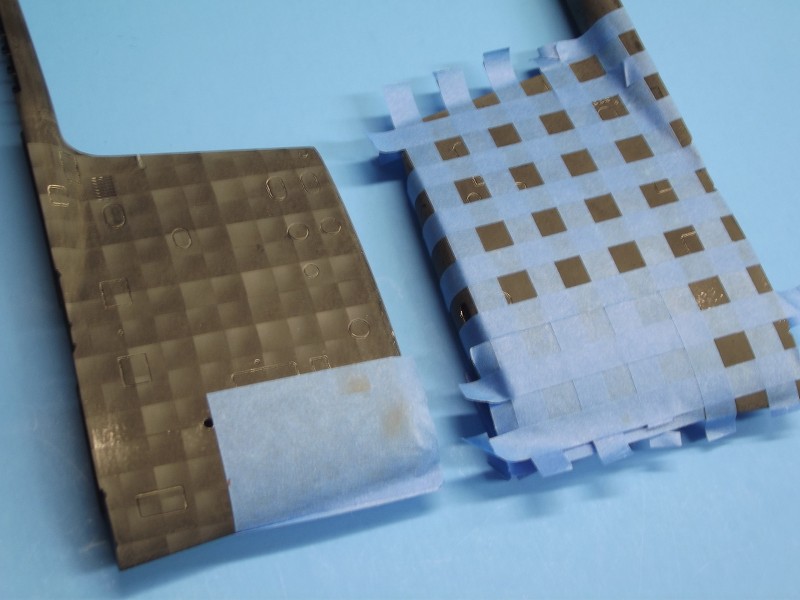
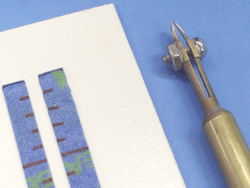
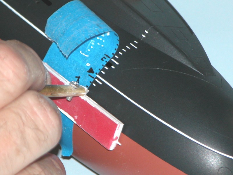
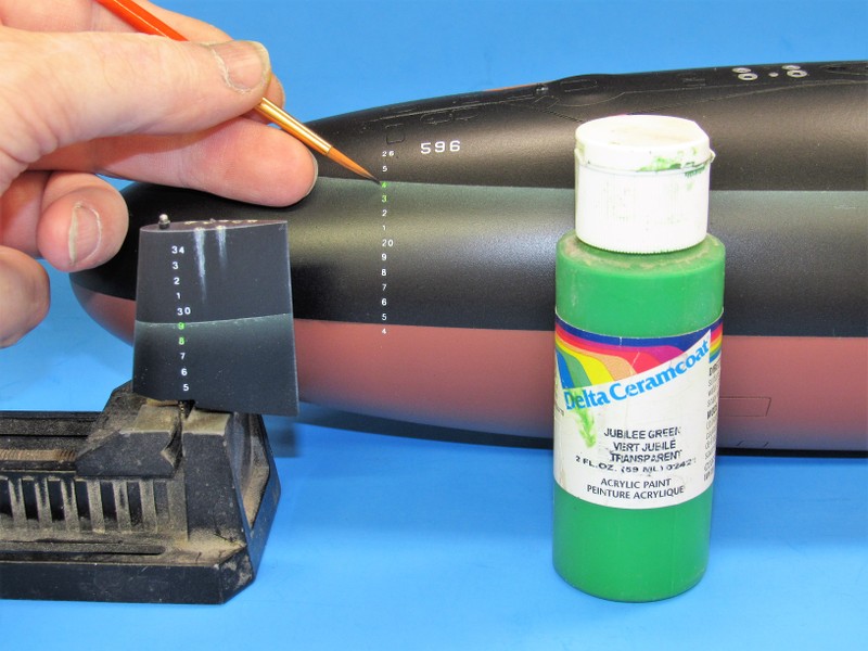
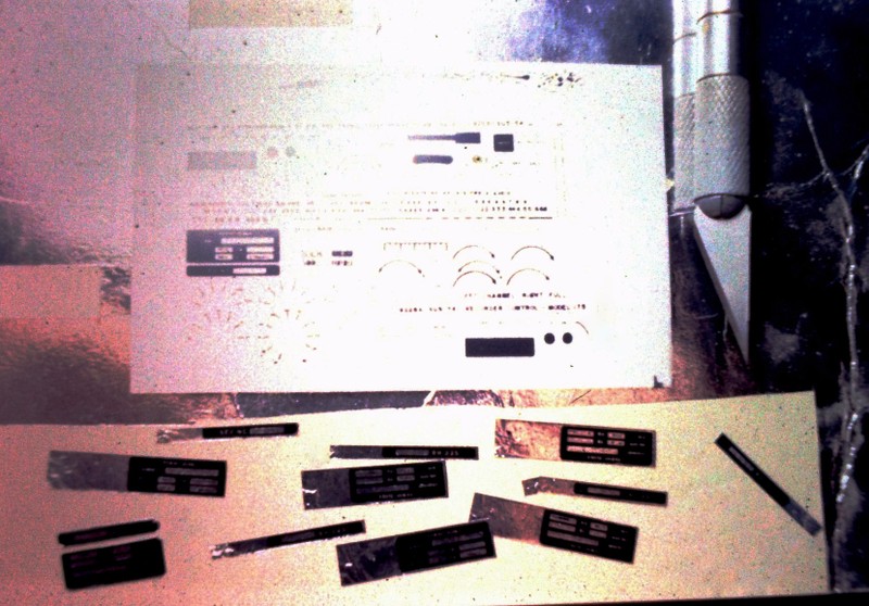
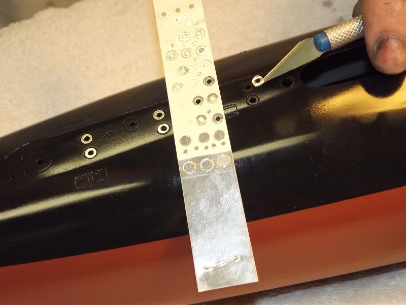
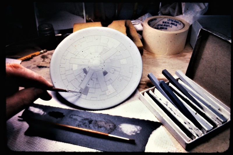
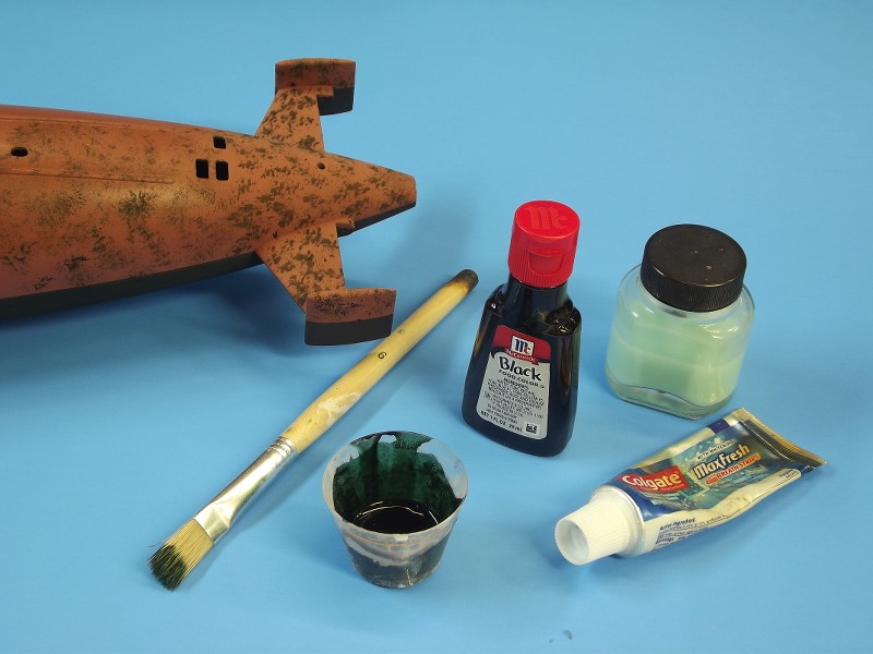
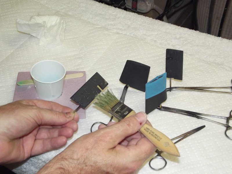
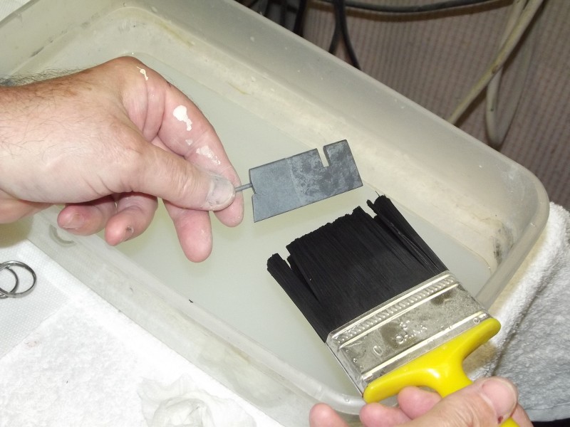
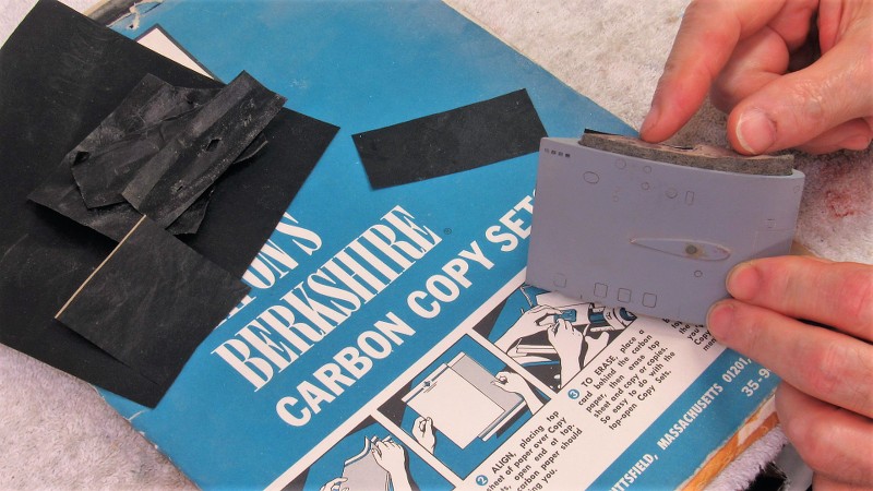
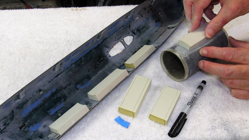
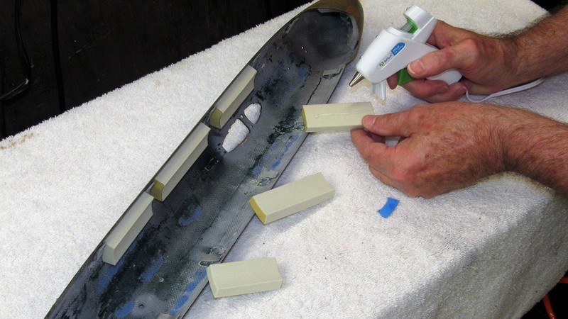
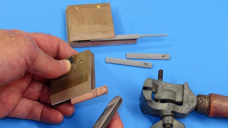
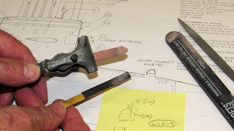
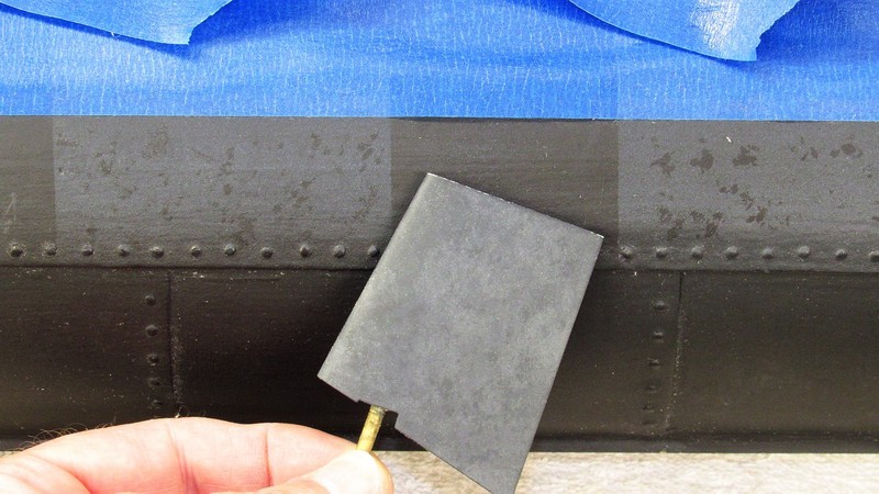
I make these simple clamp type hand-vices for fragile work that would otherwise bend and break if not supported longitudinally -- such as these highly detailed rows of zincs being carefully engraved and sanded with the aid of this gripping tool. Note that the faces of the two clamp halves have glued to them sandpaper. It's there to assure a no-slip grip to the work. This hand-vice works through the pressure applied with finger and thumb, giving absolute control over clamping pressure.
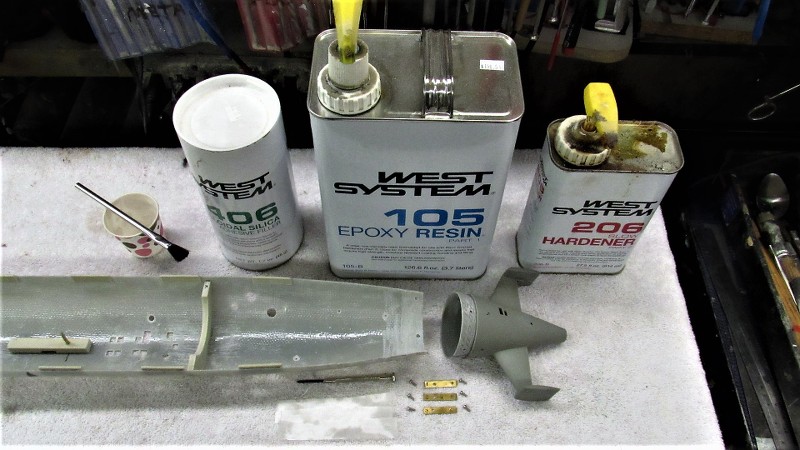
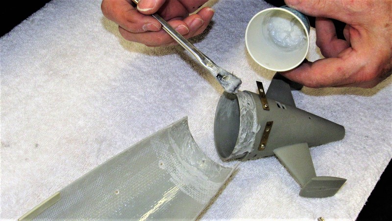
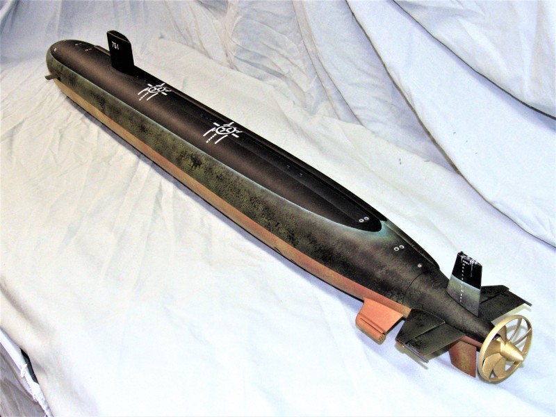
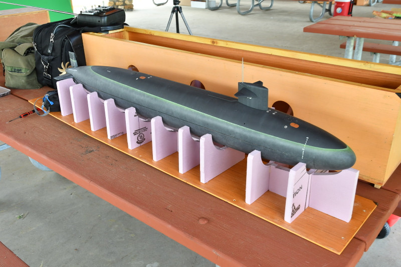
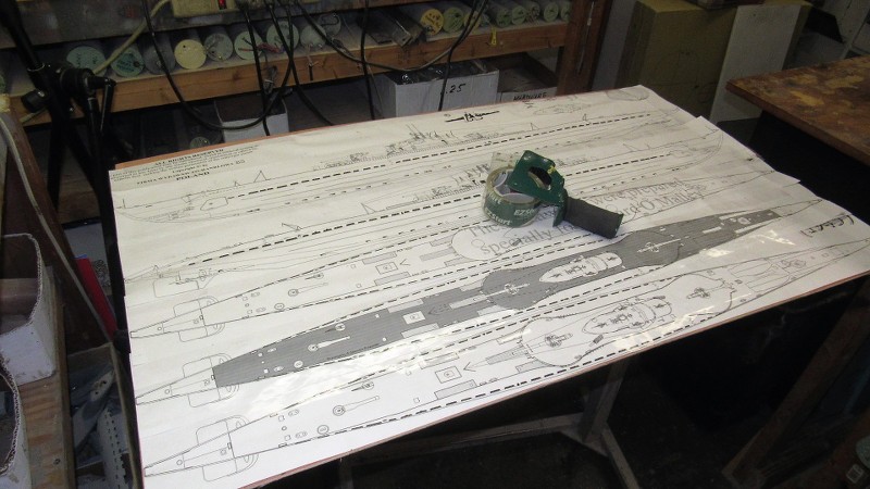
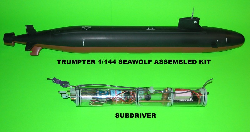
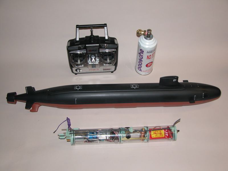
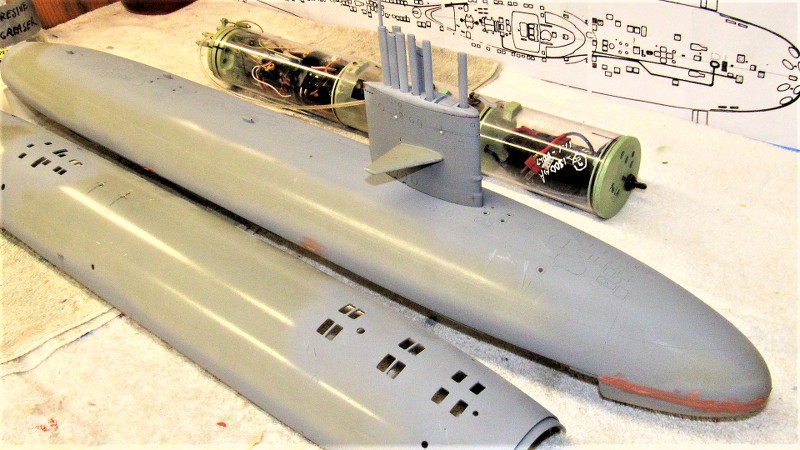
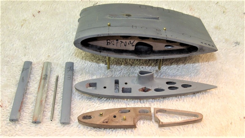
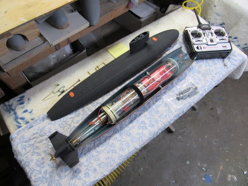
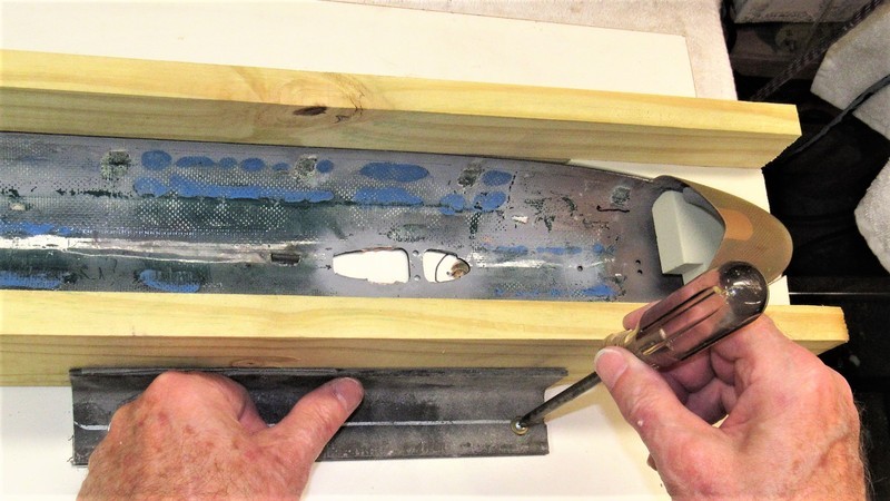
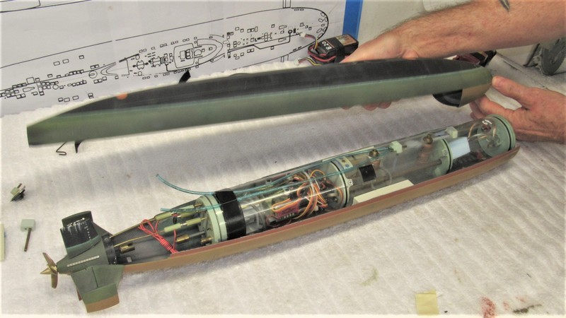
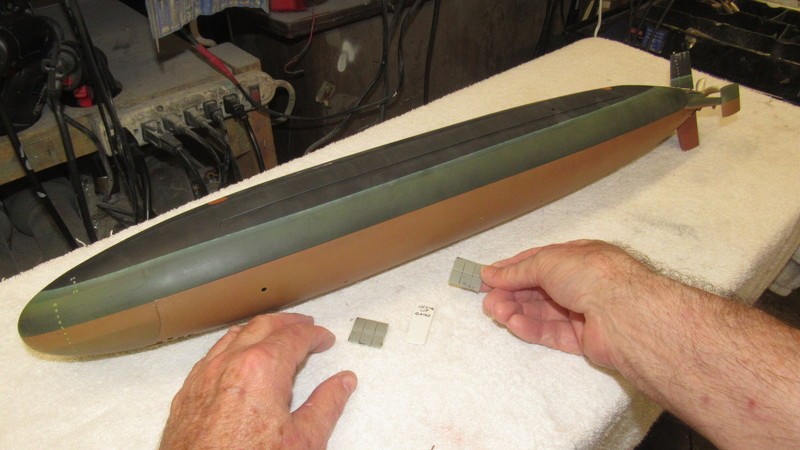
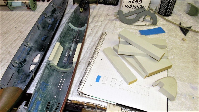
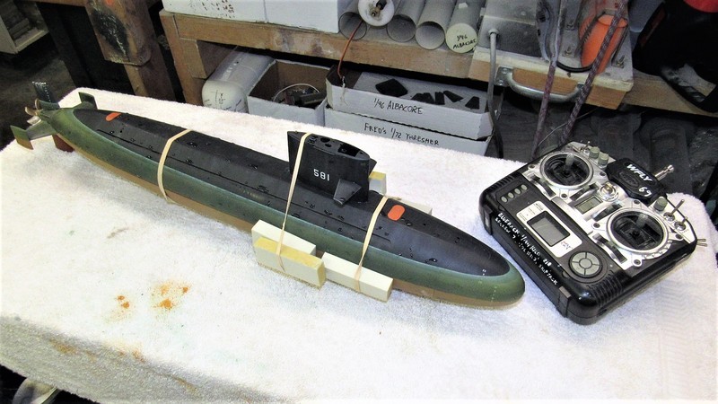
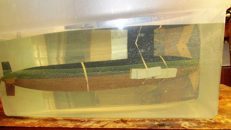
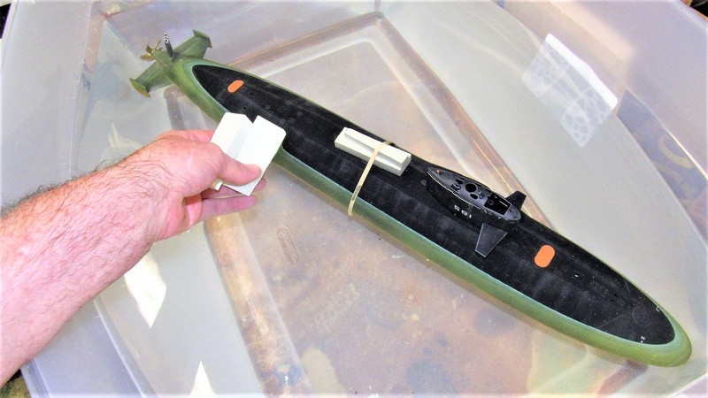
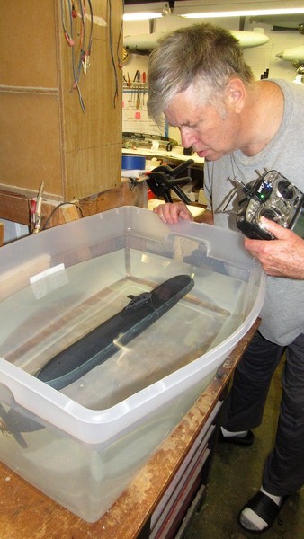
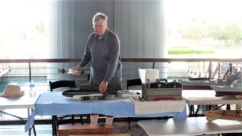
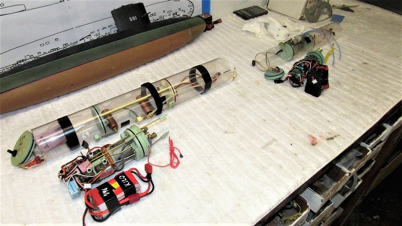
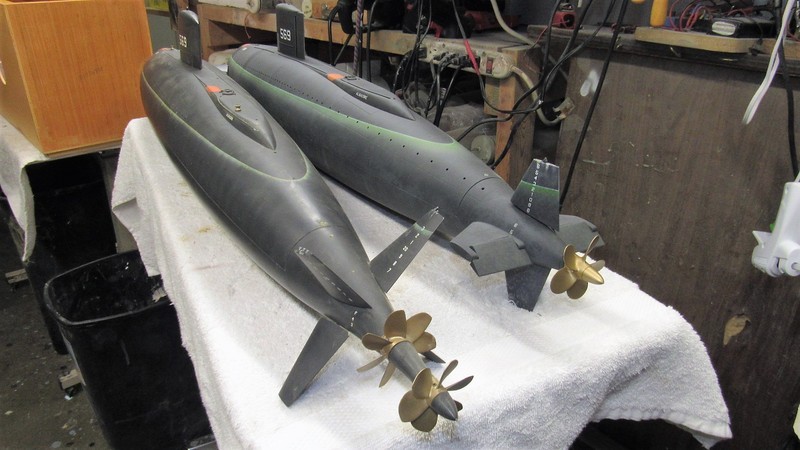
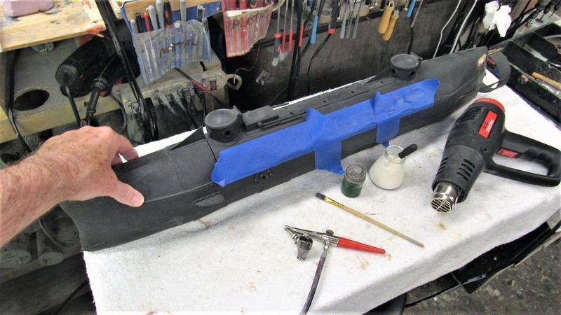
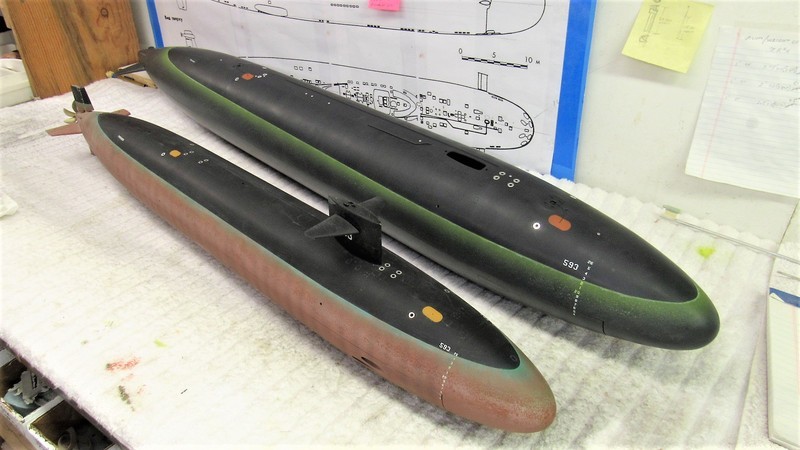
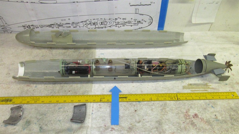
Paralleling the work of making the masters and tools for eventual 1/96 STURGEON kit production is the assembly of a working model. Not only for my personal enjoyment, but primarily serving as a validation article to insure that all kit fit and function problems are identified and solved before committing the masters to tool making. I don't want to unleash a flawed kit on an unsuspecting public -- that would be bad ju-ju!
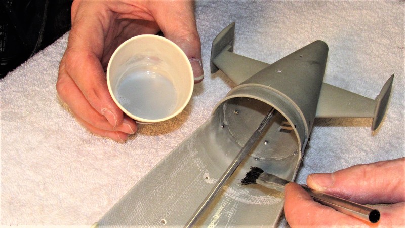
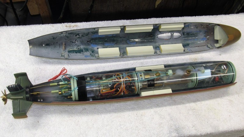
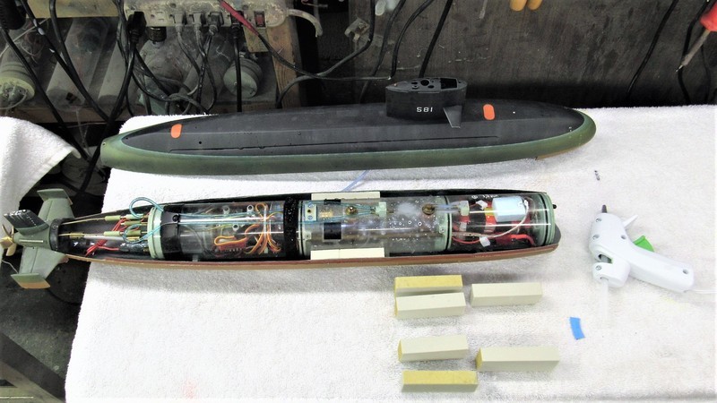
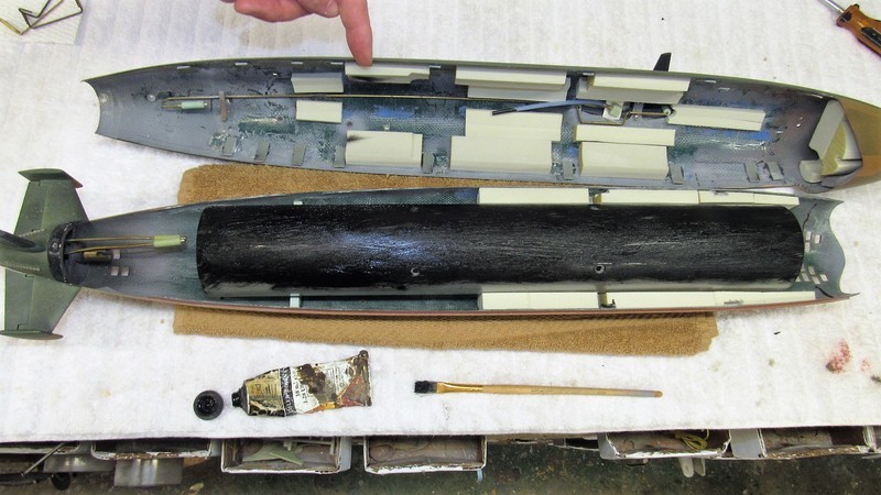
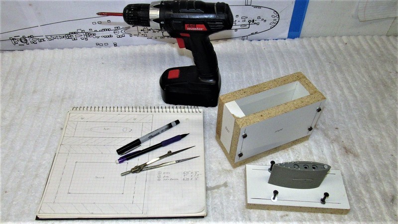
Three things I get straight before construction begins is to place the center of gravity (center of mass) at the longitudinal center of the hull; position the SubDriver (SD) so the center of the ballast tank is where the assembled models c.g. will be; and place the c.g. as low in the hull as possible to insure adequate static roll stability.
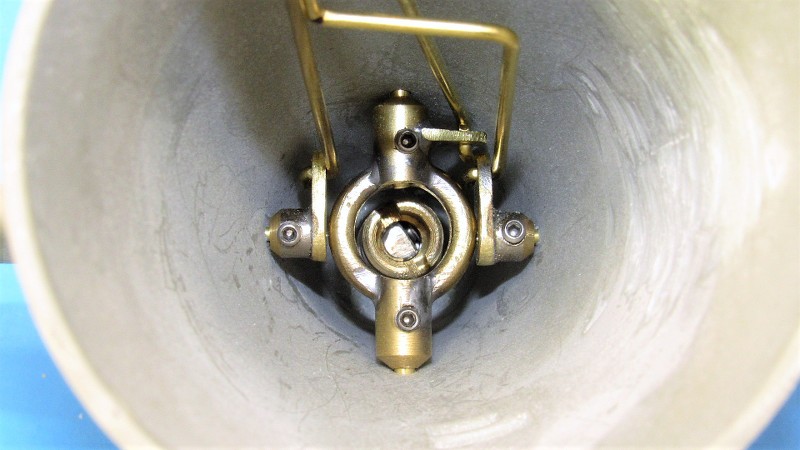
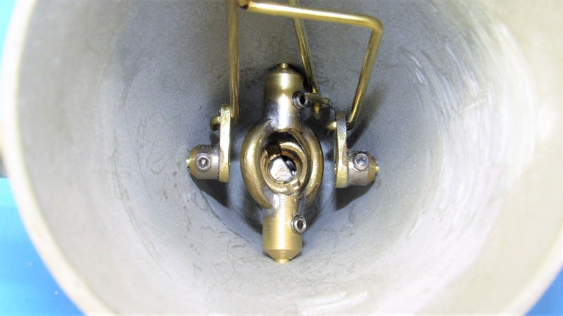
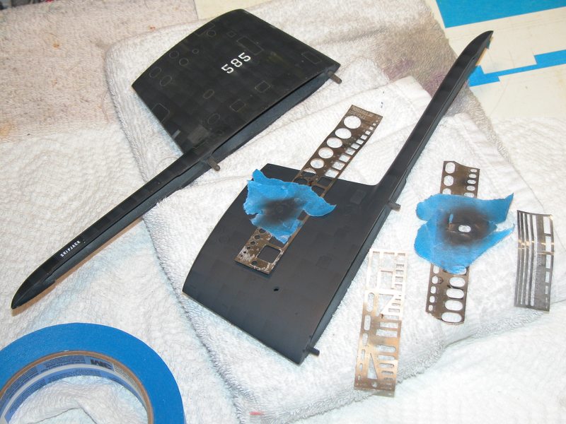
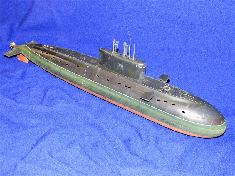
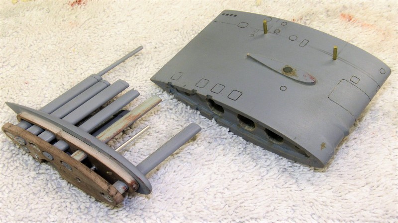
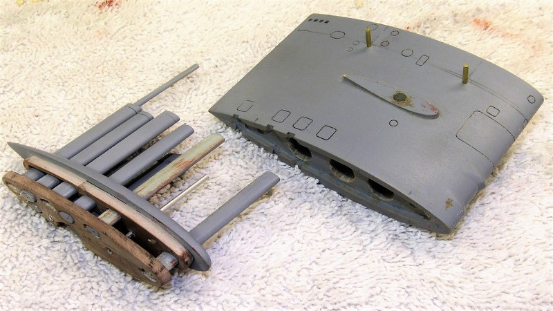
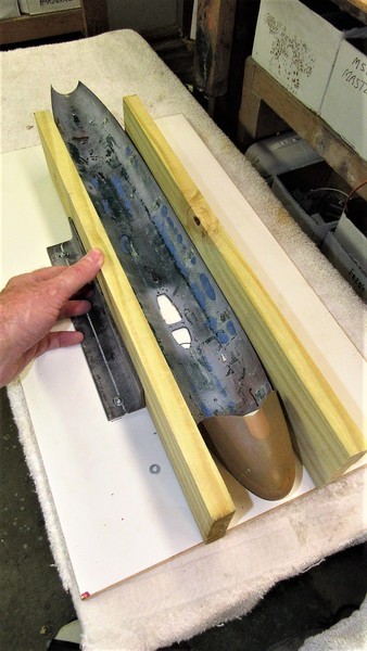
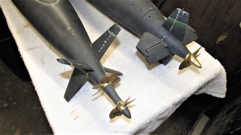
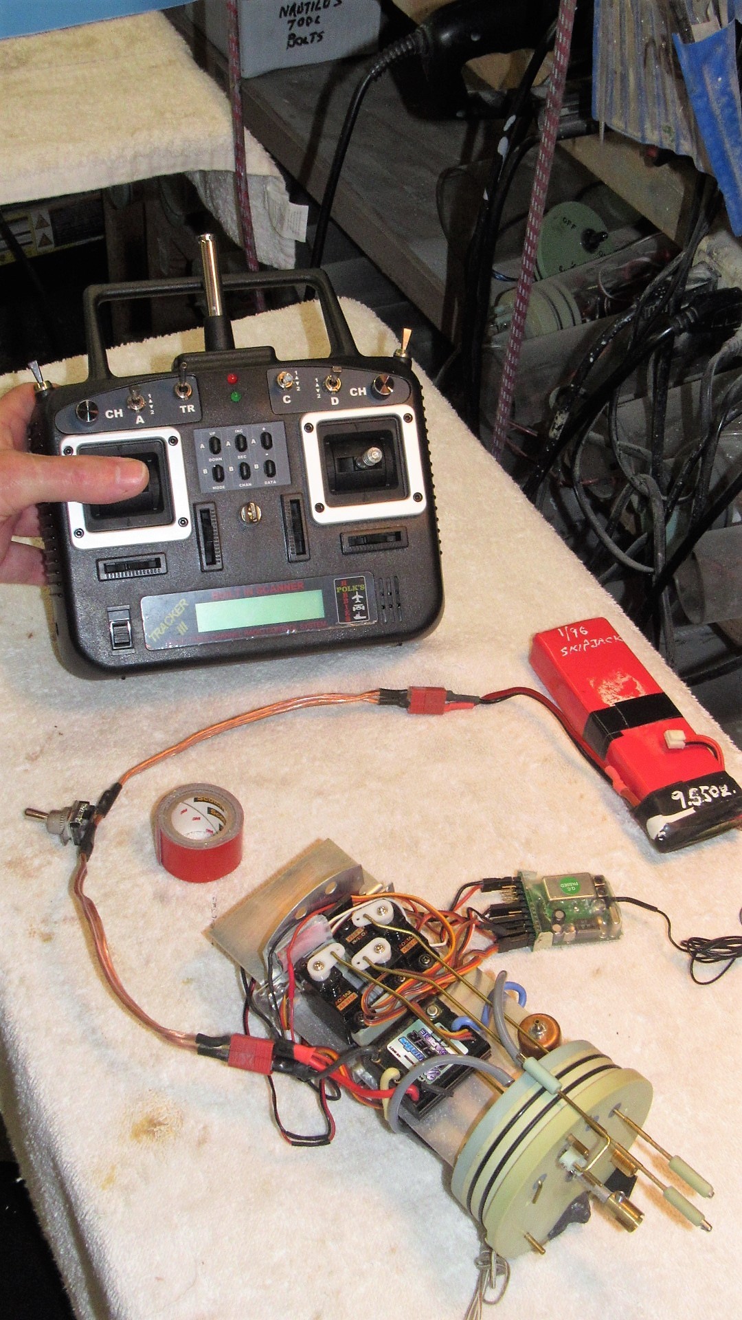
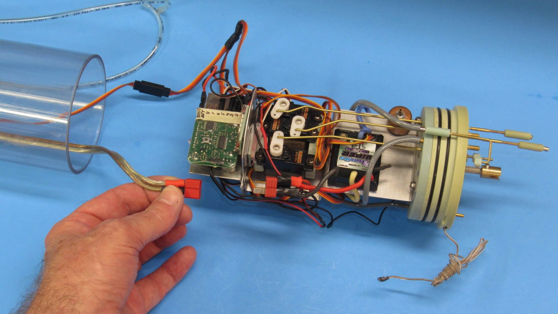
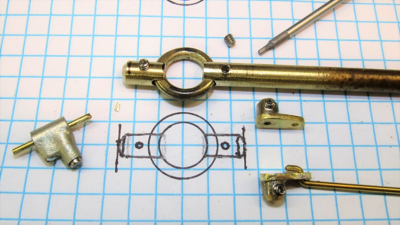
Modern single-shaft submarines usually present the problem of clearing the inter-connected stern plane and rudder operating shafts from the centrally located propeller shaft. Achieving the goal of interconnecting opposed control surfaces is done with a 'yoke' that provides a pass-through to the propeller shaft by providing a ridged structure. One yoke for the rudders, and one yoke for stern planes. This arrangement typified by these shots of the yokes and associated linkages I built for this 1/72 SKIPJACK class submarine kit.
However, at variance to this illustration, the 1/96 STURGEON's stern plane operating shafts will each have their own bell-crank as there is no clearance space between the nexus point of rudders and stern plane operating shafts. Other than that, this photo pretty much represents how the STURGEON tail feathers will be wiggled.
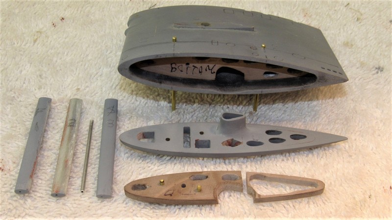
The two standard bell-cranks that would make up to the inboard end of the stern plane operating shafts were constructed from 3/32" bore Du-Bro wheel-collars that had soldered to them sheet-brass arms.
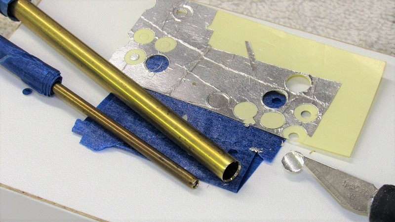
The rudder yoke on the other hand was constructed from a central brass toroid soldered to two bored out lengths of 3/16" brass rod. The trick was to devise a jig to hold the three brass pieces together as I applied solder to join them together.
That cast metal object to the left with the brass rod projecting from each end is a magnetic bell-crank used to rotate the sail-plane operating shafts -- it will be pressed into service (originally a part from our 1/96 THREASHER kit) when it comes time to make the 1/96 STURGEON production tooling.
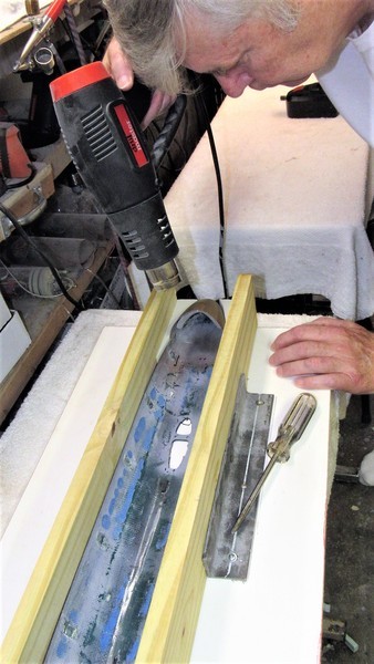
Brass is easy to bend once you anneal the shit out of it. Just take the work to a red heat and let it cool to ambient temperature without quenching. The soft metal handles like putty, but quickly work-hardens, so you have to repeat the annealing till the work is bent and beaten to the shape desire.
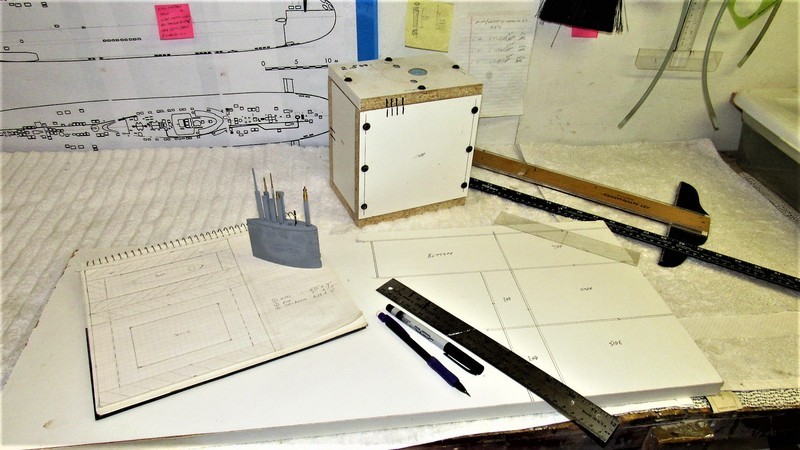
A jig was slapped together from 20 lbs.-per-cubic-foot RenShape. As you can see, the toroid is sandwiched between the two rudder foundations. The jig insures that the shaft bores share the same centerline.
Plenty of free space around the suspended work so nothing catches fire. You don't want any of the jig to off-gas to contaminate the solder-metal union or to act as a heat-sink that would prevent quick, even wetting of the solder to the work. Hence the suspension of the parts in open air.
Two 3/32" diameter brass rods fit the bores of the two rudder shaft foundations. Lead-Tin Solder won't stick to aluminum.
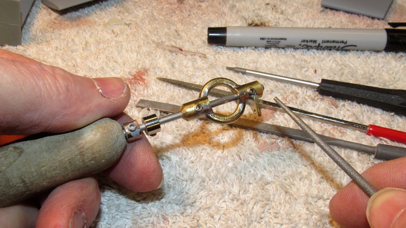
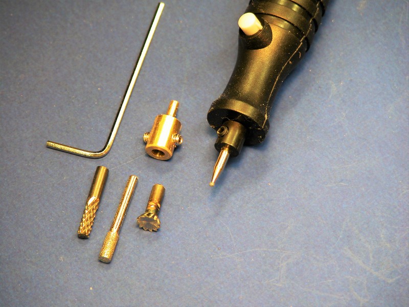
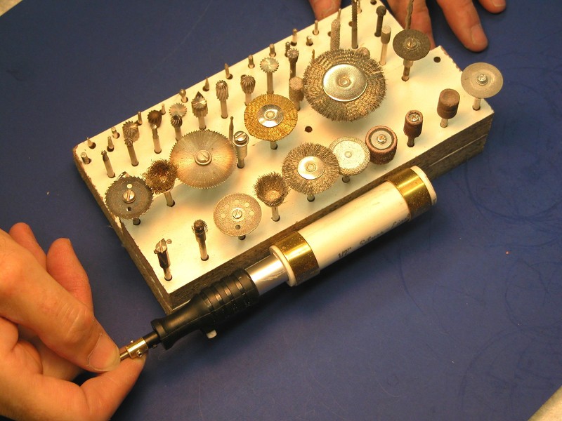
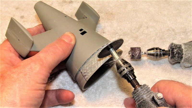
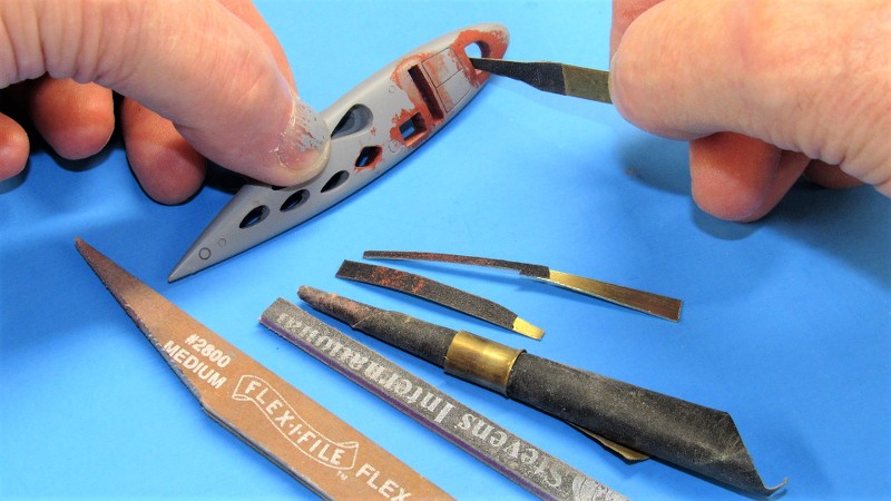
I've made all sorts of part holding tools over the years, I made use of one with a 3/32" spindle as a holding tool as I hand-worked the rudder yoke master. Just slide the master onto the spindle, tighten down on the two set-screws and get to work with files, grinders, burrs, sandpaper, and wire-wheel. Much easier to hold the work this way than to grow calluses on the tips of your fingers!
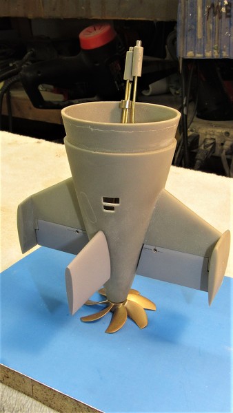
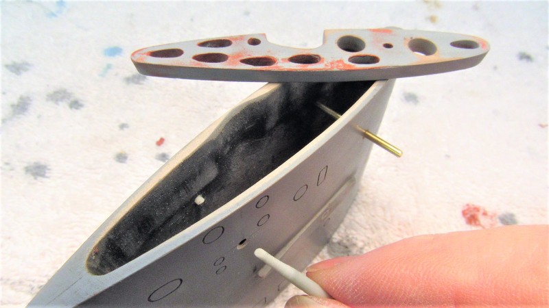
Before adding the bell-crank element to the rudder yoke I first test fit the yoke within the tail-cone master to insure there would be no interference between the port stern plane bell-crank and the proposed location of the rudder yokes bell-crank. Check twice, cut once! Once the position was affirmed to work in the tight confines of the tail cone the bell-crank was added.
Nothing brings a sense of purpose or catches the eye better than the many retractable antennas and optical devices atop the submarines sail. These two illustrations of a Small World Model 1/96 BLUEBACK, with and without masts, makes my point.
Sure, the model submarines sail can be jazzed up with oil-canning paint effects; dry-brushing to highlight edges and high-relief areas; and one can even provide practical dead-lights. But a big opportunity is lost if you don't also equip the display with extended fairings and scope cylinders.

That same model submarine sail with the removable mast farings added -- and the antennas and optical devices atop them -- now becomes something worth looking at. Also, on a practical r/c submarine running near the surface, the feather produced by the masts is a vital visual aid needed by the driver to help him know just exactly where the submerged model is!

Getting back to the 1/96 STURGEON kit. The sail masters: two sail planes; the sail proper; and two alternate sail tops. One sail top with scribed outlines representing the flush fitting tops of the mast fairings, and the other sail top provided with tear-drop shaped holes that would pass mast farings represented in the 'raised' position.
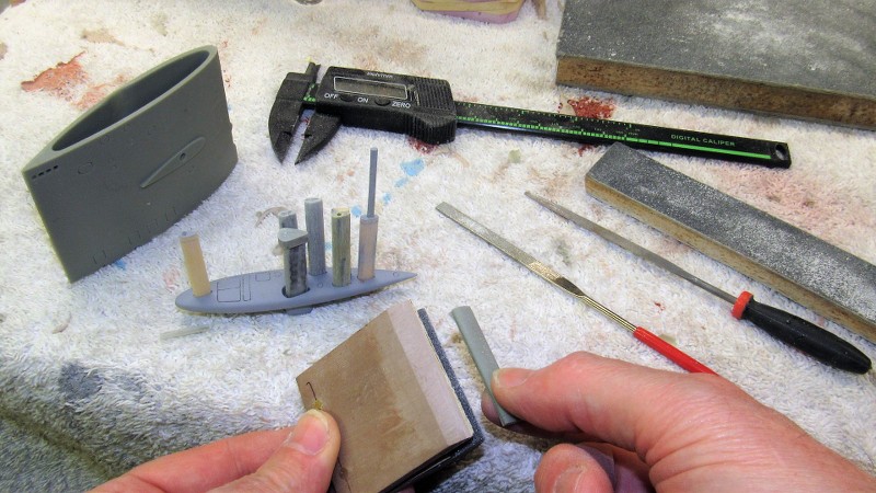
I give the eventual kit-assembler a choice: either represent the model with retracted masts, or raised masts. Here I'm giving final shape with a hand-vice to fairing blanks. Using a sanding block to get them to proper cross-section and thickness

Exacting model-building often required close-in hand-work -- the work firmly held in some kind of hand-vice at eye-level as you work it with the other hand. A jeweler's hand-vice takes many forms, the plastic wedge type above; beneath that a more traditional screw clamping type; and below the more familiar collet types used to hold the cylindrical shank ends of work so equipped.

I make these simple clamp type hand-vices for fragile work that would otherwise bend and break if not supported longitudinally -- such as these highly detailed rows of zincs being carefully engraved and sanded with the aid of this gripping tool. Note that the faces of the two clamp halves have glued to them sandpaper. It's there to assure a no-slip grip to the work. This hand-vice works through the pressure applied with finger and thumb, giving absolute control over clamping pressure.

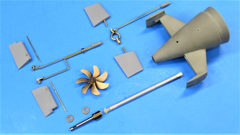
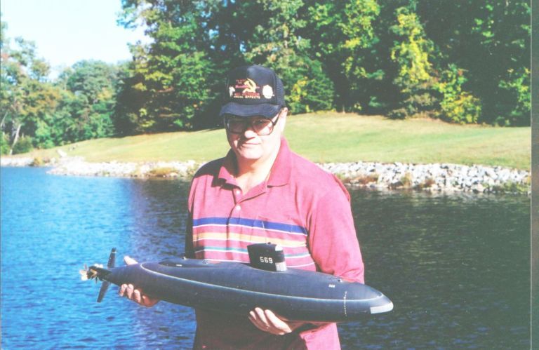
Paralleling the work of making the masters and tools for eventual 1/96 STURGEON kit production is the assembly of a working model. Not only for my personal enjoyment, but primarily serving as a validation article to insure that all kit fit and function problems are identified and solved before committing the masters to tool making. I don't want to unleash a flawed kit on an unsuspecting public -- that would be bad ju-ju!
Three things I get straight before construction begins is to place the center of gravity (center of mass) at the longitudinal center of the hull; position the SubDriver (SD) so the center of the ballast tank is where the assembled models c.g. will be; and place the c.g. as low in the hull as possible to insure adequate static roll stability.
Modern single-shaft submarines usually present the problem of clearing the inter-connected stern plane and rudder operating shafts from the centrally located propeller shaft. Achieving the goal of interconnecting opposed control surfaces is done with a 'yoke' that provides a pass-through to the propeller shaft by providing a ridged structure. One yoke for the rudders, and one yoke for stern planes. This arrangement typified by these shots of the yokes and associated linkages I built for this 1/72 SKIPJACK class submarine kit.


However, at variance to this illustration, the 1/96 STURGEON's stern plane operating shafts will each have their own bell-crank as there is no clearance space between the nexus point of rudders and stern plane operating shafts. Other than that, this photo pretty much represents how the STURGEON tail feathers will be wiggled.

The two standard bell-cranks that would make up to the inboard end of the stern plane operating shafts were constructed from 3/32" bore Du-Bro wheel-collars that had soldered to them sheet-brass arms.
The rudder yoke on the other hand was constructed from a central brass toroid soldered to two bored out lengths of 3/16" brass rod. The trick was to devise a jig to hold the three brass pieces together as I applied solder to join them together.
That cast metal object to the left with the brass rod projecting from each end is a magnetic bell-crank used to rotate the sail-plane operating shafts -- it will be pressed into service (originally a part from our 1/96 THREASHER kit) when it comes time to make the 1/96 STURGEON production tooling.
Brass is easy to bend once you anneal the shit out of it. Just take the work to a red heat and let it cool to ambient temperature without quenching. The soft metal handles like putty, but quickly work-hardens, so you have to repeat the annealing till the work is bent and beaten to the shape desire.

A jig was slapped together from 20 lbs.-per-cubic-foot RenShape. As you can see, the toroid is sandwiched between the two rudder foundations. The jig insures that the shaft bores share the same centerline.


Plenty of free space around the suspended work so nothing catches fire. You don't want any of the jig to off-gas to contaminate the solder-metal union or to act as a heat-sink that would prevent quick, even wetting of the solder to the work. Hence the suspension of the parts in open air.

Two 3/32" diameter brass rods fit the bores of the two rudder shaft foundations. Lead-Tin Solder won't stick to aluminum.

I've made all sorts of part holding tools over the years, I made use of one with a 3/32" spindle as a holding tool as I hand-worked the rudder yoke master. Just slide the master onto the spindle, tighten down on the two set-screws and get to work with files, grinders, burrs, sandpaper, and wire-wheel. Much easier to hold the work this way than to grow calluses on the tips of your fingers!
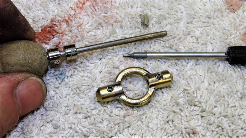

Before adding the bell-crank element to the rudder yoke I first test fit the yoke within the tail-cone master to insure there would be no interference between the port stern plane bell-crank and the proposed location of the rudder yokes bell-crank. Check twice, cut once! Once the position was affirmed to work in the tight confines of the tail cone the bell-crank was added.