Merlin ejector exhausts

steelpillow

Not coming back. Send me a PM.
Top Contributor
Senior Member
Joined
25 June 2014
Messages
1,564
Reaction score
1,453
During the development of the prototype Spitfire K5054, Rolls-Royce developed the ejector exhausts that became such a recognition feature. After several variations, some seen in rare photographs, the exhausts were paired up to create the triple arrangement seen on each side of the early production Merlins. But how and when did this all progress? Received wisdom seems to be that K5084 first received triple ejectors on 19 Sept 1937. However photos from as far back as December 1936 (e.g. Alfred Price; The Spitfire Story, Arms & Armour, 1982, Page 47, or the Spitfire bookazine, Aeroplane Icons, Kelsey, 2013, Page 18) show a "manifold over the exhausts to reduce glare" - one of the professed reasons for the ejectors. Moreover that manifold is clearly divided into three sections, with a rather small rear orifice that suggests not all the gases could have escaped that way.

So just how and when did the triple-ejector exhaust system come about? What exactly were those segmented manifolds doing? Were they being flown on the Hurri and/or Fairey Battle too? Does anybody know of a sensible resource which documents this programme?

Images can be scanned and posted, if that helps.
 
It may or may not help but the following Rolls-Royce patents show the evolution of these exhaust types
GB457936 applied for in June 1935
GB471177 applied for in Nov 1935
GB506333 applied for in Sept 1937 - and this is the key one
 
Hi,

So just how and when did the triple-ejector exhaust system come about? What exactly were those segmented manifolds doing? Were they being flown on the Hurri and/or Fairey Battle too? Does anybody know of a sensible resource which documents this programme?

While there's no direct connection to the early development you're interested in, I thought I might mention NACA-WR-L-680:

"FLIGHT TESTS OF NACA JET-PROPULSION EXHAUST STACKS ON THE SUPERMARINE SPITFIRE AIRPLANE"

See https://ntrs.nasa.gov/search?reportNumber=NACA-WR-L-680

On a Spitfire V with Merlin 45, the original "fishtail" exhausts were replaced by NACA-designed exhaust with 12 ejectors per side, looking a lot like those used on the V-1710 of the P-39, for a top speed increase of 6 mph at the expense of a bit more exhaust flame in some situations.

The contributions of increased exhaust thrust and reduced air resistance of the NACA exhausts could not be separated by the experiment, but the fishtail exhausts sure look very bulky! :)

Regards,

Henning (HoHun)
 
The Rolls Royce Heritage Trust book "Hucknall: the Rolls Royce Flight Test Establishment" by David Birch covers the development of exhaust systems and manifolds, amongst many other engine-related subjects, and might have some info. FWIW, It's a very interesting book (the content is great), spoiled in my opinion by possibly the most inept combination of layout (too narrow inner margins) and binding (pages glued into rigid plastic spine) I've ever come across.
 
I'm not sure that this thread should have been moved to Propulsion as the original question related to the fitment of ejector exhausts to the prototype Spitfire, not to the exhausts themselves
 
Strikes me it could be applied either way as an exhaust would be essential for a powerplant.
 
Some pictures and info here


Seems to be several variations on test.

I always wondered how fast the High Speed Fury was with a Merlin.
 
...................... However photos from as far back as December 1936 (e.g. Alfred Price; The Spitfire Story, Arms & Armour, 1982, Page 47, or the Spitfire bookazine, Aeroplane Icons, Kelsey, 2013, Page 18) show a "manifold over the exhausts to reduce glare" - one of the professed reasons for the ejectors. Moreover that manifold is clearly divided into three sections, with a rather small rear orifice that suggests not all the gases could have escaped that way.
According to "Spitfire The History" that flame-damping exhaust manifold was a late 1936 modification.
Each of the three sections had an elongated outlet opening at the underside.
 
Some additions:
Attached is sketch from mentioned book shows the late 1936 version for flame damper manifold.
With that sketch in mind one can recognize those elongated exhaust openings on the K5054 belly landing photos in Price book p50.

RR tested various types of exhaust manifolds on their He 70 with Kestrel engine since.
In september 1937 K5054 was modified to bring it up to Mk. I production standard. This involved a switch to Merlin II engine and ejector type exhaust manifolds, which directed the exhaust rearward to provide some thrust thereby increasing the plane's top speed.

So the simple 1936 manifolds directed the exhaust gases downward, while the improved 1937 ejector manifolds directed the exhaust rearward. The difference is very difficult to see on old b/w photos so not all authors and readers of books/magazines/websites realize that there is a difference.
 

Attachments

  • Spitfire K5054 Flame-Damping Exhaust (Spitfire The History p31).jpg
    Spitfire K5054 Flame-Damping Exhaust (Spitfire The History p31).jpg
    369.3 KB · Views: 70
This brings us back to the patents I mentioned earlier. The late 1936 setup corresponds to the patent applied for in June 1935 and the ejector type installed in September 1937 corresponds with the design in the patent applied the same month.
 
Some pictures and info here
Type 224 with Y-shaped pipe under the nose.
 

Attachments

  • 570.jpg
    570.jpg
    254.5 KB · Views: 44
  • 571.jpg
    571.jpg
    114.9 KB · Views: 16
  • 572.jpg
    572.jpg
    113.6 KB · Views: 20
  • 573.jpg
    573.jpg
    511.4 KB · Views: 20
  • 574.jpg
    574.jpg
    120.1 KB · Views: 28
K5054 Exhaust manifold December 3, 1936 ???
 

Attachments

  • 579.jpg
    579.jpg
    381.6 KB · Views: 24
  • 580.jpg
    580.jpg
    95.2 KB · Views: 22
  • 581.jpg
    581.jpg
    182.7 KB · Views: 23
Last edited:
K5054 Night flying trials March 23, 1938
 

Attachments

  • 582.jpg
    582.jpg
    891.4 KB · Views: 22
  • 583.jpg
    583.jpg
    154.9 KB · Views: 20
  • 584.jpg
    584.jpg
    222.9 KB · Views: 19
  • 588.jpg
    588.jpg
    429.4 KB · Views: 21
Hawker Hurricane Mk.I with Kidney exhaust stacks
 

Attachments

  • 590.jpg
    590.jpg
    131 KB · Views: 27
  • 591.jpg
    591.jpg
    112.5 KB · Views: 21
  • 592.jpg
    592.jpg
    73.7 KB · Views: 18
  • 593.jpg
    593.jpg
    114.6 KB · Views: 37
  • 42190981754_83d6efa412_b.jpg
    42190981754_83d6efa412_b.jpg
    119.5 KB · Views: 50
Hi Justo,

Hawker Hurricane Mk.I with Kidney exhaust stacks

Thanks a lot! As the diagram with the different exhaust tells me, the NACA report I referenced above does not actually show fishtail exhausts as I thought, but really the "triple ejector, nozzle outlet" variant.

I believe that's in fact the same as on these photographs of K5054:


So K5054 seems to have been fitted the following exhaust variants:

- flush with cowling
- "kidney" with downward facing slots
- "kidney" with rearward facing nozzles below
- "triple ejector, nozzle outlet"

Would that appear to be a correct summary, or am I missing something?

Regards,

Henning (HoHun)
 
Not quite. Using your nomenclature the correct sequence was:

- flush with cowling (Not quite flush though, stubs stuck out a little)

- "kidney" with downward facing slots (The late 1936 type)

- "triple ejector, nozzle outlet" (The september 1937 type. Was used during january 1938 night trials and as a result was considered unsuitable for night use)

- "kidney" with rearward facing nozzles below ("Modified Blister type" as in 582.jpg and 583.jpg above. These were used during march 1938 night trials but were not found to give any improvement. K5054 had a night landing accident 24 march and did not fly again until months later.)

- Not clear what type exhaust manifold was used after march 1938 until the final crash of K5054 in september 1939. Could be again the "triple ejector, nozzle outlet"

After the night landing accident in march 1938 and subsequent repairs and modifications K5054 was used months later for gun heating trials.

In the mean time the first production Mk.1 Spitfire K9787 had made its first flight in may 1938 and further tests with different exhaust manifolds were done using this plane.
 
Last edited:
Does anybody have a picture of the "cross over exhaust system" as it was called which was used on the civil Merlin powered Northstar? It must have provided some noise reduction in the cabin and increased performance, but I cant find a primary source or any pictures of it.
 
Don't know whether this was the final design but it gives some idea:

North Star  cross-over exhaust system.jpg

Source: CASM-Aircrafthistories-CanadairNorthStar.pdf
which can easily be found via google.
 
Thanks, but my Google didn't find it... Hard to believe, that this arrangement would have improved the performance...

I will do some more googleling later
 
Found here: http://warbirdinformationexchange.org/phpBB3/viewtopic.php?f=3&t=3810, from exchange-member airnutz
It has been several years since I read "The Canadair North Star", by Larry Milberry, 1982.... and of course I remembered a detail wrong. The exhaust mod I referred to earlier was actually developed to reduce the noise levels within the cabin of the North Star created by the hammering effects of 4 sets of exhaust stacks aimed at the occupants.

A Trans-Canada Airlines technical innovator, Merlin "Mac" MacLeod (No Sh*t, Merlin was his real name) developed and designed an "exhaust gas crossover manifold", which ducted the inboard-facing stacks over the Merlin...using a large single collecter tube...which joined to 3 outboard fish stacks resulting in projecting some of the noise away from the cabin. A benefit of this design, was the flames of the exhaust were no longer in view of the passengers at night. On the TCA North Star this "crossover manifold" was built somewhat over the original cowling and a fairing was designed which "dirties-up" the original smooth lines.

And as Mike said, BOAC operated the same aircraft christening it Argonaut. BOAC came up with their own "crossover manifold" which used 3 smaller tubes running alongside each other over the engine and joined into a outboard "ejector" manifold which also doubles as the outboard exhaust bank exiting 3 round exhaust stubs angled aft. A benefit of BOAC's 3-tube design, was the profile of the cowling remained clean and sleek, as the manifold assembly was within the confines of the cowl framework.
From Canadian Aircraft since 1909 by K.M. Molson & H.A. Taylor, Putnam 1982, p302-303:
North Star crossover.jpg
 
Last edited:
Thanks, but my Google didn't find it... Hard to believe, that this arrangement would have improved the performance...

I will do some more googleling later
That arrangement probably didnt, but, if you did it to both sides, you could probably get the lengths into the zone where resonance tuning becomes possible at those low engine speeds, which might have been able to increase cylinder filling. However, considering the weight and extra space needed, its debatable if there would have been any net increase in speed should you have done it as I`ve suggested.
 
Yet more to be found here:
Text:
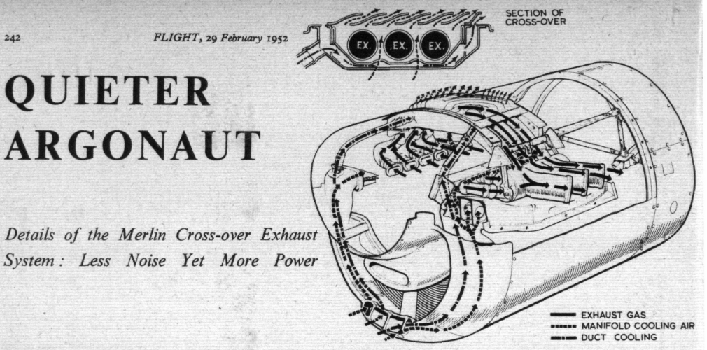
First announced some months ago, the cross-over exhaust system developed for the Merlin T.M.L.* power plant by Rolls-Royce, Ltd., is now entering B.O.A.C. service—in particular, all four engines of the Argonaut Atalanta, in which H.M. The Queen recently flew to Kenya and back, were fitted with it.
Both Rolls-Royce and B.O.A.C. have long appreciated the fact that the Argonaut (Canadair DC-4M) could well be made a quieter aircraft; to do so, however, and lose nothing in the way of performance, was a much greater problem, and Rolls-Royce have spent a considerable period in finding the best solution. It must therefore be with some gratification that they can now announce the development of this new exhaust system which, while effecting a marked reduction in noise level, actually improves performance.
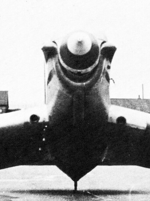
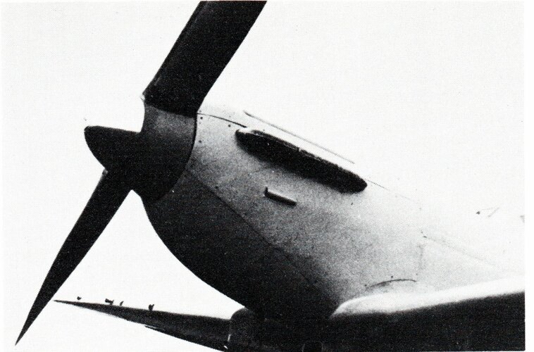
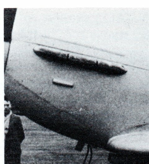
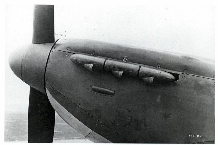
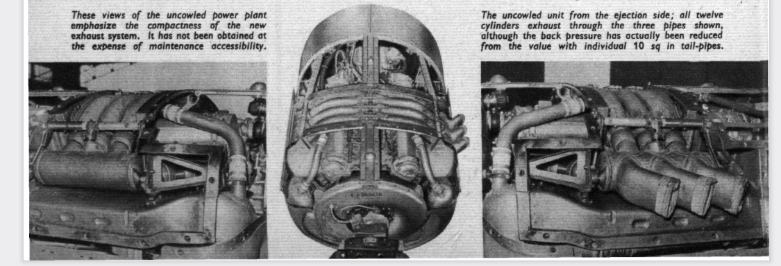
B.O.A.C. recently afforded us the opportunity of examining this new power plant —redesignated Merlin T.M.O.— at London Airport, and the accompanying photographs show the system to good advantage.
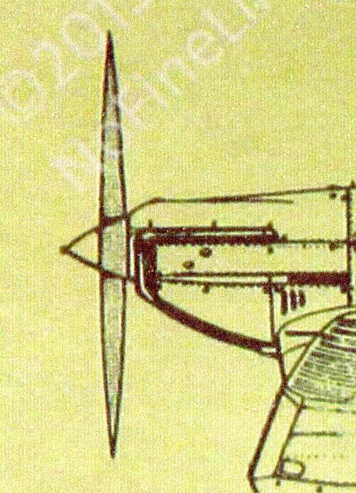
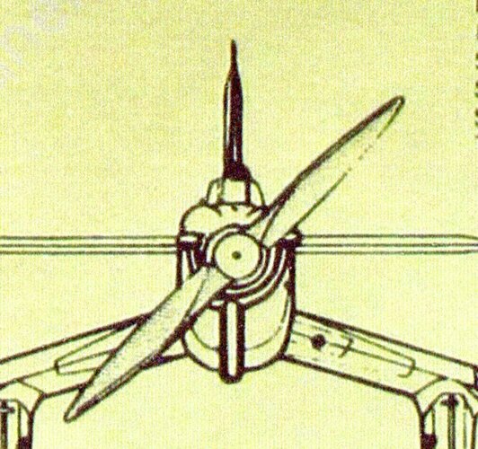
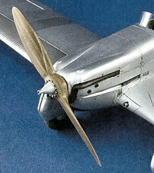
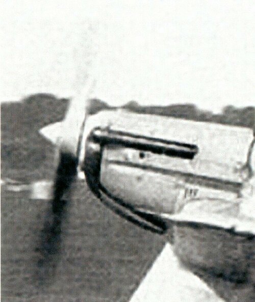
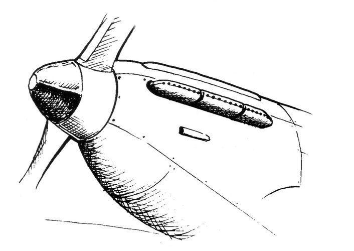
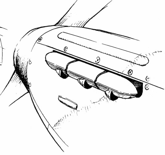
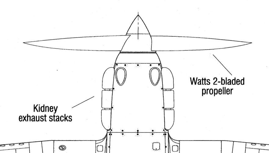
Beside each cylinder bank, and suspended from a sub-frame off the main bulkhead, is a cylindrical manifold into which the adjacent cylinders exhaust via ball-jointed stubs. The two manifolds of each power plant are symmetrically connected by three stainless-steel pipes which carry the exhaust from the inner bank of each engine over to the outer manifold; final release to atmosphere is made through three stubs ejecting on the outer side of each cowling.
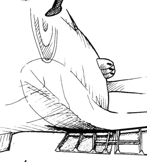
The manifolds and primary exhaust stubs are made of Inconel, and are designed to be free from stresses arising from engine vibration, while affording the clearest possible gas path. The system is cooled by air drawn in at an intake placed centrally on the lower lip of the main radiator intake.
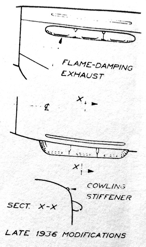
This position receives the full benefit of both airscrew slipstream and ram air, and results in effective cooling under all conditions. From the new intake the flow is divided, one stream cooling the primary stubs and the adjacent ignition harnesses, while the other passes over the connecting pipes; both exhaust from herringbone-shaped louvres above the cowling.
The cross-over modification also involves replacement of the existing main coolant radiator by a unit made entirely of light alloy, while a new circular brass oil-cooler is also specified. The modified power plant is interchangeable port and starboard by fitting the appropriate ejector-stubs to the outer side of the engine, and the correctly handed blanking-plate on the fuselage side. The new exhaust system is completely interchangeable with the original system, the only parts affected being the valve rocker-box covers, ignition harness, and fire extinguishers, all of which are supplied by Rolls-Royce in the modification kit.
The reduction in noise is achieved both by exhausting away from the fuselage—exhaust flow, incidentally, is entirely above the wing—and also by the mutual cancellation of many of the harmonic constituents of the noise spectrum. Throughout, close attention has been paid to providing unrestricted gas-flow, and to reducing installation-drag; the result has been a back-pressure reduction giving an additional 38 b.h.p. at maximum power per engine in comparison with the original Merlin T.M.L., while the cleaner installation results in a gain in T.A.S. of some 5 kt over the range of cruising speeds. The factors combine to increase the specific air range of the Argonaut by some 4 per cent, and to reduce the noise level by between 5 and 8 decibels; the greatest silencing effect is obtained in the higher frequencies, which are those most affecting passenger comfort.
The penalties involved appear to be negligible; the [could not locate next page]

* "T.M." denotes "Transport Merlin" and is followed by a serial letter.
 

Attachments

  • Crossover 1.png
    Crossover 1.png
    637.8 KB · Views: 29
  • Crossover 2.png
    Crossover 2.png
    449.4 KB · Views: 33
Last edited:
Thanks to all for the very interesting and detailed links!

This system is quite complex and looks a bit bulky, they must have done a very good job to make it work more efficiently than the original configuration!

The improvement of performance might be partially because the cross over pipes might act like a tuned exhaust manifold like Calum wrote (a well designed exhaust manifold on a naturally aspirated engines gives more power than single exhaust stacks), but I guess the modified cooling system also mentioned was the main reason for the increased speed. A mechanically supercharged engine in great height (30.000 ft !) with a free exhaust without mufflers, catalyst etc. will have so little back pressure, that most of the time the pressure drop over the exhaust valve will be above the Laval pressure condition. In this case, the exhaust flow is not influenced by the back pressure at all. At the end of the exhaust stroke (with lower pressure drops), when a tuned exhaust system can provide suction pressure which helps to clean the combustion chamber, the gain will be very limited compared to an open exhaust stack which leads to an atmospheric pressure of just 0,29 bar.
As can be read in the text, the back pressure was lowered compared to the former individual nozzle design, this will surly help, but mainly at lower altitudes when the pressure ratio between the cylinder during the exhaust stroke and the atmospheric pressure is not as high as in 30.000 ft. I’m pretty sure, that the cross over system delivered less thrust than the original configuration, which was overcompensated by lowering the exhaust back pressure and redesigning the cooling system.
 
Something about the Laval condition and the terrible energy losses during the exhaust phase (in German, but the diagram should be understandable):

http://www.mb.fh-stralsund.de/fss/pages/pg_lehre/FLM II/Vorlesung Teil2 ab Laval Düse.pdf

As we see, the laval pressure ratio is somewhere between 0.5 and 0.6 depending on the kappa of the gas. If we assume, that the we have about 2 bar absolute and 350 K in the cylinder at the beginning of the compression stroke and about 1200 K at the beginning of the exhaust stroke, the pressure inside the cylinder will be around 7 bar absolute. In an ideal world we would expand the exhaust gases from around 7 bar to about 0,3 bar (atmospheric pressure at cruise height) and use all of the energy potentiyl. Unfortunately, this is hard to do, in a turbocharged engine, we blow down the pressure to a level which is about similar to that of the charge pressure before we feed it to the turbine of the turbocharger. A single exhaust stack can use all the energy, but with a very low efficiency. A turbocharger in a conventional turbocompound system can use only a fraction of this energy potential (due to the lower back pressure), but with a high efficiency. There are ways to use even more of that (e.g. by Miller timings) but no established system close to the full potential. One approach which makes best use of this potential can be seen here:

https://www.secretprojects.co.uk/threads/diesel-turbocompound-fan-propulsion.40548/

The engine is working with an exhaust back pressure which is relatively close to the in- cylinder pressure at the beginning of the exhaust stroke. In this case, the piston will do a lot of additional work, which can only partially be recovered by the turbine. This only makes sense, if you have a turbine with an extremely high efficiency. By using a regular turbine from a jet engine, this is the case and the reason why this turbocompoundsystem can achieve about 50 % efficiency.
 

Similar threads

Back
Top Bottom