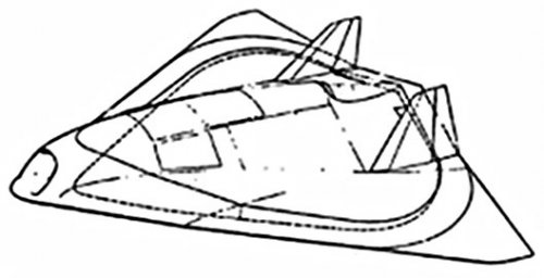
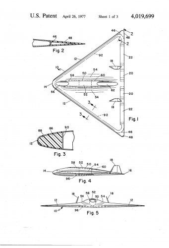
An aircraft which has a very low observability visually and to radar, thel and acoustic detecting devices. The aircraft is designed to have as few edges and surfaces as possible, such as a delta wing type, the edges being straight, or near straight and the vertices rounded. All surfaces are as...
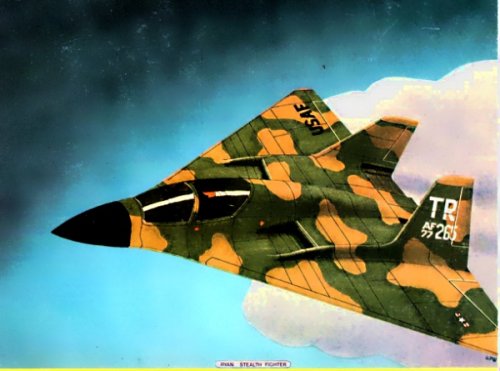
I know I've seen a McDD patent that is exactly like that model pictured. While looking through patents to find it I did find the TR patent above, which is a close match. I have noticed that for manned aircraft TR would often partner up from the mid-70s on.
"Have Blue and the F-117A: Evolution of the Stealth Fighter "documents the history, observations, and lessons learned from the development and acquisition of the first very-low-observable combat aircraft. The book is a case study of the high-payoff, low-profile strike fighter development effort...
books.google.com
McD's original HAVE BLUE was apparently based on their earlier Quiet Attack Aircraft concept. Teledyne Ryan had proposed to USAF to pursue the low RCS RPV shown in patent 1 in this thread. McD and TR teamed up, creating the concept in patent 2, which was the McD/TR team's HAVE BLUE/XST design.
As Quellish indicates Teledyne & McDonnell-Douglas definitely worked on XST together according to the most definitive source on this program.
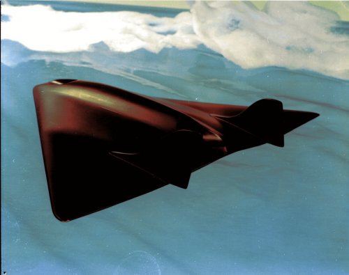
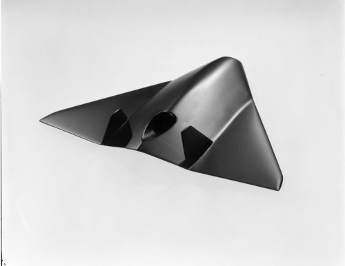
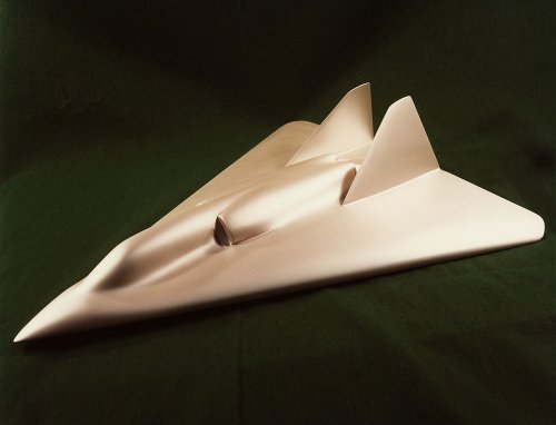
The Model 268 XST is clearly based on the basic principles and layout of the Teledyne stealth work as opposed to the earlier McDonnell-Douglas Quiet Attack design which is entirely based on curves, not straight lines. It has higher wing sweep, probably (like on HAVE BLUE) due to the severe front quarter RCS requirement, and the engine installation looks more like a small scale demonstrator than a full size airplane, but other than that its pretty close.
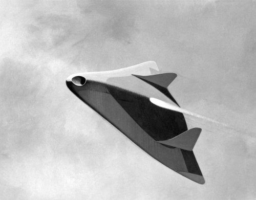
The original 1973 study (essentially a metal flying saucer inside a radar transparent flying wing) from Aronstein & Piccorillo plus 1975 Navy study, the Teledyne Model 262 Manta Ray (http://www.designation-systems.net/dusrm/app4/tra-262.html)
Fair enough. The Teledyne Ryan design seemed a little more advanced with its blended intakes/exhausts and the absence of a detached nose... Hence my question. Also, I read somewhere (on this forum and elsewhere I think) that McDonnell Douglas's "Marshmallow" design (the one at the bottom) was merely devised as a decoy to fool observers as to the real shape and configuration of the real XST design...
Oh, I see. I was mistaking these two illustrations as being two forms of the same project, given their many similarities. It is really the dorsal air intake that makes the difference, isn't it? Wings are slightly different, but I've seen more different designs being covered by one single model number before...
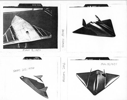
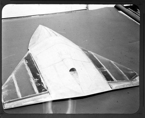
Possibly. The configuration of SANDY HOOK matches:
"The second was a 125,000-foot altitude, intercontinental, subsonic drone with hydrogen engines and very stealthy delta wing design built by Teledyne Ryan Aeronautical in the early 1970s. It was to be completely invisible to radar at that altitude because it had a radar cross-section of a dime. The proposed $400 million program, called Sandy Hook, never made it to flight test. The development costs for both UAVs probably never exceeded $30 million. Robert R. Schwanhausser, Ryan’s Sandy Hook program manager, interview, July 7, 1999."
From Aronstein, D. C., and Piccirillo, A. C., Have Blue and the F-117A: Evolution of the "Stealth Fighter," AIAA, Reston, VA, 1997, pg 11:
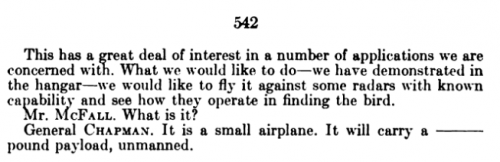
Accordingly, in 1971, a new Air Force prototyping study team recommended the development of a very low radar cross section test vehicle as part of a Department of Defense (DoD)-wide move toward advanced prototyping initiated by Deputy Secretary of Defense David Packard. The very low RCS test vehicle was proposed by Teledyne Ryan, and was one of six programs that the study team recommended from a field of 45 candidates, noting that
...the capability to achieve extremely low radar cross sections has been demonstrated by large scale, nonflying test models.... The capability to remain "invisible" to radar so radically changes the posture of most offensive and defensive systems that prototype testing to confirm this capability is warranted
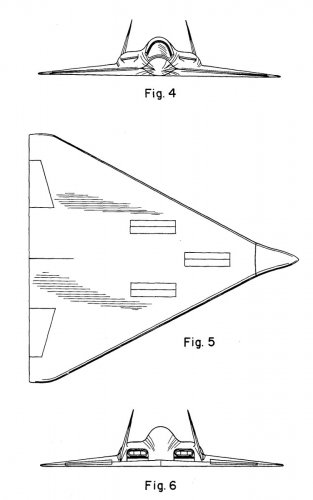
Teledyne Ryan proposed to build and flight test three unmanned aircraft. The proposed design was almost certainly similar to the delta-wing shape, illustrated in Fig. 5. Gross weight would be approximately 3000 lb. The aircraft would be subsonic but capable of very high altitude flight. Launch would be accomplished from a modified C-130 was recovery by the existing mid-air retrieval system (MARS) as used by their earlier AQM-91A Compass Arrow and other drones.
From Aronstein, D. C., and Piccirillo, A. C., Have Blue and the F-117A: Evolution of the "Stealth Fighter," AIAA, Reston, VA, 1997, pg 203:
Teledyne Ryan Low RCS Vehicle Study (1973-1974 Design Study)
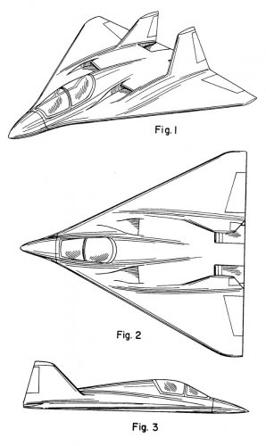
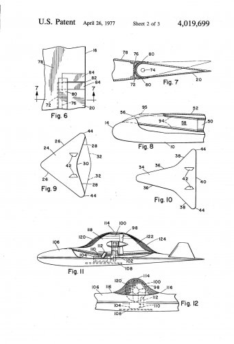
The Remotely Piloted Vehicle Special Projects Office at Wright-Patterson Air Force Base, Ohoi conducted studies and tests in conjunction with Teledyne Ryan and other companies of low RCS drones. Having learned from experience with the AQM-91A Compass Arrow that a conventional, wing-body-tail arrangement would not acheive very low signatures, Teledyne Ryan advanced to a more aggressive approach involving simpler planforms with fewer surfaces and edges. The Teledyne Ryan Low RCS Vehicle, illustrated in Fig. A11, was to consist of a small metal centerbody surrounded by a large amount of lossy dielectric material. The configuration was all-wing with a simple delta planform and inward-canted twin vertical tails. The engine and equipment were buried in the fairly thick wing root. Tail surfaces and other features were to be made of "radar-transparent" materials. Overall dimensions would be approximately 18 ft in overall length and 21 ft in wingspan.
The Low RCS Vehicle study (AFAL-TR-74-320) is available through the GWU National Security Archive: http://www2.gwu.edu/~nsarchiv/NSAEBB/NSAEBB443/docs/area51_12.PDF
While illustrations of the vehicle have been redacted, it does specifically identify it as Model 237. It also specifically mentions patent application "SN465,540". Patent 4019699 (https://www.google.com/patents/US4019699) appears to be the Low RCS Vehicle or it's immediate predecessor, but has a different patent application number.
Scott has a good illustration of the Low RCS Vehicle: http://up-ship.com/blog/?p=16971
This is the redacted Figure 6 from the study paper above.
From Aronstein, D. C., and Piccirillo, A. C., Have Blue and the F-117A: Evolution of the "Stealth Fighter," AIAA, Reston, VA, 1997, pg 205:
Teledyne Ryan Mini-RPV (1974-1975)
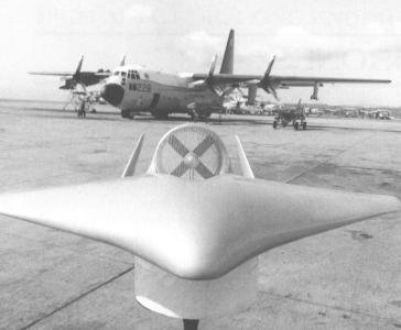
The 7.5-ft wingspan Teledyne Ryan Mini-RPV followed the same shaping approach as the Low RCS Vehicle, but it specifically avoided reliance on RAM. Several versions were proposed with variations in the tradeoff between radar treatment, countermeasures, and overall system cost. As shown in Fig. A12, it was powered by a ducted fan on the top side of the vehicle, and in some variants it was intended to use wire screens over both ends of the duct, as well as over the sensor package on the vehicle's underside. In RCS testing, Mini-RPV models met or exceeded signature goals that were based on achieving survivability through a combination of RCS reduction and countermeasures. Some Mini-RPVs were built and flown, although it is unknown wether any of these represented a low-RCS configuration or wether any in-flight RCS testing was ever performed.
Neither the Mini-RPV nor the Low RCS Vehicle achieved sufficiently low signatures to avoid detection completely while performing a useful military mission. However, they did provide what was perhaps the first credible indication that such a goal could be accomplished. Many radar systems did not perform at all well against these targets. The lesson was not wasted. Several of the people involved in these projects at the Air Force's RPV office later played key roles in formulating and managing the Have Blue program.
The Low RCS Vehicle Study paper mentions the Mini-RPV, and specifically that it did not incorporate the RAM edge treatments described in the paper because they were not available.
The Model 262 was built for the Navy's Shipboard Tactical Airborne RPV program. It was flight tested in 1976-1978(?).
In 1975 several tests were conducted at China Lake to explore RPV signatures using a BD-5 (N5390). The BD-5 acted as an RPV surrogate and flew through a dynamic RCS range set up at Randsburg Wash. You can seem some photos of this here: http://www.chinalakealumni.org/1975/1975.htm
The Mini-RPV was later flown against the same dynamic range at Randsburg Wash to verify it's in-flight radar cross section.
The Mini-RPV is the Model 262. SDASM has posted quite a few images of it on Flickr: https://www.flickr.com/search/?w=49487266@N07&q=Model 262
The Low RCS Vehicle Study paper mentions the Mini-RPV, and specifically that it did not incorporate the RAM edge treatments described in the paper because they were not available.
The Model 262 was built for the Navy's Shipboard Tactical Airborne RPV program. It was flight tested in 1976-1978(?).
In 1975 several tests were conducted at China Lake to explore RPV signatures using a BD-5 (N5390). The BD-5 acted as an RPV surrogate and flew through a dynamic RCS range set up at Randsburg Wash. You can seem some photos of this here: http://www.chinalakealumni.org/1975/1975.htm
The Mini-RPV was later flown against the same dynamic range at Randsburg Wash to verify it's in-flight radar cross section.
We DO have a topic on the Model 262, also known as the Manta Ray. Unfortunately it is not very conspicuous because for some obscure reason it is filed under "Designation Systems"...
As this concerns the TR UAV programs that lead to the Model 268 XST (and, in fact, are what prompted the HAVE BLUE program itself), this topic seemed like the best place for it. If it is not I can remove my post.
As this concerns the TR UAV programs that lead to the Model 268 XST (and, in fact, are what prompted the HAVE BLUE program itself), this topic seemed like the best place for it. If it is not I can remove my post.
I never implied that it was out of place, nor did I give the link to indicate a desirable move. It was merely to lead those who want to know more about the Model 262 to its dedicated page.
Compared to drawing, span looks wider, vertical tails are slightly different and elevons placed differently but clearly the same basic concept. My guess would be the painting is a later revision.
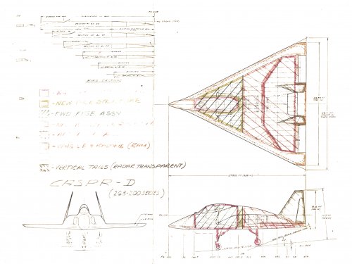
A new donation to the Museum contained this drawing which has similarities to other designs in this thread. The scan doesn't bring it out too well but the red sections are referenced as A4 (A-4 Skyhawk?) and the cockpit section would appear to be a close match and as I recall, the wing fuel tank looks similar to the A-4 as well. So, possibly a proof of concept design?
Any thoughts on the meaning of CASPR-D? "Casper the Friendly Ghost" comes to mind....
Different versions, yes, but the same design. I mean that the drawing shows that the inlets are recessed slots to hide them from side view as opposed to what looks like a simple pitot-type intake on the model. The drawing is labelled as 268-200 series.
I imagine someone decided to call it after Casper the ghost and then came up with the acronym. Its interesting to compare with Lockheed 'Harvey' I wonder what the Northrop XST name was
This site uses cookies to help personalise content, tailor your experience and to keep you logged in if you register.
By continuing to use this site, you are consenting to our use of cookies.


") I wonder what the Northrop XST name was
I wonder what the Northrop XST name was