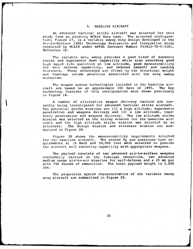
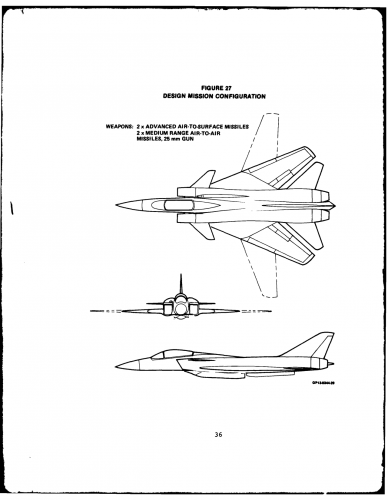
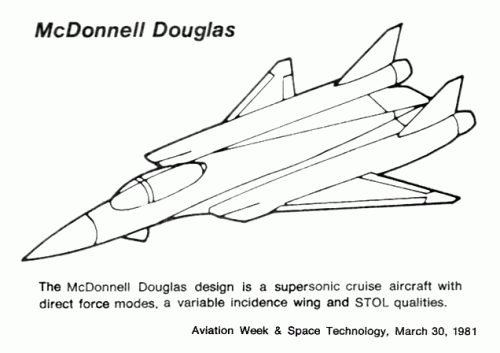
For those thinking the above model (the one circled in red) is McDonnell Douglas' ATF design, here's their original, declassified painting. The wing trailing edge and the rear end of both aircraft are different. Maybe it's an earlier submission, but it would be interesting if a full picture of that model could be revealed. Since it was a Lockheed Martin event, it's probably a Lockheed or General Dynamics ATF design.

On a side note, I wish Jay Miller in his F/A-22 Aerofax book would have properly identified General Dynamics' pre-ATF and ATF designs (pretty much everything from pages 7 through 13) as being their designs, not Lockheed's. I have to say that is a disservice to both the enginers at General Dynamics and at Lockheed from that period. An enthusiast like me knows it, but just anyone picking up the book may not.
 

Attachments

  • untitled.JPG
    untitled.JPG
    49.1 KB · Views: 972
sferrin said:
overscan said:
Jay took photos of every model, but he doesn't have easy access to the negatives. The book doesn't have a photo of the design.

I wonder if Scott happened to get any of the ATF stuff in his haul when he visited Jaay Miller's archive. ???

Nope.

1) The archive is split into roughly three equal collections in three distinct loctions... I only got to one of them
2) I never came across negatives
3) Even if I had, I didn't have the equipment to do anything with 'em.

Some day I'd like to get back and visit Location 2. Sigh.
 
Merged topic with ATS topic, as ATS is the first stage of evolution towards ATF and the topics are overlapping.
 

Attachments

  • Model252-2BF-3.JPG
    Model252-2BF-3.JPG
    16.1 KB · Views: 360
Although it was a very high performance vehicle, the Model 252-2BF-3, a typical SX configuration fixed-wing attack aircraft, proved to suffer in the ratings due to lack of firm design and payoff information, Figure 2. Also, the then relatively undefined high-speed performance indicated a wing temperature condition that would require a thermal/structural analysis and materials other than the well characterized epoxy matrix composites

Appears to be a highly supersonic (hypersonic?) attack aircraft design.
 
Hi,

the MD aircraft P ,it was not related to MD-265.
 

Attachments

  • MD P aircraft.JPG
    MD P aircraft.JPG
    87.3 KB · Views: 815
This image is from the Model 265 thread, and that design shown in Hesham's post sure looks like a shorter tailed version of the one shown on the far right, as Overscan was alluding to ;)

Here's Mark Nankivil's post for reference

index.php


BTW Hesham, I have that book as well. It has alot of cool stuff in it, but I wouldn't rely on it for accuracy. ;)
 
overscan said:
Really Hesham, so why does it look exactly like the Model 265?

::)

My dear Overscan,

from the same book,you will see the different between two projects,
this aircraft had a one tail fin but the MD-265 had twin tail fin.
 

Attachments

  • MD P aircraft.JPG
    MD P aircraft.JPG
    87.3 KB · Views: 687
  • MD pre-ATF.JPG
    MD pre-ATF.JPG
    108.1 KB · Views: 803
Hesham, "Aircraft P" is not the designation of this design. The book has a lot of concept art where the author had no designation so he simply captioned the pictures "Aircraft A" to "Aircraft Z".

I agree its not quite the same as the 265 drawing you show, but the differences are minor and its clearly part of the 265 design effort.
 
What it comes down to is we don't have a model number for that design and it obviously uses the vectored lift system of the Model 265. We just don't know if it was a development of the model 265, i.e. model 265-"whatever," or if had it's own model number. Perhaps Mark will be able to dig up some info regarding this issue for us from the archives in the future.

Of course, I'm hoping he finds info on that hypersonic design, but that's a whole other topic. ;)
 
overscan said:
Hesham, "Aircraft P" is not the designation of this design. The book has a lot of concept art where the author had no designation so he simply captioned the pictures "Aircraft A" to "Aircraft Z".

I agree its not quite the same as the 265 drawing you show, but the differences are minor and its clearly part of the 265 design effort.

Ok my dear Overscan,

and I think my dear Flateric is right,it looks like the Aircraft P exactly
 
Bunch of windtunnel photos of some early 1980s McDonnell-Douglas (McAir) advanced fighters here:


Attachments

  • L-83-8300[1].jpg
    L-83-8300[1].jpg
    440.6 KB · Views: 225
  • L-83-8299[1].jpg
    L-83-8299[1].jpg
    432.5 KB · Views: 209
  • L-83-8298[1].jpg
    L-83-8298[1].jpg
    442.8 KB · Views: 213
  • L-83-8297[1].jpg
    L-83-8297[1].jpg
    428 KB · Views: 648
  • L-83-8296[1].jpg
    L-83-8296[1].jpg
    429.1 KB · Views: 663
  • L-83-8295[1].jpg
    L-83-8295[1].jpg
    470.5 KB · Views: 678
  • L-83-8293[1].jpg
    L-83-8293[1].jpg
    493.4 KB · Views: 791
  • L-83-8294[1].jpg
    L-83-8294[1].jpg
    463.6 KB · Views: 939

Attachments

  • L-83-8303[1].jpg
    L-83-8303[1].jpg
    440.5 KB · Views: 191
  • L-83-8302[1].jpg
    L-83-8302[1].jpg
    446.6 KB · Views: 195
  • L-83-8301[1].jpg
    L-83-8301[1].jpg
    426.7 KB · Views: 219

Attachments

  • L-85-5700[1].jpg
    L-85-5700[1].jpg
    404.6 KB · Views: 191
  • L-85-5698[1].jpg
    L-85-5698[1].jpg
    381.3 KB · Views: 168
  • L-85-5697[1].jpg
    L-85-5697[1].jpg
    403.5 KB · Views: 188
  • L-85-5694[1].jpg
    L-85-5694[1].jpg
    439.2 KB · Views: 133
  • L-85-5696[1].jpg
    L-85-5696[1].jpg
    470.2 KB · Views: 127
  • L-85-5695[1].jpg
    L-85-5695[1].jpg
    431.5 KB · Views: 130
  • L-85-5693[1].jpg
    L-85-5693[1].jpg
    428.9 KB · Views: 162
Last edited by a moderator:
The USAF Wright Laboratory (WL), NASA Langley Research Center (LdRC), NASA Lewis Research Center (LeRC). and McDonnell Aircraft Company (MACAIR) nave performed a comprehensive aerodynamic investigation of the impact of LO forebody shaping on inlet approach flowfields over the past six years (1985-1991). This investigation evaluated flowfield characteristics for three generic advanced fighter inlet integration concepts. These concepts were designed to have reduced RF signature, supersonic cruise capability. and enhanced maneuver performance relative to currentside-mounted inlet configuration, a top-mounted inlet configuration, and a wing-shielded inlet configuration. The study used high speed wind tunnel flowfield surveys to quantify the inlet approach flowfields. These flowfield properties were averaged across candidate inlet apertures to assess integrated inlet performance and. compatibility potential. This data was then used to develop new design guidelines for the integration of inlets into LO-configured forebodies.

AIAA-91-2599
The Impact Of LO-Configured Forebodies On Inlet Approach Flowfields
R. C. Haddad And D. C. Bingaman
McDonnell Douglas Corporation
St. Louis, MO
L. E. Surber
Air Force Wright Laboratory
WPAFB, OH
E. A. Bare
NASA Langley Research Center
Langley, VA
AIAA/SAE/ASME
27th Joint Propulsion Conierence
June 24-26, 1991 / Sacramento, CA
 

Attachments

  • LANGLEY_AFRL_MDC_LO_FOREBODY_STUDIES.jpg
    LANGLEY_AFRL_MDC_LO_FOREBODY_STUDIES.jpg
    226.3 KB · Views: 523
Hi,

http://www.dtic.mil/cgi-bin/GetTRDoc?AD=ADA060206&Location=U2&doc=GetTRDoc.pdf
 

Attachments

  • 1.JPG
    1.JPG
    22.2 KB · Views: 328
  • 2.JPG
    2.JPG
    22.5 KB · Views: 270
  • 3.JPG
    3.JPG
    24.9 KB · Views: 249
  • 4.JPG
    4.JPG
    21.4 KB · Views: 251
SF-1107 can be seen in this painting earlier in the topic:

index.php


http://www.secretprojects.co.uk/forum/index.php/topic,399.msg69229.html#msg69229
 
SF-1302 can be seen in this painting and plan posted earlier in this topic:

index.php


http://www.secretprojects.co.uk/forum/index.php/topic,399.msg69223.html#msg69223

index.php


http://www.secretprojects.co.uk/forum/index.php/topic,399.msg4378.html#msg4378
 
Because I am not a aerospace engineer nor a aerodynamicist I was wondering if someone at SP could help me. You see a lot of fighter concepts with engines "on top of the wings/fuselage" but none that I know of built. Are there any inherent advantages or disadvantages to this arrangement?
 
bobbymike said:
Because I am not a aerospace engineer nor a aerodynamicist I was wondering if someone at SP could help me. You see a lot of fighter concepts with engines "on top of the wings/fuselage" but none that I know of built. Are there any inherent advantages or disadvantages to this arrangement?

Advantage is they can't be seen from below and your lower surface is smoother (a plus when radars are looking at you from the ground). The disadvantage is airflow is problematic particularly at high angle of attack. The only fighter I'm aware of that actually got built with one is the North American YF-107.

F-107_1.jpg
 
The Gulfstream Peregrine 600 prototype also used a variation of that configuration... but it lost out in the NGT military competition.

Now, let's clarify something here: when you say: "on top of the wings/fuselage", you do not mean just that kind of layout, right? I guess the German VFW 614 transport also corresponds to your description... And, no, there never was a fighter with that configuration...

Vfw614_4.jpg
 

Attachments

  • Peregrine trainer.jpg
    Peregrine trainer.jpg
    220.3 KB · Views: 252
:-[

Jeez. F-117. How did I forget that? And several missiles. AGM-86, 129, and JASSM for starters.
 
Avro 707 (and later 707B):
707.jpg


Sud Est Grognard (and later Grognard II)
sud-est_grognard_1.jpg


Centrifugal engines on these maybe work better with this type of inlet.

Much later, Northrop Tacit Blue
300px-Tacit_Blue_in_flight.jpg
 
McAir's contribution to the Air To Surface Technology studies (GD was the other half).
"5. BASELINE AIRCRAFT
An advanced tactical strike aircraft was selected for this study from an existing MCAIR data base. The selected configura- tion, Figure 27, is a variable sweep wing design developed in the Air-to-Surface (ATS) Technology Evaluation and Integration study conducted by MCAIR under AFFDL Contract Number F33615-76-C-3101, Reference 10.
The variable winj sweep provides a good blend of subsonic cruise and supersonic dash capability while also providing good high speed ride qualities at low altitude, good maneuverability for self defense capability, and reduced takeoff and landing
distances. These advantages are offset by the structural weight
and fuselage volume penalties associated with the wing sweep
mechanism.
The weapon system technologies included in the baseline air-
craft are based on an approximate IOC date of 1995. The key technology features of this configuration were shown previously in Figure 14.
A number of alternative weapon delivery tactics are cur- rently being investigated for advanced tactical strike aircraft.
Two potential strike missions are (1) a high altitude, supersonic penetration and weapons delivery and (2) a low altitude, tran-
sonic penetration and weapons delivery. The low altitude strike mission was selected as the sizing mission for the baseline air- craft and the high altitude strike mission was selected as an
alternate. The design mission and alternate mission are sum- marized in Figure 28.
Figure 29 shows the maneuverability requirements selected for the baseline aircraft. The excess PS and sustained turn
re-
quirements at .9 Mach and 30,000 feet were selected to provide the aircraft self escorting capability with appropriate weapons."
 

Attachments

  • mcd ats desc.png
    mcd ats desc.png
    427.1 KB · Views: 272
  • mcd ats airframe.png
    mcd ats airframe.png
    187.3 KB · Views: 320
  • mcd ats propulsion.png
    mcd ats propulsion.png
    223.6 KB · Views: 321
If I didn't know any better I'd say I was looking at a Grumman G-303D / McDonnell Douglas 225 Hybrid.
 
More ATS studies by McDonnell Douglas have already been presented on this forum (some of which share similarities with this one):
 

Attachments

  • MDC 1977 ATS (Air-To-Surface) studies prior to ATF program.jpg
    MDC 1977 ATS (Air-To-Surface) studies prior to ATF program.jpg
    93.7 KB · Views: 292
  • MDC ATS Supersonic High-Altitude Penetrator.jpg
    MDC ATS Supersonic High-Altitude Penetrator.jpg
    220.2 KB · Views: 424
  • McD-ATS-2.jpg
    McD-ATS-2.jpg
    27.4 KB · Views: 369
  • McD-ATS-1.jpg
    McD-ATS-1.jpg
    35.1 KB · Views: 364
  • ATS-2.jpg
    ATS-2.jpg
    60.7 KB · Views: 382
  • ATS-1.jpg
    ATS-1.jpg
    55.6 KB · Views: 461
With regards as to the particular engine over wing configuration used by the Peregrine 600 and VFW 614, the Honda HA-420 HondaJet seems to be (so far) making a go of it.
 
By the way, does anyone have anything more on the USAF/MDC Preferred Weapons Concept (originally 4th post, third image)?

index.php
 
The relevant bit from the linked article:

In late 1982, Pratt ground-tested a prototype “boiler plate” rectangular cross section (two-dimensional) thrust vectoring/thrust reversing exhaust nozzle on an F100 engine. This was brought about by aircraft manufacturer and government studies which showed a need for higher air combat agility and shorter take-off and landing distances by future fighter designs. In hindsight, this was a very important step in Pratt & Whitney’s involvement in the ATF program.

As for the aircraft in the photo, I can only make out the first word in the caption, "MCAIR".
 
Okay, here goes: "MC AIR Supersonic Persistent Fighter (SSPF) With Pratt & Whitney Spherical Convergent Flap (SCF) Nozzle."
 
Wind-Tunnel Free-Flight Investigation of a Supersonic Persistence Fighter
Authors: David E. Hahne , Thomas R. Wendel , Joseph R. Boland
February 1993 Technical Paper
Technical Report NASA TP-3258
NASA Langley Technical Report Server ©2003

Wind-tunnel free-flight tests have been conducted in the Langley 30- by 60-Foot Tunnel to examine the high-angle-of-attack stability and control characteristics and control law design of a supersonic persistence fighter (SSPF) at 1 g flight conditions. In addition to conventional control surfaces, the SSPF incorporated deflectable wingtips (tiperons) and pitch and yaw thrust vectoring. A direct eigenstructure assignment technique was used to design control laws to provide good flying characteristics well into the poststall angle-of-attack region. Free-flight tests indicated that it was possible to blend effectively conventional and unconventional control surfaces to achieve good flying characteristics well into the poststall angle-of-attack region.

Download: http://www.cs.odu.edu/~mln/ltrs-pdfs/tp3258.pdf


NOTES:
- Quite a few pictures do not appear in this PDF file, probably withheld from publication.
- Interestingly, the SSPF program seems related to the VECTOR program (X-31, second test phase).


Prediction of Inviscid Supersonic/Hypersonic Aircraft Flowfields
A. Verhoff and D. Stookesberry
McDonnell Aircraft Company, St. Louis, Missouri 63166
JOURNAL OF AIRCRAFT
Vol. 29, No. 4, July-Aug. 1992

Eleven control power predictions were made for the supersonic persistent fighter (SSPF) model of Ref. 12. Calculations were made using a faired inlet forebody geometry. Figure 11
shows the surface grid and the actual model configuration. Predicted elevon control power increments are compared with test data in Fig. 12 for a freestream Mach number of 2.0.

Download: http://81.70.242.211/eab1/manual/Magazine/AIAA Journal of Aircraft/1992/4/Prediction of inviscid supersonic hypersonic aircraft flowfields.pdf
 

Attachments

  • SSPF_4.gif
    SSPF_4.gif
    17.1 KB · Views: 376
  • SSPF_VECTOR.gif
    SSPF_VECTOR.gif
    32.8 KB · Views: 1,745
  • SSPF_3.gif
    SSPF_3.gif
    31.4 KB · Views: 1,796
  • SSPF_2.gif
    SSPF_2.gif
    19.6 KB · Views: 1,847
  • SSPF_1.gif
    SSPF_1.gif
    28.5 KB · Views: 1,897
PaulMM said:

This appeared in a 1981 article from AW&ST, along with a second proposal.
I have extracted the text from the article and affixed it to each picture.
 

Attachments

  • MDD fighter study 1.gif
    MDD fighter study 1.gif
    38 KB · Views: 273
  • MDD fighter study 2.gif
    MDD fighter study 2.gif
    38.7 KB · Views: 332
Back
Top Bottom