McDonnell-Douglas Model 199 FX - design and development of the F-15

Attachments

  • s-l1600 (38).jpg
    s-l1600 (38).jpg
    263.2 KB · Views: 204
  • s-l1600 (39).jpg
    s-l1600 (39).jpg
    306.2 KB · Views: 144
I have reworked the Model 199-VS100C plans into one single file (see attachment).

I noticed an obvious mistake in the original document: the Model 199 is actually called "99", very likely a typo from the person who assembled the various elements (a close look reveal that the titles are a patchwork of separate elements that must have been cut out and glued in the old-fashioned way... the initial "1" could easily have been missed out in the process). I therefore corrected the mistake in the image below. I also elected to turn the top view 90° for aesthetic purposes.
Does anyone know what aerodynamic issue the inlet fence was supposed to correct?
 
I would speculate that the fence was a vortex breaker. The fence was later removed and replaced by the "nodding intake" design which I believe is unique to the F-15.
 
I think from NASA models that the 'nodding' intake was there already with the fence on the "proposal" F-15 with the short vertical tails and ventral fins.

However, agree it was intended to prevent or direct a vortex from the intake, probably from impinging on the vertical tail like with the F-18 LERX fence. Perhaps the altered tail geometry of the production F-15 rendered it unnecessary, or the structure of the vertical tail was beefed up.
 
Model 199-1 model
Here's a model of the 199-1 recently purchased from central Illinois on eBay. It looks to have been for internal use only - it's overall white with amateurish painting of the canopy, glare shield and exhaust, no original markings at all. I'm not interested in restoring it to it's original white plainness, so it will eventually get an approximation of the overall grey, black radome, green glare shield scheme seen in concept illustrations. The SEA scheme just doesn't look right to me on anything F-15 related.
The model makers spent a lot effort to include a pivoting forward air intake lip/inlet ramp so this and the side vent must have been an important feature. The vent extends above and below the ramp and I don't understand what it accomplished. Any ideas? It seems like it would blow and suck at the same time. Edit: In the illustration, the slot appears to be sealed above the moving ramp - depicting this feature in a model may have been too complicated.
It's a big model (26" long) and seems to be made mostly of wood. The Rhomboid Turkey badge was probably added after the wing shape was abandoned and it became an office curiosity s-l1600eeeeeeeeeeeeeeeeeeeeeeeeeeeeeeeeeeeeeeeeeeeeeeeeeeeeeeeeeeeeeeeeeeeeeeeeeeeeeeeeeeeeeee...png .
One thing not apparent in the drawings is the heavy camber of the wing leading edge, which appears to be fixed.
 

Attachments

  • s-l1600eeeeeeeeeeeeeeeeeeeeeeeeeeeeeeeeeeeeeeeeeeeeeeeeeeeeeeeeeeeeeeeeeeeeeeeeeeeeeeeeeeeeeee...jpg
    s-l1600eeeeeeeeeeeeeeeeeeeeeeeeeeeeeeeeeeeeeeeeeeeeeeeeeeeeeeeeeeeeeeeeeeeeeeeeeeeeeeeeeeeeeee...jpg
    28.4 KB · Views: 85
  • s-l1600eeeeeeeeeeeeeeeeeeeeeeeeeeeeeeeeeeeeeeeeeeeeeeeeeeeeeeeeeeeeeeeeeeeeeeeeeeeeeeeeeeeeeee...jpg
    s-l1600eeeeeeeeeeeeeeeeeeeeeeeeeeeeeeeeeeeeeeeeeeeeeeeeeeeeeeeeeeeeeeeeeeeeeeeeeeeeeeeeeeeeeee...jpg
    27.5 KB · Views: 78
  • s-l1600eeeeeeeeeeeeeeeeeeeeeeeeeeeeeeeeeeeeeeeeeeeeeeeeeeeeeeeeeeeeeeeeeeeeeeeeeeeeeeeeeeeeeee...png
    s-l1600eeeeeeeeeeeeeeeeeeeeeeeeeeeeeeeeeeeeeeeeeeeeeeeeeeeeeeeeeeeeeeeeeeeeeeeeeeeeeeeeeeeeeee...png
    408.5 KB · Views: 77
  • s-l1600eeeeeeeeeeeeeeeeeeeeeeeeeeeeeeeeeeeeeeeeeeeeeeeeeeeeeeeeeeeeeeeeeeeeeeeeeeeeeeeeeeeeeee...png
    s-l1600eeeeeeeeeeeeeeeeeeeeeeeeeeeeeeeeeeeeeeeeeeeeeeeeeeeeeeeeeeeeeeeeeeeeeeeeeeeeeeeeeeeeeee...png
    144.6 KB · Views: 83
  • s-l1600eeeeeeeeeeeeeeeeeeeeeeeeeeeeeeeeeeeeeeeeeeeeeeeeeeeeeeeeeeeeeeeeeeeeeeeeeeeeeeeeeeeeeee...png
    s-l1600eeeeeeeeeeeeeeeeeeeeeeeeeeeeeeeeeeeeeeeeeeeeeeeeeeeeeeeeeeeeeeeeeeeeeeeeeeeeeeeeeeeeeee...png
    1,011.3 KB · Views: 89
Last edited:
That's very cool to share. You can clearly see the intake slot in the artwork

xd4c-56650-jpg.74138


xd4c-51839-feb-19-68-jpg.82255


xd4c-78537-jan-13-71-jpg.82273
 
Last edited:
Early F-15 model
Here's an F-15 model in the early post-award configuration. In addition to the lack of baby-blue paint and shorter vertical fins/ventral fins, the forward fuselage is angled up slightly relative to the final configuration. I don't have a stand for it but it doesn't fit the later Topping F-15 stands that were mass produced as the nozzle IDs are a little smaller. The model is made from a foam-like material that's much lighter than the resin typically used in factory models. I have a B2707-300 model made of similar material and no idea who made it either.
s-l1600eeeeeeeeeeeeeeeeeeeeeeeeeeeeeeeeeeeeeeeeeeeeeeeeeeeeeeeeeeeeeeeeeeeeeeeeeeeeeeeeeeeeeee...png
One interesting detail is that the wing root leading edge strakes (or bulges or whatever they're called) are assymetric - the right one (where the gun barrels are) is larger. On the final aircraft they're symetrical which may be a result of the switch to the Vulcan cannon.
 

Attachments

  • s-l1600eeeeeeeeeeeeeeeeeeeeeeeeeeeeeeeeeeeeeeeeeeeeeeeeeeeeeeeeeeeeeeeeeeeeeeeeeeeeeeeeeeeeeee...png
    s-l1600eeeeeeeeeeeeeeeeeeeeeeeeeeeeeeeeeeeeeeeeeeeeeeeeeeeeeeeeeeeeeeeeeeeeeeeeeeeeeeeeeeeeeee...png
    237.3 KB · Views: 57
  • s-l1600eeeeeeeeeeeeeeeeeeeeeeeeeeeeeeeeeeeeeeeeeeeeeeeeeeeeeeeeeeeeeeeeeeeeeeeeeeeeeeeeeeeeeee...jpg
    s-l1600eeeeeeeeeeeeeeeeeeeeeeeeeeeeeeeeeeeeeeeeeeeeeeeeeeeeeeeeeeeeeeeeeeeeeeeeeeeeeeeeeeeeeee...jpg
    31.6 KB · Views: 56
  • s-l1600eeeeeeeeeeeeeeeeeeeeeeeeeeeeeeeeeeeeeeeeeeeeeeeeeeeeeeeeeeeeeeeeeeeeeeeeeeeeeeeeeeeeeee...png
    s-l1600eeeeeeeeeeeeeeeeeeeeeeeeeeeeeeeeeeeeeeeeeeeeeeeeeeeeeeeeeeeeeeeeeeeeeeeeeeeeeeeeeeeeeee...png
    373.8 KB · Views: 58
  • s-l1600eeeeeeeeeeeeeeeeeeeeeeeeeeeeeeeeeeeeeeeeeeeeeeeeeeeeeeeeeeeeeeeeeeeeeeeeeeeeeeeeeeeeeee...png
    s-l1600eeeeeeeeeeeeeeeeeeeeeeeeeeeeeeeeeeeeeeeeeeeeeeeeeeeeeeeeeeeeeeeeeeeeeeeeeeeeeeeeeeeeeee...png
    225.9 KB · Views: 63
  • s-l1600eeeeeeeeeeeeeeeeeeeeeeeeeeeeeeeeeeeeeeeeeeeeeeeeeeeeeeeeeeeeeeeeeeeeeeeeeeeeeeeeeeeeeee...png
    s-l1600eeeeeeeeeeeeeeeeeeeeeeeeeeeeeeeeeeeeeeeeeeeeeeeeeeeeeeeeeeeeeeeeeeeeeeeeeeeeeeeeeeeeeee...png
    217.4 KB · Views: 95
Last edited:
Intilligence Riport
MDC "This is the... [Threat / Competition]
advertising campaign was well done
 

Attachments

  • 1_3766028a787e90b995aee54a66e8c3ff (3).jpg
    1_3766028a787e90b995aee54a66e8c3ff (3).jpg
    130.9 KB · Views: 84
  • 1_3766028a787e90b995aee54a66e8c3ff (2).jpg
    1_3766028a787e90b995aee54a66e8c3ff (2).jpg
    143.9 KB · Views: 80
  • 1_3766028a787e90b995aee54a66e8c3ff (1).jpg
    1_3766028a787e90b995aee54a66e8c3ff (1).jpg
    107 KB · Views: 82
  • 1_3766028a787e90b995aee54a66e8c3ff.jpg
    1_3766028a787e90b995aee54a66e8c3ff.jpg
    96.8 KB · Views: 87
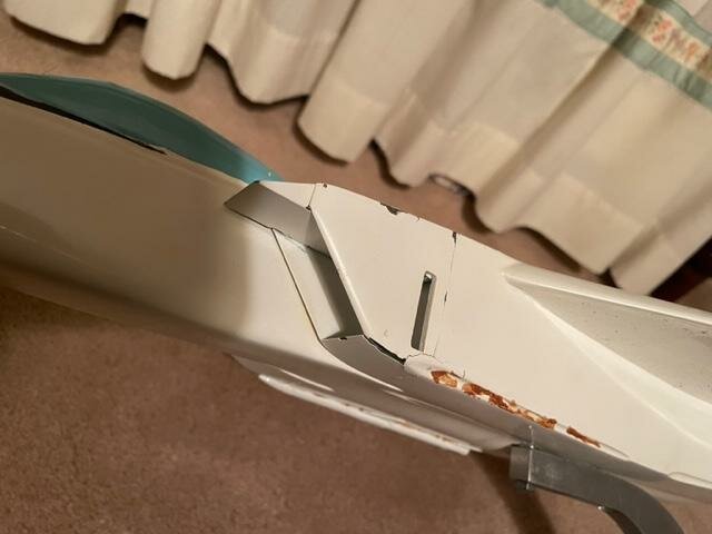
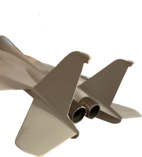
My thoughts on the opening:

The inlet side opening is clearly shown on the plans for model 199-1, meaning it is not just to display the ramp better.

It's not for flow straightening or preventing separation in the inlet from sideslip because the fuselage forebody does a good job of that (while blocking the leeward inlet).

It is forward of the throat, even at the maximum ramp angle (see the side view and section F-F in Figure 2-2 for model 199-1). That means the diffuser section of the inlet will be unaffected.

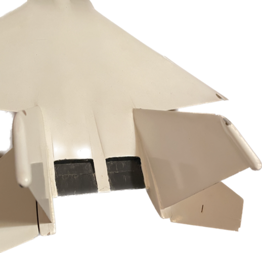
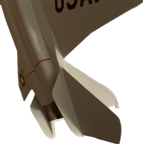
The forward edge of the opening is deflected outward (see the top view of Figure 2-2 for model 199-1).

My initial thought was for some kind of boundary layer removal, but I do not see a duct in the top view of Figure 2-2, even though there appears to be some kind of structure on the fuselage centerline side of the inlet shown in section F-F.

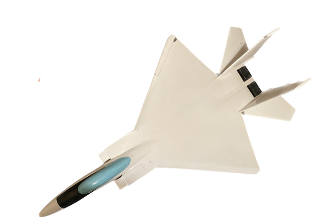
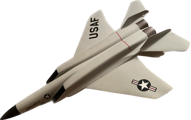
These inlets are quite interesting because they achieve variable capture area and inlet ramps with a single actuator. They also only have one very large ramp (unlike the multi-ramp design of the production F-15) which is somewhat counterbalanced by the hinge, allowing the actuator to be smaller.

Also note that some of the F-15 concepts have a very long, highly swept inlet with a prominent lower surface. This "opening" may be a way to have the same "effective" geometry as the design with the highly swept cowl lips. These inlets will have another shock form at the bottom surface because the flow is turned straight towards the inlet. In contrast, the production F-15's inlets do not have this lower surface. The lower lip is designed so the inlet area increases after the cowl lip.

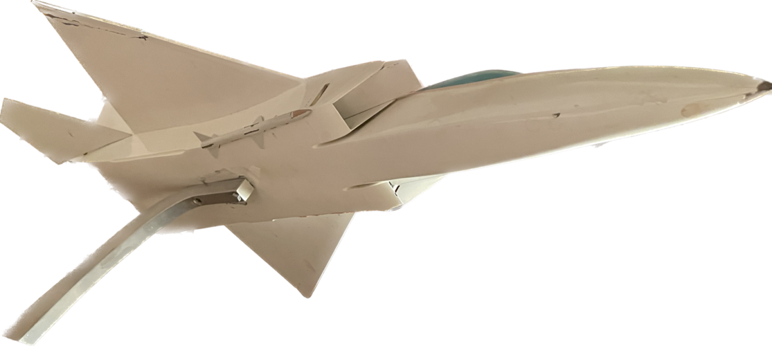
With all these in mind, I believe the hole is to make the inlet have similar flow characteristics to the type with the very highly swept lips to minimize any instability. I think the connection at the front is purely structural. It looks to be a brace to support the massive forces on the top and bottom of the inlet from the ramp and secondary compression surface (bottom) instead of having the bottom be mostly cantilevered.
 
No drawings. They are verbally described in F-15 PROPULSION SYSTEM DESIGN AND DEVELOPMENT (AIAA 75-1042); the same basic inlet but different ramp arrangements and fixed capture area/variable capture area.

Development Program for the F-15 Inlet (AIAA 74-1061) has detailed information on the actual inlet design and its features and benefits.
 

Attachments

  • 6.1975-1042 -- 0722c5a4034a13545554ccdd8d45fdde -- Anna’s Archive.pdf
    727.9 KB · Views: 35
I can see fences above the engine air intake.
"The high angle of attack problem arose as a result of adverse airflow characteristics in the vicinity of the vertical tails caused by the flow separation around the engine inlets and the inboard portions of the wings. The aft fuselage wide body prevented the airflow from recovering before reaching the tails."
 

Attachments

  • F-15 Eagle –Prelude to Flight (A Tall Tail Tale)_page-0006.jpg
    F-15 Eagle –Prelude to Flight (A Tall Tail Tale)_page-0006.jpg
    952.7 KB · Views: 63
  • F-15 Eagle –Prelude to Flight (A Tall Tail Tale).pdf
    1.3 MB · Views: 19

Similar threads

Back
Top Bottom