I Present the Tucker XP-57

GreatJimbo

ACCESS: Restricted
Joined
8 May 2019
Messages
21
Reaction score
89
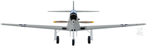
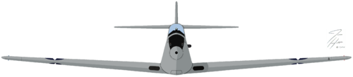
This is my latest profile. During my research the engine to be used was a "Straight Eight" so instead of the four exhaust ports on each side of the fuselage, I put all eight on the right side. I believe that all of the exhaust ports are on the same side of the engine, but I had to choose a side, so depending on which way the engine was to be installed, would determine which side the the ports would be on. So did I guess right? Probably not ;), but I went with it anyway. I did a right side profile to show the exhaust. Since the flying/landed top profiles are virtually the same I only did the one. I colored it as if had been sent to Wright Field for evaluation. Amazing enough when trying to find a serial number that I could use for it I found out that 41-004 had been reserved for the XP-57 by the USAAC!! I love the interwebs:D

Line drawing by Lloyd S. Jones

XP-57-color-side-landed-done.png XP-57-color-side-done.png XP-57-color-right-side-landed-done.png XP-57-color-right-side-done.png XP-57-color-front-landed-done.png XP-57-color-front-done.png XP-57-color-top-done.png
 
I recently made a 3d model of the XP-57 and put 4 exhaust ports on each side of the fuselage, but your reasoning has convinced me I should rework that and rather put 8 on the same side. Thanks for sharing!
 
I recently made a 3d model of the XP-57 and put 4 exhaust ports on each side of the fuselage, but your reasoning has convinced me I should rework that and rather put 8 on the same side. Thanks for sharing!

After talking with a member of a different forum, as well as a bit more research I found couple of photos of an original Miller front wheel drive racing motor sold at auction where the flywheel is facing forward, which would actually, in my opinion, mean all eight ports should be on the left side, or opposite of what I have done.

This is how I believe it should actually be:

XP-57-color-side-landed-done.png XP-57-color-right-side-landed-done.png

My question to everyone is should I update the pictures above with what I believe is correct, or just post the new ones and let whomever decide what they believe is correct?

Thanks!!
 
I recently made a 3d model of the XP-57 and put 4 exhaust ports on each side of the fuselage, but your reasoning has convinced me I should rework that and rather put 8 on the same side. Thanks for sharing!

After talking with a member of a different forum, as well as a bit more research I found couple of photos of an original Miller front wheel drive racing motor sold at auction where the flywheel is facing forward, which would actually, in my opinion, mean all eight ports should be on the left side, or opposite of what I have done.

This is how I believe it should actually be:

View attachment 636942View attachment 636944

My question to everyone is should I update the pictures above with what I believe is correct, or just post the new ones and let whomever decide what they believe is correct?

Thanks!!
The standard Miller inline engine layout was intake on the left side, exhaust on the right. When installed in a front-wheel drive chassis the engine was reversed. The L-510 of the
XP-57 was basically two 255 cu. in. four-cylinder engines joined end to end. The crankshafts were connected in the center and the power to the propeller driveshaft
was taken off that point, the shaft was to run beneath the engine. I’ve long wondered
where Lloyd Jones got his information as to how the aircraft was to look that he used
to create the drawing, I have doubts about the overall appearance.
 
The wing looks a lot with that of the P-38, isn't it (wing aspect ratio and tapering) ?
 
lot of similariy by eg PLZ 55 (?) and a few of the Super,marine design proposals
 

Similar threads

Back
Top Bottom