In January 1944 Daimler Benz built a twenty-four cylinders engine with 3,800 hp, called DB 613, formed by two DB 603 G engines coupled together to drive a single-shaft power with contra-rotating airscrews. But the set weighed two tons and was not useful to propel a VTOL aircraft.
In the last days of the World War Two, high power and reasonable weight was just a dream, piston engines weighed too much and jet engines had very little thrust.
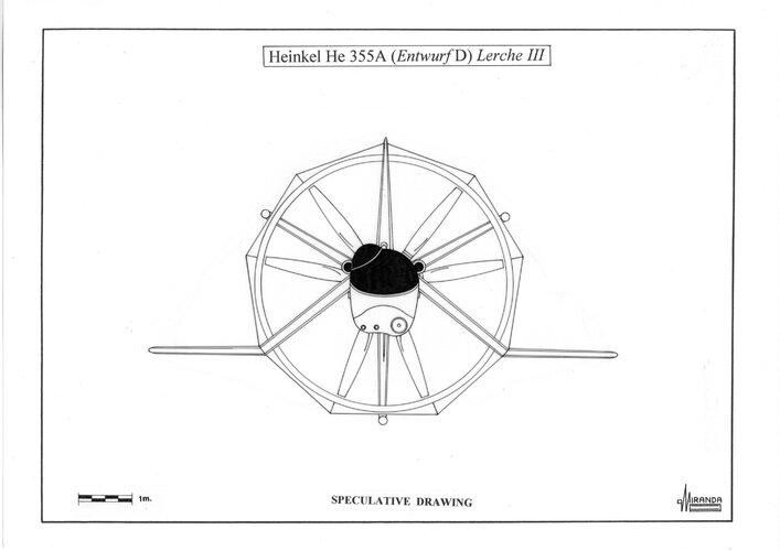
Lacking engines with sufficient power, Heinkel’s designers attempted to increase the efficiency by using ducted propellers, based on those of the Italian experimental aircraft Caproni Stipa, and annular wings based on the aerodynamic theories of Dipl.-Ing. Helmut Graf von Zborowski.
Inside an annular wing the tapered duct compressed the propeller’s airflow applying Benoulli’s principle. As the air forced into Venturi duct it accelerates.
Annular wings with ducted propellers were advantageous in augmenting engine thrust and in providing additional lifting area in forward flight. This means that a larger propeller with a greater pitch not require more engine power.
By incorporating adjustable control surfaces and varying the cross-section, the duct increases thrust efficiency by up 90 per cent in comparison to a similar-sized propeller in free-air.
It must be made rigid enough not to distort under flight, combat and landing loads.
A VTOL fighter needed that engine power to be delivered with rapid response even at the highest power levels.
The thrust needed to get off the ground had to exceed aircraft weight, but it was necessary for the power plant to provide additional thrust for maneuvering vertically.
A typical value for total thrust needed for vertical acceleration and maneuvering in the other axes would be about 1.7 times the aircraft maximum weight, on the contrary the thrust required in cruising flight would be only a fifth of aircraft weight.
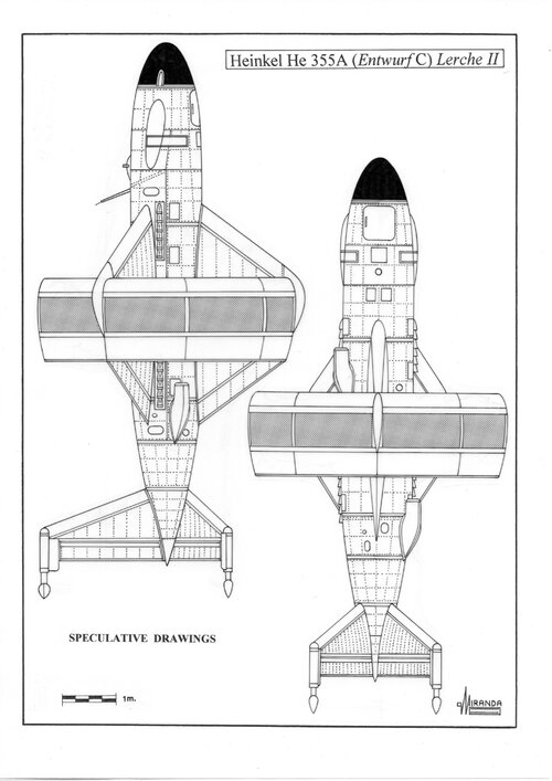
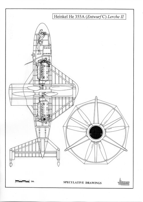
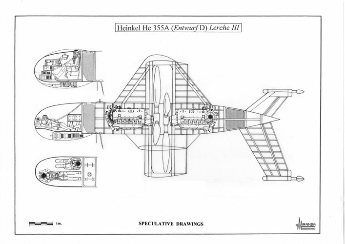
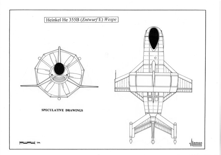
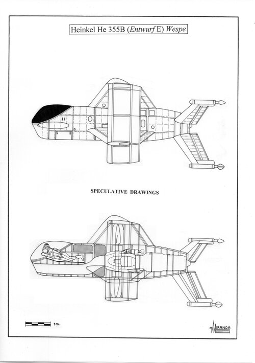
In December 1944, Dr.-Ing. Gerhard Schulze and Dipl.-Ing. Kurt Reiniger fron Heinkel-Wiener Neustädter Flugzeugwerke, designed two tilsitter fighters with annular wing called Heinkel He 355A Lerche and Heinkel He 355 B Wespe.
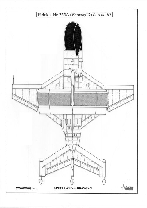
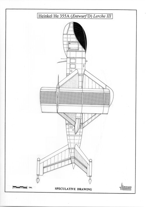
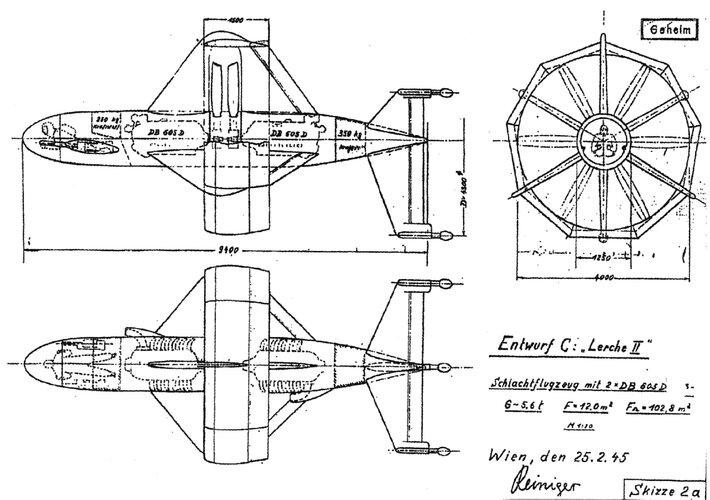
In February 1945, the VTOL project Lerche was proposed to the RLM in three different versions: Leuchter Jäger Lerche I (24.2.45), Schlachtflugzeug Lerche II (25.2.45) and Schwerer Jäger Lerche III (24.2.45).
Lerche I was a light fighter that weighed half as much as a Focke-Wulf Ta 152 C-3, it was powered by one Daimler-Benz DB 603 E and a six-blades ducted propeller with automatic-pitch control. This powerful engine generated a great deal of torque, to compensate this effect deflector vanes were mounted in the duct airstream.
Transition from over to forward flight was initiated by tilting the nose forward and gathering horizontal speed until wing lift took over.
There was a change in trim as the aircraft was rotated but control could be exercised by moving the vanes.
A sophisticated surface-cooling system developed for the high performance interceptor Heinkel project P. 1076, was integrated in the annular wing. The section between the spars housed the condensation tanks, the heat exchangers and the electric-driven pumps.
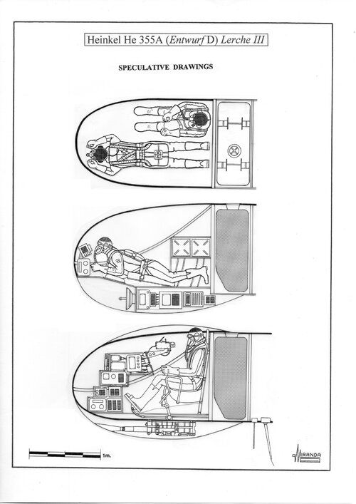
To avoid turbulence in the air stream produced by a protruding cockpit hood, it was necessary to design a fuselage of circular section based on that of the P. 1077 Julia project, with the pilot lying in prone position.
The automatic landing system was designed by Dipl.-Ing. Walter Hohbach.
In flight the three landing gear wheels were covered to save drag.
Heinkel He 355A (Entwurf A-B) Lerche I technical data
Ring wing diameter: 3.8 m, overall length: 7.75 m, rotor diameter: 3.3 m, wing area: 27 sq. m, surface area: 64.6 sq. m, wing chord: 2.79 m, estimated max weight: 2,500 kg, power plant: one DB 603E, twelve cylinder, inverted-Vee, liquid cooled engine with two-stage TKL 15 turbo-supercharger, rated at 1,810 hp in cruising flight and 2,250 hp at take-off with MW 50 booster, armament: two Mk 108/30 cannons mounted on each side of the fuselage with 3.5 degrees slope, electronics: EZ 42 gyroscopic gunsight, FuG 16 ZY R/T, FuG 25a IFF, FuG 125a radio-beacon, FuG radio-altimeter and Patin PKS auto-pilot.

")