According to
https://en.wikipedia.org/wiki/Heinkel_He_100
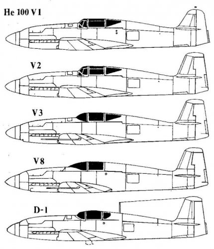
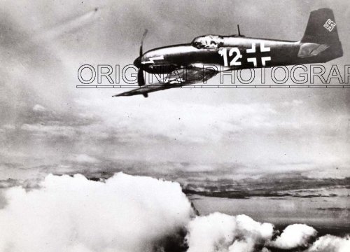
He100 V1
(1)The first prototype He 100 V1 flew on 22 January 1938.
(2)However, it continued to share a number of problems.
(a)Lack of directional stability.
(b)The Luftwaffe test pilots disliked the high wing loading, which resulted in landing speeds so great that they often had to use brakes right
up to the last 100 m (330 ft) of the runway.
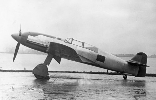
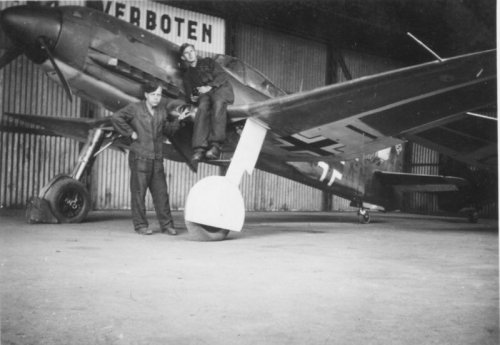
(c)The ground crews also disliked the design, complaining about the tight cowling which made servicing the engine difficult.
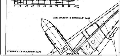
(d)The big problem turned out to be the cooling system.
He100 V2
(1)The second prototype He 100 V2 addressed the stability problems by changing the vertical stabilizer from a triangular form to a larger and more rectangular form.
(2)The oil-cooling system continued to be problematic., so it was removed and replaced with a small semi retractable radiator below the wing.
(3)It also received the still-experimental DB 601M engine which the aircraft was originally designed for. The M version was modified to run
on "C3" fuel at 100 octane, which would allow it to run at higher power ratings in the future.
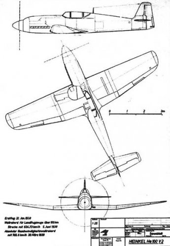
(4)V2 was completed in March
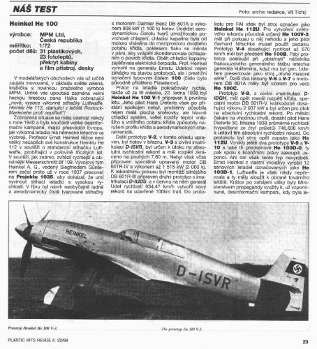
(5)Ernst Udet flew the V2 to a new world 100 km (62 mi) closed-circuit record on 5 June 1938, at 634.73 km/h (394.40 mph).
(6)The record was heavily publicized, but in the press the aircraft was referred to as the "He 112U". Apparently, the "U" stood for "Udet". At the
time the 112 was still in production and looking for customers, so this was one way to boost sales of the older design.
(7)V2 was then moved to Rechlin for continued testing. Later in October, the aircraft was damaged on landing when the tail wheel didn't
extend, and it is unclear if the damage was repaired.
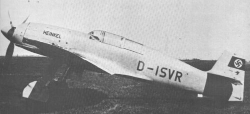
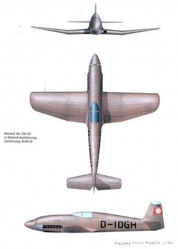
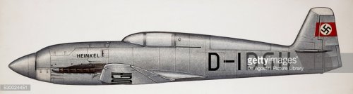
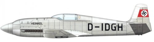
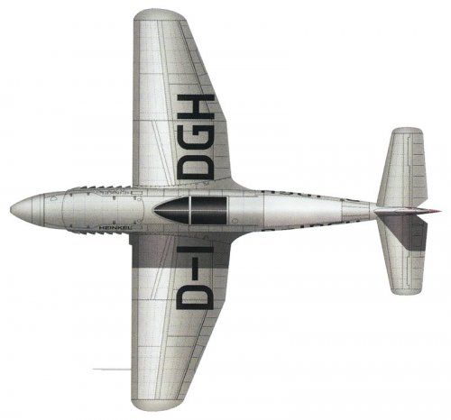
He100 V3
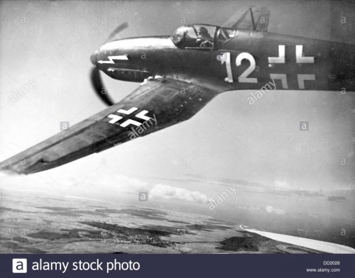
(1)The V3 prototype received the clipped racing wings, which reduced span and area from 9.40 m (30 ft 10 in) and 14.4 square metres (155 sq
ft), to 7.59 m (24 ft 11 in) and 11 m2 (120 sq ft).
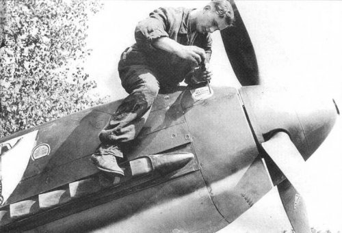
(2)The canopy was replaced with a much smaller and more rounded version, and all of the bumps and joints were puttied over and sanded
down.
(3)The aircraft was equipped with the 601M and flown at the factory.
(4)In August, the DB 601R engine arrived from Daimler-Benz and was installed. This version increased the maximum rpm from 2,200 to 3,000,
and added methyl alcohol to the fuel mixture to improve cooling in the supercharger and thus increase boost. As a result, the output was
boosted to 1,800 PS; 1,776 hp (1,324 kW), although it required constant maintenance and the fuel had to be drained completely after every
flight. The aircraft was then moved to Warnemünde for the record attempt in September.
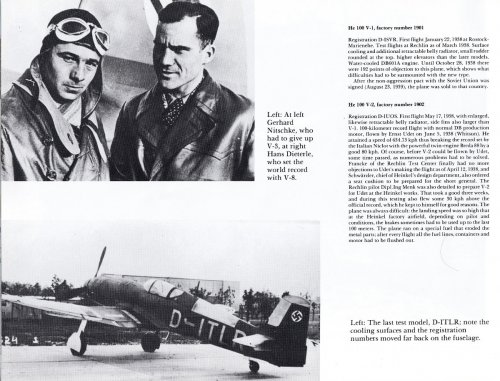
(5)On one of the pre-record test flights by the Heinkel chief pilot, Gerhard Nitschke, the main gear failed to extend and ended up stuck half
open. Since the aircraft could not be safely landed it was decided to have Nitschke bail out and let the aircraft crash in a safe spot on the
airfield. Gerhard was injured when he hit the tail on the way out, and made no further record attempts.
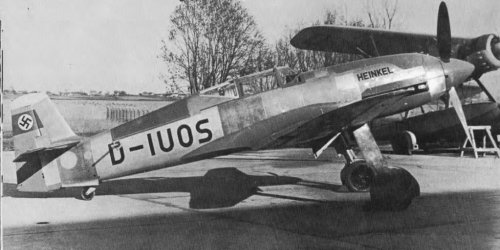
He100 V4
(1)V4 was to have been the only "production" prototype and was referred to as the "100B" model (V1 through V3 being "A" models).
(2)It was completed in the summer and delivered to Rechlin,
(3)in testing over the summer it proved to be considerably faster than the Bf 109. At sea level, the aircraft could reach 560 kilometres per hour
(350 mph), faster than the Bf 109E's speed at its best altitude. At 2,000 m (6,560 ft), it improved to 610 kilometres per hour (380 mph),
topping out at 669 km/h (416 mph) at 5,000 m (16,000 ft) before falling again to 641 km/h (398 mph) at 8,000 m (26,000 ft).
(4)The aircraft had flown a number of times before its landing gear collapsed while standing on the pad on 22 October. The aircraft was later
rebuilt and was flying by March 1939.
(5)Although V4 was to have been the last of the prototypes in the original plans, production was allowed to continue with a new series of six
aircraft.
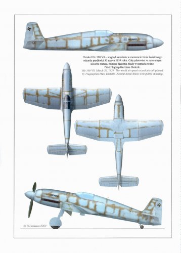
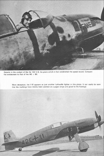
(6)One of the airframes was selected to replace V3, and as luck would have it V8 was at the "right point" in its construction and was completed
out of turn. It first flew on 1 December but this was with a standard DB 601Aa engine. The 601R was then put in the aircraft on 8 January
1939, and moved to a new course at Oranienberg. After several shakedown flights, Hans Dieterle flew to a new record on 30 March 1939, at
746.6 km/h (403.1 kn; 463.9 mph). Once again the aircraft was referred to as the He 112U in the press. It is unclear what happened to V8
in the end; it may have been used for crash testing.
He100 V5
(1)V5 was completed like V4, and first flew on 16 November.
(2)It was later used in a film about V8's record attempt, in order to protect the record breaking aircraft.
(3)At this point, a number of changes were made to the design resulting in the "100C" model, and with the exception of V8 the rest of the
prototypes were all delivered as the C standard.
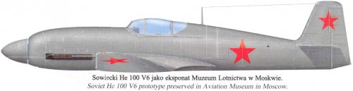
He100 V6
(1)V6 was first flown in February 1939, and after some test flights at the factory it was flown to Rechlin on 25 April.
(2)There it spent most of its time as an engine testbed. On 9 June, the gear failed inflight, but the pilot managed to land the aircraft with little
damage, and it was returned to flying condition in six days.
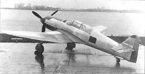
He100 V7
(1)V7 was completed on 24 May with a change to the oil cooling system.
(2)It was the first to be delivered with armament, consisting of two 20 millimetres (0.79 in) MG FF cannon in the wings and four 7.92 mm
(0.312 in) MG 17 machine guns arranged around the engine cowling. This made the He 100 the most heavily armed fighter of its day.
(3)V7 was then flown to Rechlin where the armament was removed and the aircraft was used for a series of high speed test flights.
He100 V9
(1) V9 was also completed and armed, but was used solely for crash testing and was "tested to destruction".
He100 V10
(1)V10 was originally to suffer a similar fate, but instead ended up being given the racing wings and canopy of the V8 and displayed in the German Museum in Munich as the record-setting "He 112U". It was later destroyed in a bombing attack.
Overheating problems and general failures with the cooling system motors continued to be a problem. Throughout the testing period, failures of the pumps ended flights early, although some of the test pilots simply started ignoring them. In March, Kleinemeyer wrote a memo to Ernst Heinkel about the continuing problems, stating that Schwärzler had asked to be put on the problem.
Another problem that was never cured during the prototype stage was a rash of landing gear problems. Although the wide-set gear should have eliminated the collapse of landing gears that plagued the Bf 109, especially in the difficult take-offs and landings, the He 100's landing gear was not built to withstand heavy use, and as a result they were no improvement over the Bf 109. V2, 3, 4 and 6 were all damaged to various degrees due to various gear failures, a full half of the prototypes.