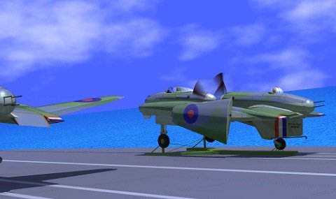
But what kind of advantages could have this special design??
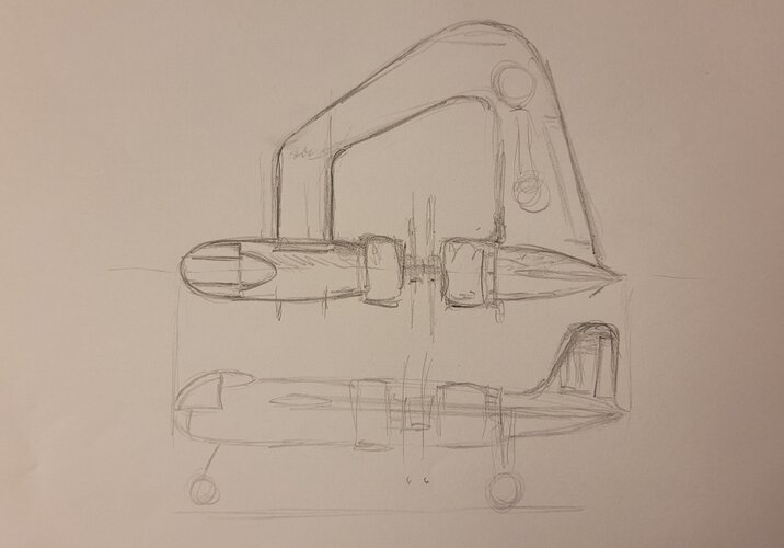
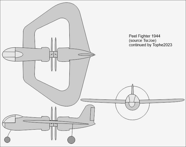
The configuration is one of the oddest I've ever seen.
Anyway thanks to Hesham for this special finding...
There are multiple advantages.
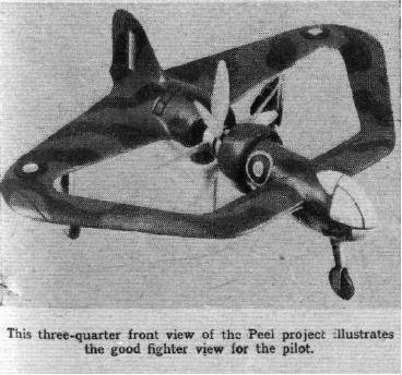
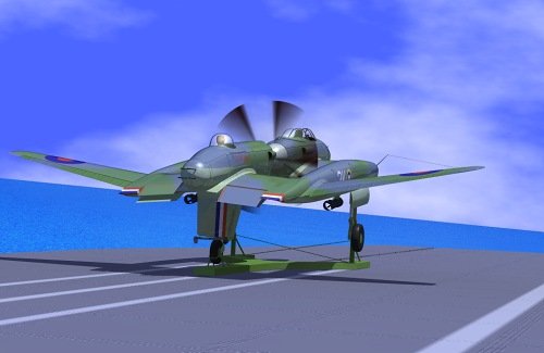
First, the pilot has great visibility.
Second, it can concentrate all guns in the nose ... simplifying alignment and aiming. Mounting heavy guns near the center-line increases roll rates.
Thirdly, it will balance better than most flying wings, tandem-wings and canards because heavy engines are near the center-of-gravity. That also allows for quicker pitch changes (versus Dornier 335 with props at the extreme ends of a long fuselage).
Fourthly, it balances engine weight without long drive shafts (Curtiss Ascender, Japanese Shiden, etc.).
Fifth, the rear prop is forward of the main wheels, eliminating the risk of prop strikes (on the runway) or the need for a tail bumper.
Sixth, the rudder is far enough aft (of the C. of G.) to provide meaningful stability and control.
Seventh, the rudder is a convenient place to hang an arrestor hook for carrier landings.
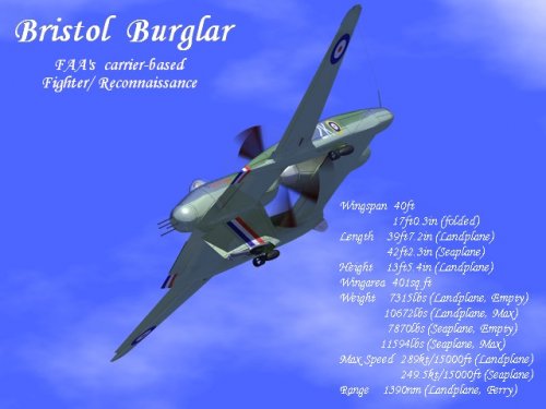
Eighth, the configuration is more of a tandem-wing or canard, specifically because the forward wing is smaller (narrower chord) than the rear wing. Both can provide lift. ... allowing the forward to wing to provide lift at high angles of attack. This would help with the STOL landings needed for deck landings. Consider that SAAB's Viggen and Grippen canards are among the few STOL jet fighters.
If you worry about the pilot bailing out past those spinning props, just bolt his seat to a lever arm (as suggested for Spitfire). The lever arm only has to be long enough to lift him above/below the prop arc.
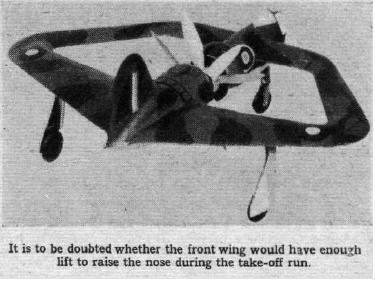
In conclusion, whether this airplane could be successful is a question of balancing extra structural weight versus all the advantages mentioned above.