EADS Hypersonic Transport

Triton

Donald McKelvy
Senior Member
Joined
14 August 2009
Messages
9,707
Reaction score
2,049
Website
deeptowild.blogspot.com
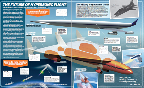
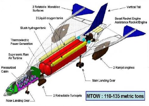
The study will assess the market and specifications for a hydrogen-fuelled, ramjet-powered, 60-passenger aircraft able to fly from Toyko to Los Angeles in 2hr 15min. It will also look at the trade-offs between single- and two-stage-to-destination vehicles.

Drawing of EADS Innovation Works and Astrium Space Transportation zero emission hypersonic transport.

Source:

Warwick, Graham. "Transpacific in Two Hours, With No Emissions" Leading Edge 5/28/2010
http://www.aviationweek.com/aw/blogs/aviation_week/on_space_and_technology/index.jsp?plckController=Blog&plckBlogPage=BlogViewPost&newspaperUserId=a68cb417-3364-4fbf-a9dd-4feda680ec9c&plckPostId=Blog%3aa68cb417-3364-4fbf-a9dd-4feda680ec9cPost%3af804340f-3ede-499c-8a0f-3f4e0a1b897f&plckScript=blogScript&plckElementId=blogDest
 

Attachments

  • 4c3cd496-0f9d-4b53-9981-e4e86cad9a8d.Full.jpg
    4c3cd496-0f9d-4b53-9981-e4e86cad9a8d.Full.jpg
    52.3 KB · Views: 462
Triton said:
The study will assess the market and specifications for a hydrogen-fuelled, ramjet-powered, 60-passenger aircraft able to fly from Toyko to Los Angeles in 2hr 15min. It will also look at the trade-offs between single- and two-stage-to-destination vehicles.

Drawing of EADS Innovation Works and Astrium Space Transportation zero emission hypersonic transport.

Except if it is H2 fueled, then it has water in the exhaust which is not zero emissions.
 
If it is Air + H2 then it has some NOx as well, and some other
molecules as well, I suspect, besides H2O.

Remember air is around 98% O2 + N2.
 
shockonlip said:
If it is Air + H2 then it has some NOx as well, and some other
molecules as well, I suspect, besides H2O.

Remember air is around 98% O2 + N2.

Yes, 78.084% N2 and 20.947% O2. Plus 0.934% Ar and 0.033% CO2. The remaining 0.002% being trace amounts of other gases.
 
was thinking the same...

a rocket with turbojets with ramjets...

large bulge in the middle :-\

then winglets...

good luck with that
 
...and how do you obtain your hydrogen without causing any carbon emissions?, (as if CO2 was really a problem ;D) 'cause there ain't none in the atmosphere and separating it from water takes more energy than you get back - blah blah blah...

Cheers, Woody
 
shockonlip said:
If it is Air + H2 then it has some NOx as well, and some other
molecules as well, I suspect, besides H2O.

Remember air is around 98% O2 + N2.

Not really expected at the temps the engines will run at. For reference see the Mach 7.5 DCSCTF equilibrium concentrations, http://hapb-www.larc.nasa.gov/Public/Facilities/Dcsctf/table_2.gif NO is just 0.4%. Admittedly, this temp is a bit low for a ramjet, but the concentration is not going double for temps below where you begin to have issues with the H2O not completely forming in the combustion products as then the engine thrust and efficiency goes to hell in a hand basket.
 
I don't get the 'transport' part...
It is another concorde-replacement idea.. Supersonic transport for a few very rich people. I find it uneconomical, no airline-company is going to consider this idea. Such a big plane for only 60 people? Never going to get of the ground..
 
Orionblamblam said:
It seems an excessively "busy" design. If you are travelling hypersonically, you really want your geometry to be as simple as possible
Oh, agreed. This design looks like a nonstarter, especially with those podded engines and their interference effects with the wings (shock-shock interactions and shock impingement effects are a truly epic can of worms to deal with up past Mach 3ish). The winglets in the back look like they could be a SpaceShipOne-type feathering system, but it needs way more vertical stabilizer on them. The huge hydrogen tanks dominating the fuselage kill the whole idea dead anyway. Way too few passengers for a vehicle that size, for one.

I for one believe there are better ways to store hydrogen than just cryogenic slush anyway.
 
dannydale said:
Oh, agreed. This design looks like a nonstarter, especially with those podded engines and their interference effects with the wings (shock-shock interactions and shock impingement effects are a truly epic can of worms to deal with up past Mach 3ish).
I for one believe there are better ways to store hydrogen than just cryogenic slush anyway.

The big thing about podded engines is the cowl drag. This was seen in the NASA HRE (Hypersonic Research Engine) program.
http://hapb-www.larc.nasa.gov/Public/Engines/Hre/Hre.html. Net thrust was not positive.

What way do you propose to store H2? If you don't go cryo/slush then how to you make up the heat sink?
 
DSE said:
shockonlip said:
If it is Air + H2 then it has some NOx as well, and some other
molecules as well, I suspect, besides H2O.

Remember air is around 98% O2 + N2.

Not really expected at the temps the engines will run at. For reference see the Mach 7.5 DCSCTF equilibrium concentrations, NO is just 0.4%. Admittedly, this temp is a bit low for a ramjet, but the concentration is not going double for temps below where you begin to have issues with the H2O not completely forming in the combustion products as then the engine thrust and efficiency goes to hell in a hand basket.

Reference DSE?

Thanks.
 
DSE said:
dannydale said:
Oh, agreed. This design looks like a nonstarter, especially with those podded engines and their interference effects with the wings (shock-shock interactions and shock impingement effects are a truly epic can of worms to deal with up past Mach 3ish).
...

The big thing about podded engines is the cowl drag. This was seen in the NASA HRE (Hypersonic Research Engine) program.
http://hapb-www.larc.nasa.gov/Public/Engines/Hre/Hre.html. Net thrust was not positive.
...

dannydale's reference of the shock/BL interactions on the X-15 HRE were certainly the most publicized
as they caused the podded scramjet to burn off the pylon and the X-15A-2 was almost destroyed!
Pete Knight REALLY earned his pay on that flight. He couldn't dump fuel either so the chase A/C could
find him as the heat had entered the airframe through the holes in the Inconel X caused by the shock/BL
interactions, and the heat screwed up the dump mechanism, as well as other things, so he also landed
heavy and fast on his own. As I recall, when he popped the canopy he was expecting them to run up to him
and help him out of the cockpit, but everyone ran right by and was looking at the damage at the aft
end of his X-15.. They later came up and apologized for letting him fly, saying they had no idea.
It was a famous flight. Non-podded, integrated ramjets/scramjets became the order of the day.
 
shockonlip said:
dannydale's reference of the shock/BL interactions on the X-15 HRE were certainly the most publicized
as they caused the podded scramjet to burn off the pylon and the X-15A-2 was almost destroyed!
Pete Knight REALLY earned his pay on that flight. He couldn't dump fuel either so the chase A/C could
find him as the heat had entered the airframe through the holes in the Inconel X caused by the shock/BL
interactions, and the heat screwed up the dump mechanism, as well as other things, so he also landed
heavy and fast on his own. As I recall, when he popped the canopy he was expecting them to run up to him
and help him out of the cockpit, but everyone ran right by and was looking at the damage at the aft
end of his X-15.. They later came up and apologized for letting him fly, saying they had no idea.
It was a famous flight. Non-podded, integrated ramjets/scramjets became the order of the day.

Yes, it was a really big SNAFU with the flight and it was amazing the vehicle was not lost. Note a copy of that NASA TM is available off the HRE page I referenced. Howeve,r my point is that even if this had not been an issue, in the end the HRE would not produce net thrust. Kind of a non-starter for a real engine, no? HRE was only an internal performance demonstration project. One of the first references published regarding airframe-integrated scramets was Design Considerations for the Airframe-Integrated Scramjet, Henry, J. R. and Anderson, G. Y., NASA TM X-2895, December, 1973, http://hapb-www.larc.nasa.gov/Public/Documents/nasa_tm_x-2895.pdf

I might also point out that someone must have had some thoughts with regard to the strut the dummy HRE was going to hang off of as a wind tunnel model was used which had a highly swept strut. See Study of underexpanded exhaust jets of an X-15 airplane model and attached ramjet engine simulator at Mach 6.86, Andrews, E. H., Jr.; Rogers, R. C., NASA-TM-X-1571, May 1, 1968. http://hdl.handle.net/2060/19680015142
 
DSE said:
shockonlip said:
dannydale's reference of the shock/BL interactions on the X-15 HRE were certainly the most publicized
as they caused the podded scramjet to burn off the pylon and the X-15A-2 was almost destroyed!
Pete Knight REALLY earned his pay on that flight. He couldn't dump fuel either so the chase A/C could
find him as the heat had entered the airframe through the holes in the Inconel X caused by the shock/BL
interactions, and the heat screwed up the dump mechanism, as well as other things, so he also landed
heavy and fast on his own. As I recall, when he popped the canopy he was expecting them to run up to him
and help him out of the cockpit, but everyone ran right by and was looking at the damage at the aft
end of his X-15.. They later came up and apologized for letting him fly, saying they had no idea.
It was a famous flight. Non-podded, integrated ramjets/scramjets became the order of the day.

Yes, it was a really big SNAFU with the flight and it was amazing the vehicle was not lost. Note a copy of that NASA TM is available off the HRE page I referenced. Howeve,r my point is that even if this had not been an issue, in the end the HRE would not produce net thrust. Kind of a non-starter for a real engine, no? HRE was only an internal performance demonstration project. One of the first references published regarding airframe-integrated scramets was Design Considerations for the Airframe-Integrated Scramjet, Henry, J. R. and Anderson, G. Y., NASA TM X-2895, December, 1973, http://hapb-www.larc.nasa.gov/Public/Documents/nasa_tm_x-2895.pdf

I might also point out that someone must have had some thoughts with regard to the strut the dummy HRE was going to hang off of as a wind tunnel model was used which had a highly swept strut. See Study of underexpanded exhaust jets of an X-15 airplane model and attached ramjet engine simulator at Mach 6.86, Andrews, E. H., Jr.; Rogers, R. C., NASA-TM-X-1571, May 1, 1968. http://hdl.handle.net/2060/19680015142

Understood about the cowl drag.

But it seems the HRE was largely successful actually per
Fig. 11 of AIAA 93-2323 (and skimming the rest of the paper).

They pretty well hit the lower target performance curve
pictured in Fig 11.

Seeing Ct >= 1 in Figure 11 on the lower performance curve
for M4-5, and Ct < 1 for 5 < M <= 8. They never mentioned cowl
drag as the reason.

The upper performance curve was supposed to be for Mach No.
optimized engines, but it had Ct > 1 in the Mach 4-6 range
but Ct < 1 for 6 < M <= 8.

So it looks like the performance was planned (no surprise
there) and they wanted to predict it ahead of time. It actually
looks like they knew what they were doing!

Pretty amazing program actually !

And I posted earlier that: "the shock/BL interactions on the
X-15 HRE were certainly the most publicized" as most of us were
not privy to the post 1968 HRE tests (after X-15 was cancelled)
until 1993 or so when that AIAA paper was published. And the
shock/BL interactions were really cool! I was blown away when I
first heard about them!

Also thanks for the Ref on the Underexpanded Exhaust Jets paper
and the interesting ventral/scramjet config.

I have an idea I have to check out now!

Regards.
 
shockonlip said:
Understood about the cowl drag.

But it seems the HRE was largely successful actually per
Fig. 11 of AIAA 93-2323 (and skimming the rest of the paper).

They pretty well hit the lower target performance curve
pictured in Fig 11.

Seeing Ct >= 1 in Figure 11 on the lower performance curve
for M4-5, and Ct < 1 for 5 < M <= 8. They never mentioned cowl
drag as the reason.

Not to harp on this, but it seems you've missed the point. Figure 11 is INTERNAL performance. This does not include the external cowl drag. See the real issue now, if the CT <1 without including external drag?


So it looks like the performance was planned (no surprise
there) and they wanted to predict it ahead of time. It actually
looks like they knew what they were doing!

Pretty amazing program actually !

Yes, the real goal of all these programs is can you predict the performance. They did this for the internal scramjet performance on HRE. Hyper-X took it to another level, predicting total vehicle performance (acceleration) within the uncertainty of prediction. The accelerometer requirements were driven by the need to measure performance to better than the predicted uncertainty level.
 
DSE said:
shockonlip said:
Understood about the cowl drag.

But it seems the HRE was largely successful actually per
Fig. 11 of AIAA 93-2323 (and skimming the rest of the paper).

They pretty well hit the lower target performance curve
pictured in Fig 11.

Seeing Ct >= 1 in Figure 11 on the lower performance curve
for M4-5, and Ct < 1 for 5 < M <= 8. They never mentioned cowl
drag as the reason.

Not to harp on this, but it seems you've missed the point.
Figure 11 is INTERNAL performance. This does not include the
external cowl drag. See the real issue now, if the CT <1 without including external drag?

I realize it can be frustrating.
People always have reasons for drawing conclusions.
You shouldn't assume they've "missed the point".
They may have unresolved questions.

In my case. The paper was full of references to the phrase
"internal performance". Fair enough.

But in my case, I am an enginner too, and if I don't understand,
I don't accept what the paper is saying, or I am skeptical of
both my understanding as well as the paper, until I can resolve
the problem.

What I am not getting is how can they seperate external
performance from internal performance?

Now remember, I am learning this ALL, on my own. I don't
have an AE instructor, nor do I have anyone I know who has
worked in the industry accessible for an easy conversation.
I read these textbooks and derive the equations and work
the problems and resolve my problems on my own. And I am
gonna work on this shit someday! So getting back to the gist.

The pictures on the HRE website show a picture of
HRE AIM mounted in the Lewis/Plumbrook Hypersonic Tunnel Facility,
looking upstream into the facilities hypersonic nozzle. From the
size of the nozzle, it looks as though, what the AIAA paper calls
the "outerbody" (which consists of the cowl leading edge, the
outer shell, and the nozzle shroud - This all was also a little
later called the "outer cowl" I believe), would be definitely
immersed in the hypersonic flow coming out of that facility
nozzle.

So again, I ask myself, how are they seperating external performance
from internal performance because all these external "parts" are
within the flow.

So based on your goading, I have had another look, and I think
I now understand.

The paper talks about a "hard point beam" without showing it in
Figure 7. To me that initially didn't mean very much as I couldn't
see where it was. I now beieve (but am not completely sure, but feeling
much more confident) that "hard point beam" and what is connected to
it is at rest. In other words, is not part of the thrust/drag
measurement. It eventually helped when they said that the engine
"outer cowl" (ie: "outer body") and main mount strut aero covers were
mounted to the "hard point" (I assume they mean the "hard point beam").

Anyway if the above is true, then it makes sense, the "outerbody"
or "outer cowl" and the aero covers of the main mount, are definitely
within the hypersonic flow, but are not part of the thrust/drag
measurement!

It seems though that the main mount's internal load beam must be
allowed to move within its aero cover (the aero cover itself is at
rest mounted to the "hard point beam" - the aero cover is pretty
wide, and looks like there may be plenty of room for the main beam
itself (the load carrying member) to move fore/aft within the aero cover).

The paper is very good, but it lacks in a better explanation of this
question accessible to amateurs like me.

So the above is my attempted resolution of my problem.

Do you think I have figured it out?

If not, maybe we should take it offline if you have the time.
 
shockonlip said:
In my case. The paper was full of references to the phrase
"internal performance". Fair enough.

But in my case, I am an enginner too, and if I don't understand,
I don't accept what the paper is saying, or I am skeptical of
both my understanding as well as the paper, until I can resolve
the problem.

What I am not getting is how can they separate external
performance from internal performance?

You need to think about a control volume analysis of the flow through the engine and the force accounting which goes with that. See for instance http://www.cs.odu.edu/~mln/ltrs-pdfs/NASA-97-agard-jlh.pdf for the various force accounting methods which can be used. Next you need to understand a typical measurement made in propulsion tests, deltaF, which is the measured change in axial force between fuel off and fuel on conditions. Note that this is extended to all forces and moments. The measured deltaF can be related to the net internal force or thrust of the flowpath/control volume. The difference between the the net internal force or thrust and deltaF is the internal non-fueled drag. The very large assumption here being the external drag and the forebody/inlet drag does not change between the two measured states, fuel on/off. Which for most cases is a reasonable assumption, but pressure measurements are used on the applicable surfaces to justify or correct for this. So the unfueled flowpath data is used to estimate the internal drag of the engine. It is assumed the fueled drag is not very different and so this estimate of the internal drag is subtracted from the measured deltaF to get the net internal thrust. See Methods for Determining the Internal Thrust of Scramjet Engine Modules from Experimental Data, http://hapb-www.larc.nasa.gov/Public/Engines/Parametric_engine/larc_parametric.html

The key here is that the measured force includes all the external and support surfaces, however, by looking at the change in force, these are then subtracted out.

Hope this is helpful.
 
shockonlip said:
If not, maybe we should take it offline if you have the time.
Don't take it offline, as I'm thoroughly enjoying the discussion.
 
The Lockheed X-7's podded ramjet worked just fine up to mach 4.3 (though it was mounted much nearer the aircraft's centre line).

I guess you're talking about much higher numbers but what kind of speeds would this EADS Hypersonic Transport need to reach to carry out it's suborbital flight profile?

http://www.456fis.org/LOCKHEED_X-7.htm

Cheers, Woody
 

Attachments

  • x7a3_03[1].jpg
    x7a3_03[1].jpg
    33.4 KB · Views: 334
From How It Works magazine.
 

Attachments

  • 1.png
    1.png
    924.5 KB · Views: 238

Similar threads

Back
Top Bottom