- Joined
- 25 June 2009
- Messages
- 13,745
- Reaction score
- 2,930

On January 23, 1958, the staff at the NACA Langley Aeronautical Laboratory entertained a visitor, a practicing physician from the small town of Neponset, Illinois. His name was William R. Bertelsen, and he had brought with him a small, powered model of a radical deflected-slipstream VTOL, called the “Arcopter” because of its arc-shaped wing. On hand that day were many luminaries of that era’s of aeronautical research: Richard Kuhn, John Draper, Kenneth Spreeman, Frances Rogallo, Charles Zimmerman, Robert T. Taylor, and others. Dr. Bertelsen hoped that his Arcopter concept might be included in the ongoing wind tunnel studies of various deflected slipstream prototypes. He started the glo-plug engine and flew the model, demonstrating its ability to hover out of ground effect. He made the model translate forwards and backwards, manipulating a canard vane by means of a slender piano wire. To place this event in the context of the times, the Arcopter demonstration at Langley took place three months after the launch of Sputnik (October 4, 1957), and less than one month before the rollout of the Ryan VZ-3RY Vertiplane in California (February 7, 1958). The first flight of the VZ-3RY at Moffett Field was still a year away (January 21, 1959).
The group at Langley was largely impressed with the Arcopter, but they also made it clear that the near-term chances for a study at Langley were zero. Langley Aeronautical Laboratory was about to become NASA Langley Research Center, only ten months hence, on October 1, 1958. Funding for aeronautics was being reduced to a trickle as the space program became an overnight leviathan. A photo of the inventor and the model that was flown for NASA Langley appears in Figure 24 below.
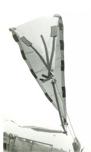
The Arcopter is distinctive because of its unique wing and flap geometry. Dr. Bertelsen reasoned that the arc shape should be the most efficient configuration for turning the circular slipstream of a propeller. It minimized the wing surface area, thereby also minimizing losses due to skin-friction drag in hover. The flaps were permanently extended on the proof-of-concept model. On a full-scale aircraft, they could rotate clockwise to retract into the main arc wing during transition to high-speed cruise.
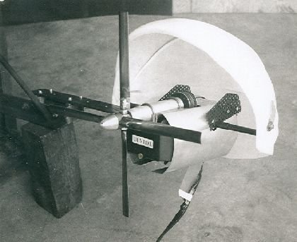
The model’s wings were made of molded acrylic plastic. Span was 12 inches and the diameter of the propeller was 14 inches. Power was from a rear-mounted “Torpedo 35” glo-plug model engine [Fig. 25].
The aluminum landing legs doubled as handles for sensing forces and moments. Note the canard control surfaces for pitch, yaw, and roll control just behind the propeller in Figure 25 above. Since the canards were always bathed in the slipstream of the propeller, they
remained effective in hover [Fig. 26].
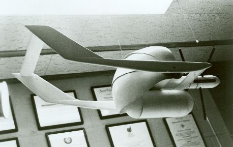
Locating the engine in the rear balanced the model perfectly so that the arc wing did all the heavy lifting. The horizontal canard planes were basically unloaded, except for simply pointing the nose up or down. The canards also served to reduce the torque generated by the large propeller, although they did not eliminate it completely. Plans for a full-size prototype call for a dual-rotating, controllable-pitch propeller to eliminate torque and augment roll control with differential pitch [Fig. 27].
The Arcopter configuration takes advantage of a large-diameter propeller (14 feet) for maximum efficiency and features centerline thrust. No cyclic pitch mechanism is required. The twin engines could be modified automotive piston engines to minimize cost. However, the most important aspect of the Arcopter system is the force focus, which directly addresses the pitching moment problems that plagued the VZ planes, i.e., the Ryan Vertiplane and the Fairchild Fledgling.
Dr. Bertelsen had studied the works of Richard Kuhn, John Draper, Kenneth Spreeman, et al, on large-chord slotted flaps (references 1 and 7) from 1955 and 1956. He was well aware of the trim problems associated with the deflected slipstream approach that these NACA researchers documented during exhaustive trials in the Langley wind tunnel. To minimize the trim problem, Dr. Bertelsen lowered the center of gravity and mandated a radial flap extension path [Fig. 28].
It can be seen that the radial deployment of the flaps keeps the individual flap resultant force vectors focused through the center of gravity during all stages of extension and retraction. Therefore the vector sum of the thrust and wing/flap vectors is a vertical lift force that continuously coincides with the center of gravity. For pilots it means that the aircraft will remain in trim, with a zero pitching moment as the flaps are extended and retracted. As a bonus, there is static angle-of-attack pitch stability, even at very low forward speeds (unlike the VZ planes). This beneficial focus of forces is referred to as the “Bertelsen Effect” in the original U.S. patent #3,597,614, filed in 1961.
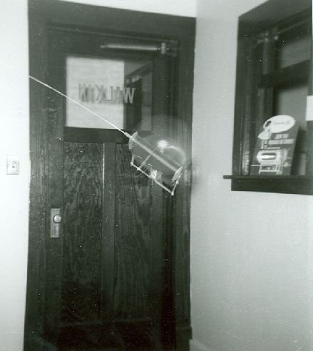
The Langley Arcopter demonstrator model was not the first Arcopter to lift its own weight. A smaller model with wings and control surfaces fashioned from X-ray film flew in 1957 [Fig. 29]. This model was powered by a Cox “Thimble Drome” 049 glo-plug engine. Fig. 30 below is a photograph of the model flying in the waiting room of Dr. Bertelsen’s medical office.
While flying the glo-plug models, Dr. Bertelsen found that the turning angle of the slipstream was reduced somewhat when descending into ground effect. However, unlike the VZ planes, the Arcopter seemed to be able to lift more weight in ground effect rather than less. He realized that there was a potential for a new class of aircraft designed to operate in ground effect full-time, lifting big payloads with minimal installed power. When it became clear that no NACA support for Arcopter development was forthcoming, Dr. Bertelsen shelved the Arcopter idea and began his alternate career as a pioneer of ground-effect machines, otherwise known as air cushion vehicles or hovercraft.
[continued below]
Attachments
-
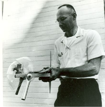 Figure 24—Dr. William R. Bertelsen with the Arcopter Proof-of-Concept Model in 1958.jpg28.1 KB · Views: 232
 -
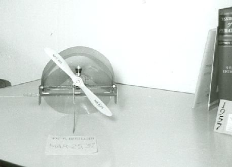 Figure 29—Earliest Arcopter Flying Model, March 25, 1957.jpg15.3 KB · Views: 22
 -
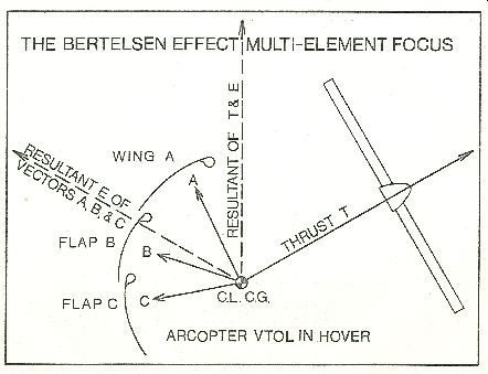 Figure 28—Force Focus of Arcopter VTOL System.jpg25.9 KB · Views: 207
 -
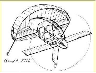 Figure 27—Twin-Engine, Four-Place Arcopter VTOL Concept, Flaps Down.jpg22.8 KB · Views: 214
 -
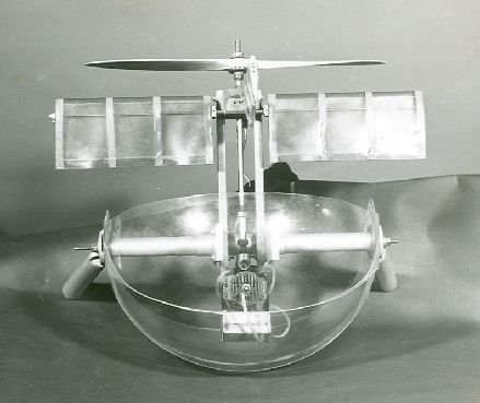 Figure 26—Arcopter Model, Plan View.jpg23.9 KB · Views: 219
 -
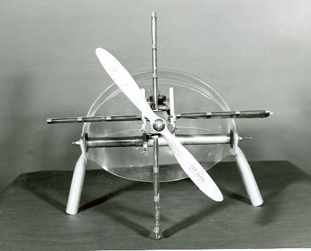 Figure 25—Arcopter Model, Front View, Flaps Down.jpg21.2 KB · Views: 228