- Joined
- 18 May 2019
- Messages
- 636
- Reaction score
- 1,570

COMBINED ARMS MULTIPURPOSE MISSILE
Combined Arms Multipurpose Missile (CAMM) is a Missile Command research and development program being conducted inhouse with industry support to demonstrate an innovative missile guidance concept offering major performance improvements for anti-air weapon system applications.
A multiguidance concept is being developed to extend the use of terminal homing seekers against long range, low signature targets in clutter by combining the features of terminal homing and command guidance into a single, lightweight missile for multipurpose roles.
Three modes of operation would be available to cover a wide variety of target and conditions; a lock-on before launch fire-and-forget mode always used when the target signature to clutter ratio permits, a line-of-sight command guidance mode used when this ratio is low and target lock-on is not possible or in severe countermeasure environments, and finally, a lock-on-after-launch mode that uses command guidance early to guide the missile and point the seeker towards the target to enable the earliest possible target lock-on-after-launch for moderate signature/clutter conditions. The flight demonstration of this. third mode is the primary objective of this program. The other two modes separately are well within current technology capability.
Begun in 1988 with the selection of the HELLFIRE missile as a test bed, the program is nearing the completion of hardware development. Static, captive, and missile environment testing is in progress. Flight tests are planned in 1991-92. Design details will be given.
INTRODUCTION
Combined Arms Multipurpose Missile (CAYM) is a MICOM 6.2 funded technology demonstration program that combines fire-and-forget terminal homing seeker guidance with command guidance on the same missile to achieve a major performance improvement in missile guidance capability. In this case sophisticated target acquisition and guidance hardware is carried on board the missile to achieve higher terminal accuracy at longer range than can be obtained with command or terminal homing guidance alone.
The CAMM program is aimed at demonstrating the availability and maturity of technology to implement this dual guidance concept to allow missiles to operate more effectively at longer ranges.
OBJECTIVE
Previously, the Army Missile Command has developed lock-on-beforelaunch (LOBL) seeker technology for its fire-and-forget capability, but with the missile operating range limited to the lock-on range capability of the seeker. Now, with technology advances, the missile range can be extended by flying part of the way with command guidance until the seeker and its processor can lock onto the target and complete the engagement in the terminal homing mode. Demonstration of this lock-on-after-launch (LOAL) capability required to implement a dual guidance concept is the key objective of the CAMM program.
APPLICATIONS
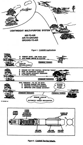
The CAMM concept, as depicted in Figure 1, has application to a wide variety of lightweight launch platforms and targets, hence the term "multipurpose."
Included in the launch platforms are the future light helicopter (LRiX) for the aviation role and a Pedestal Mounted Stinger type of light vehicle platform for the air defense role. The target set includes both air and ground targets. The most difficult target from a seeker lock-on standpoint is the long range helicopter hovering in clutter. The armored target is the most difficult from a warhead viewpoint. Both of these tend to increase missile diameter. The maneuvering fixed wing target drives the missile kinematics which leads to a larger length-of-diameter ratio or longer missile.
The CAMM program is focusing on the first problem of engaging long range, low signature targets in clutter. To this end the innovative dual guidance concept based on the most advanced seeker and image processor technology is being developed. Its objective is to demonstrate a means to rapidly engage any line-of-sight target detected by the platform fire control sensor suite, even when the target signature to clutter ratio is too low to permit LOBL.
Flight demonstrations of this technology and concept are planned using the HELLFIRE missile as a test bed. The issues of warhead sizing, airframe kinematics and platform sensor suite development will be left for a future weapon system development program such as The Army Counter Air Weapon System (TACAWS).
DUAL GUIDANCE
Dual guidance extends the operating range and application of the host missile by adding the capabilities of the two guidance modes. The mid-course command guidance will be accomplished by C02 laser beamrider due to availability of hardware. Millimeter wave command guidance is another candidate approach for this function. Terminal homing guidance will be implemented initially using TV seekers as surrogates for the more tactically suitable Imaging Infrared (fIR) seekers. Actual flights with IIR seekers are planned for later after proving out the test bed missile with the lower cost TV seeker.
As illustrated in Figure 2, three distinct operating modes are available. with the dual guidance concept. The classical lock-on-before-launch, true fire and-forget mode is available and would always be used when the target signature, clutter and countermeasures environment allow. The lock-on range and use of this mode can be severely restricted by these conditions. The command guidance mode all the way to intercept is available for adverse conditions when signature, clutter or countermeasures does not allow target lock-on by the seeker. In this mode the missile is tethered to the platform for guidance and its long range accuracy is limited.
By combining the two guidance modes on a single missile, as shown at the bottom of the figure, a third mode which extends the missile operating range and performance is possible. A target "filter" is obtained from the platform's computer library of target optical images and is loaded into the missile seeker before launch. This tells the missile seeker what target to look for within its narrow field-of-view. It is based on all of the information known about the target from the platform's sophisticated sensor suite or from external inputs.
The seeker is pointed toward the target while the missile is flown by command guidance toward the target. When the Automatic Target Recognition (ATR) processor is able to establish a correlation between the stored target filter and the seeeker provided video, which includes target and clutter, handover occurs to the seeker target tracker and the engagement is completed in the terminal homing mode. The target filter may also be used for terminal aimpoint selection to provide information to the tracker to obtain the most effective aimpoint for each target.
It is this third mode of operation that is the technology challenge of the CAMMS program and for which hardware is being developed for proof-ofprincipal flight demonstrations. The first two modes are considered to be well within current capability.
An additional capability is being investigated in which the seeker video also would be transmitted back to the platform to permit operator input and trajectory adjustment. Implementation of this could be by means of a modulated laser retro-reflector in the aft of the missile. The command guidance approach chosen for CAMMS is a C02 laser beamrider raster scan implementation, shown in Figure 3. The center of the scan is placed on the line-of-sight (LOS) to the target by virtue of its being boresighted to the TV or FLIR target tracking sensor. The time of arrival of the laser beam on the missile receiver is unique for each position within theraster. The missile is thus able to determine it position and maintain itselfon the LOS to the target.
A simplified version of the ATR processor is shown in Figure 4. The target filter consists of a 256 X 256 X 8 bit array of numbers representing the target image in the frequency domain for every 10 degrees of target aspect. Several target filters are required for target growth to cover band of range-to-go. A corresponding array is developed in real time during flight from the seeker image using a two-dimensional FFT processor. The 256 X 256 array and a 2.2 degree field-of-view produce an instantaneous field-of-view of 150 microradians. This results in 10 pixels within a 3.0 meter dimension of a target at a range-to-go of 2.0 kilometers. This is the CAMN ATR baseline.
A two-dimensional correlation surface, such as is shown in Figure 5, is produced by multiplying these two arrays element by element and taking the IFFT of the result row-by-row and then column-by-column. An analysis of this surface by a general purpose processor identifies the target coordinates corresponding to the best correlation. The target tracker is locked onto the target at these coordinates and hand-over is completed. The target is then tracked to intercept in the terminal homing mode.
CAMMS HARDWARE
The CAMMS test bed missile, shown in Figure 6, is divided into two parts; the CAMMS unique forward section with its seeker, processing electronics and telemetry package and the back section which is HELLFIRE except for the rearward looking CAMMS command guidance C02 laser receiver and associated hardware.
The completion of the design and fabrication of the first prototype missile is expected this year. This missile will be used to validate the design and all electrical and mechanical interfaces. Subsequently, up to six flight missiles will be assembled with TV seekers for flight tests in FY91.
Examples of CAMMS hardware in-hand are in Figures 7 through 10. The TV seekers were obtained from Boeing and are a variant of the FOG-M seeker. A gimbal mounted Sony XC-37/47 CCD camera/optics provides a 2.0 degree field of view with an RS170 format output. A low drift rate in the rate mode of less than 60 degrees per hour in the pitch plane (0.33 degrees, 1 sigma, during a 20 second flight) is obtained through the use of an improved Northrop 2-axis rate gyro. This helps insure that the target will remain in the seeker's field-of-view during the command guidance phase.
The tripod mounted C02 laser beamrider beam projector was obtained through Ford Aerospace and is related to their AAWS-M effort. This projector can provide command guidance to the maximum range of the HELLFIRE test bed missile if needed. The wing-mounted command guidance receiver includes a cryogenically cooled HgCdTe detector, filter, optics, and preamp. It provides a 4.0 mm diameter aperture with a 30 degree field-of-view. The biggest technical challenge of the program has been the packaging of the ATR and guidance electronics into the HELLFIRE test bed missile even though it is 7.0 inches in diameter and the warhead has been removed. Shown is one of eight PC boards that go into the front of the missile behind the seeker to do the CAMNS function. Four of them are associated with the ATR processor. Each of these boards is multilayer with one having eight layers.
Further downsizing of the electronics can be expected in the future with advancements in processing density and speed as would be required for a 4 to 5-inch diameter tactical implementation.
SUMMARY
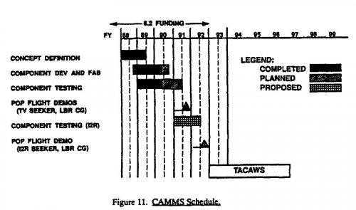
As a summary, the schedule of Figure 11 shows that hardware design and development has been essentially completed. Component testing and algorithm development are on schedule this year and should lead to TV seeker flights in FY91 at the Eglin AFB, FL HELLFIRE test range. If affordable IIR seekers can be obtained, they could be integrated into the test bed missile and flown in FY92 to be ready for TACAWS, an Advanced Technology Transition Demonstration (ATTD) planned to start in FY93.

Proceedings of Technology Showcase Held in Huntsville
Last edited:
