kiradog
ACCESS: Confidential
- Joined
- 3 February 2008
- Messages
- 77
- Reaction score
- 35

kiradog said:Do not think i have posted these in past.
")
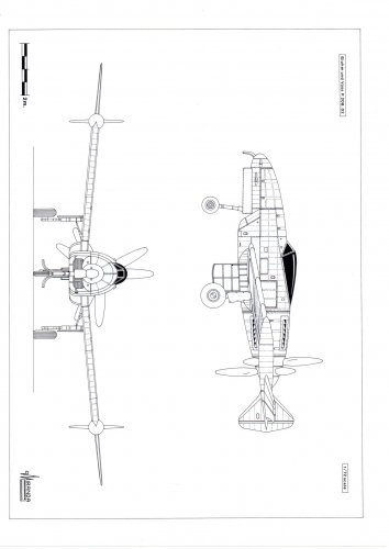
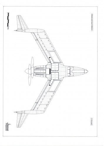
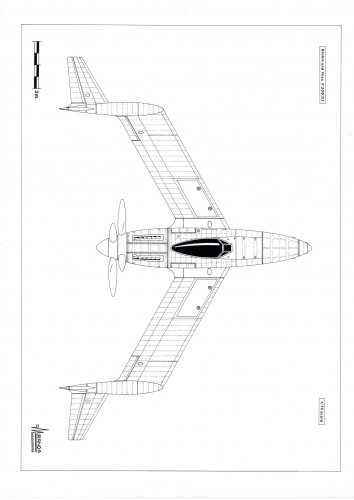
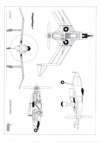
Zizi6785 said:I made an approximate sketch of P.208.01
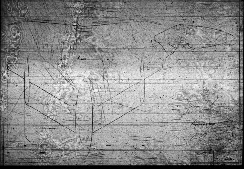
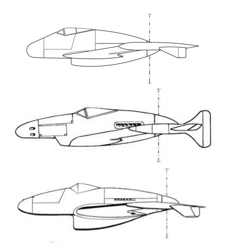
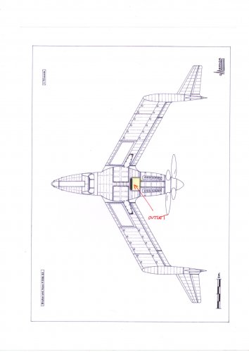
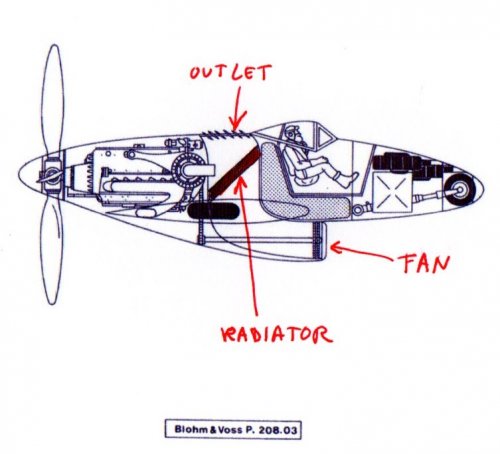
Justo-san, I can't find radiator cooling air outlet nozzle in your P.208.02 drawings. :-[Justo Miranda said:Some especulative stuff for modellers
foiling said:Justo, your artwork is exquisite, as always. Thank you.
Neville Giloi
blackkite said:Justo-san, I can't find radiator cooling air outlet nozzle in your P.208.02 drawings. :-[Justo Miranda said:Some especulative stuff for modellers
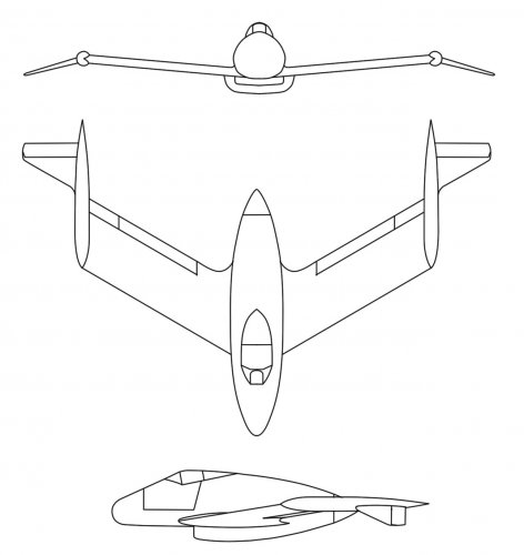
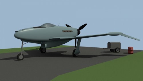
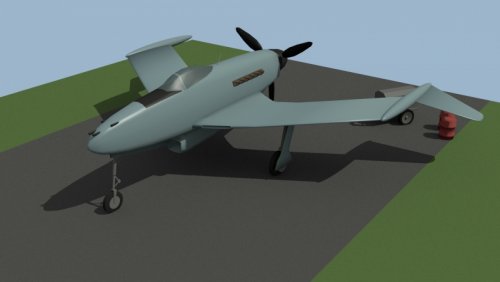
blackkite said:http://www.luft46.com/bv/bvp208.html
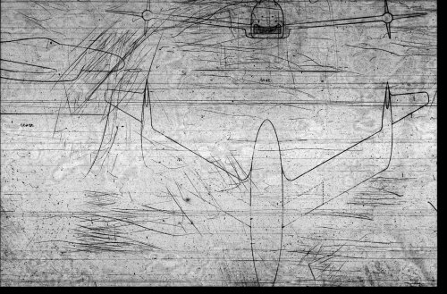
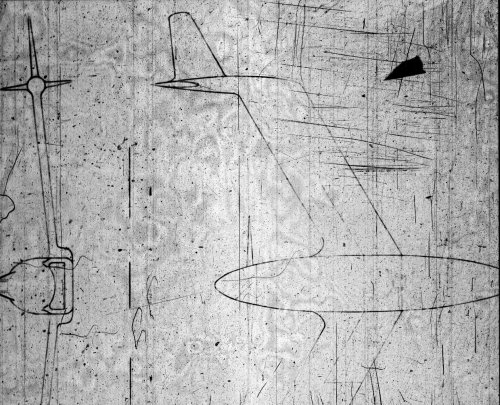
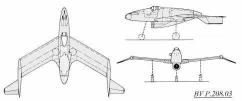
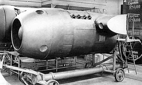
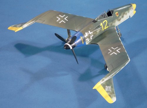
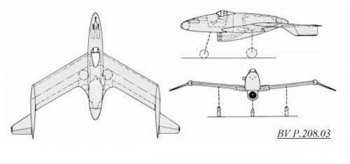
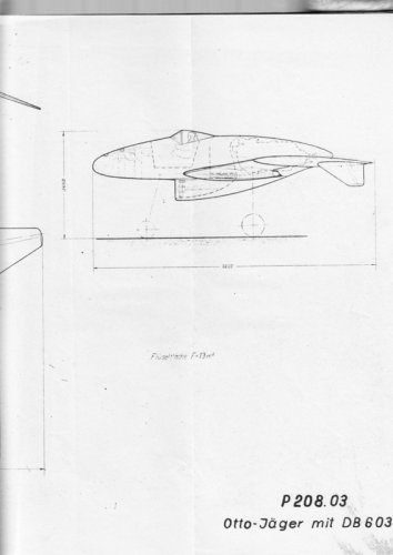
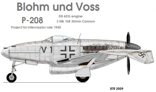
"The BV P.208.03 was the final design for a series of tailless aircraft designs by Blohm und Voß. A single Daimler Benz 12-cylinder DB 603L engine with a two-stage supercharger (2100 HP with MW 50 methanol-water injection) was imbedded within the fuselage aft of the cockpit. The engine drove a pusher propeller and was fed by an air intake located on the starboard side of the fuselage, with the radiator mounted beneath the fuselage."
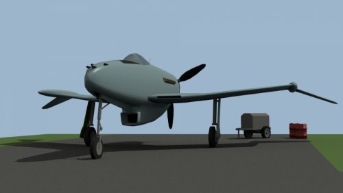
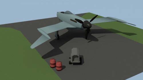
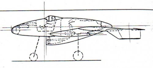
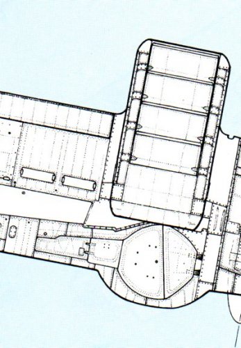
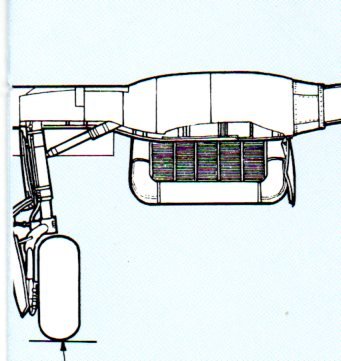
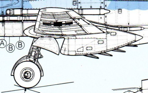
Oh I see. I wonder that main landing gear interfere with air flow and why so long air duct need?Justo Miranda said:blackkite said:Justo-san, I can't find radiator cooling air outlet nozzle in your P.208.02 drawings. :-[Justo Miranda said:Some especulative stuff for modellers
Here
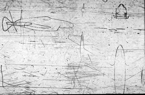
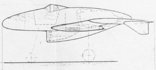
I can't find radiator at this position in the original side view drawing. :-[ I think that radiator is located fuselage bottom, I can see some device here in the original side view drawing.Justo Miranda said:blackkite said:http://www.luft46.com/bv/bvp208.html
"The BV P.208.03 was the final design for a series of tailless aircraft designs by Blohm und Voß. A single Daimler Benz 12-cylinder DB 603L engine with a two-stage supercharger (2100 HP with MW 50 methanol-water injection) was imbedded within the fuselage aft of the cockpit. The engine drove a pusher propeller and was fed by an air intake located on the starboard side of the fuselage, with the radiator mounted beneath the fuselage."
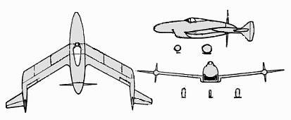
Radiator mounted inside the fuselage
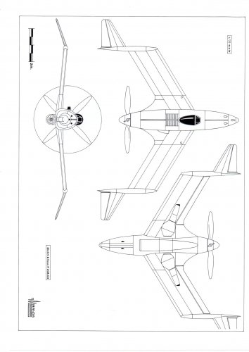
Great work Justo-san.Justo Miranda said:Justo-san drawings
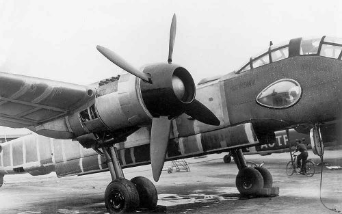
Source Monogram Close-up
Do not think i have posted these in past.
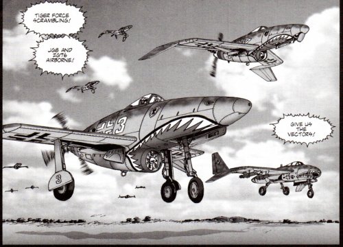
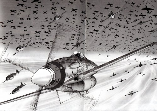
What manga is it looks really neatWagnerian manga by Ted Nomura.
Alternate Wars, Antarctic Press
What comic did you get the images from thanks looks neat.Wagnerian manga by Ted Nomura.
Alternate Wars, Antarctic Press