
You are using an out of date browser. It may not display this or other websites correctly.
You should upgrade or use an alternative browser.
You should upgrade or use an alternative browser.
Amateur RuAF lightweight fighter projects
- Thread starter paralay
- Start date
- Joined
- 29 November 2010
- Messages
- 1,702
- Reaction score
- 3,208
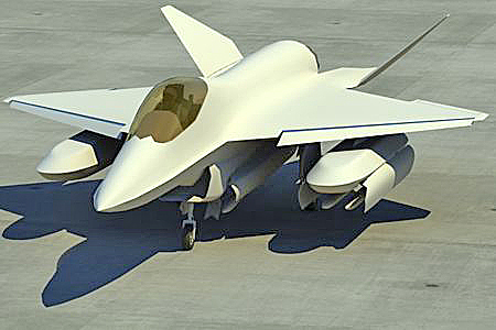
^ well if we are posting fan art..
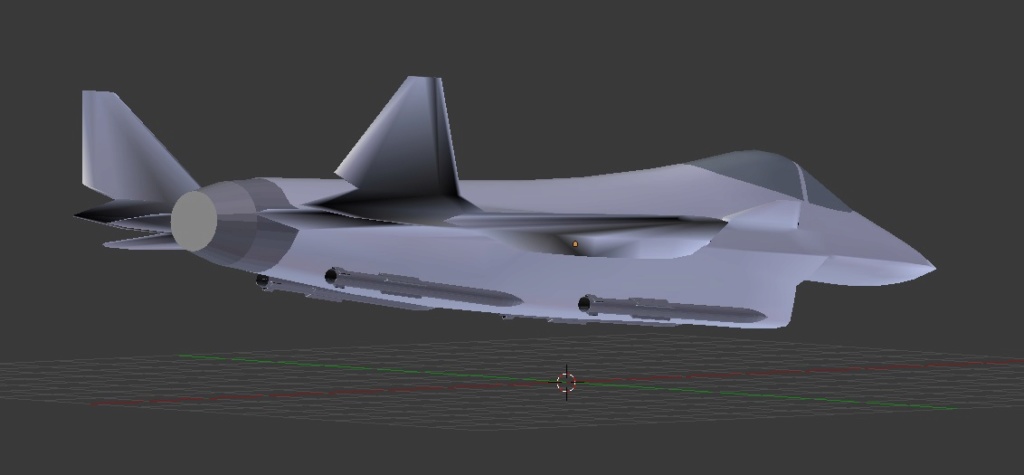
some one made a CG based on that partial model on the desk above

some one made a CG based on that partial model on the desk above
LMFS
ACCESS: Top Secret
- Joined
- 19 March 2019
- Messages
- 511
- Reaction score
- 760
^ well if we are posting fan art..
some one made a CG based on that partial model on the desk above
That is model I did years ago, so it is the Russians that copied me xD
Early version of the plane in my avatar
- Joined
- 29 November 2010
- Messages
- 1,702
- Reaction score
- 3,208
^ well if we are posting fan art..
some one made a CG based on that partial model on the desk above
That is model I did years ago, so it is the Russians that copied me xD
Early version of the plane in my avatar
thats an amazing CG!
LMFS
ACCESS: Top Secret
- Joined
- 19 March 2019
- Messages
- 511
- Reaction score
- 760
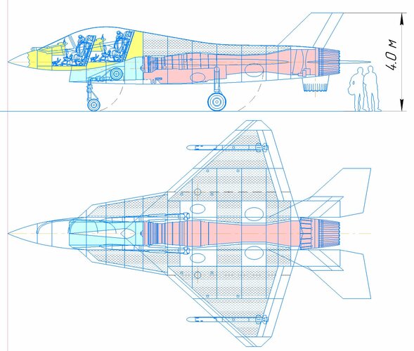
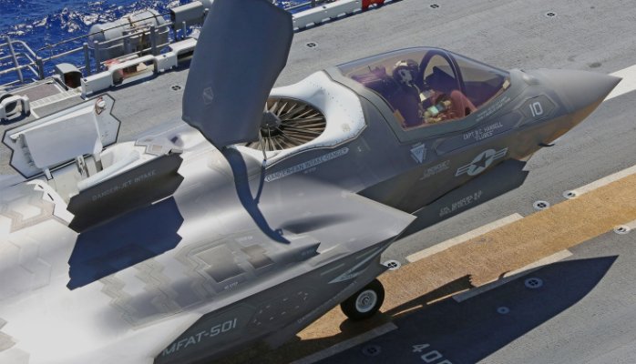
I am sure there will be a single-engine fighter with an engine izd.30. Probably in two variants, horizontal take-off and landing and short take-off and vertical landing for aircraft carrier and universal landing craft
Actually there is a very good option to use such a design as a STOVL platform without falling in many of the traps F-35 fell. Using a lifting fan in an unmanned version of the plane in the place where the cockpit is normally located, there would be freedom to move the main engine backwards and freed the middle section of the plane for fuel and weapons without needing to grow the cross sectional area of the plane. My apologies for the extreme crudity of the sketch below, but the concept is what matters and I don't have time for working on the 3D model now


The very forward placed lifting fan, if a light-enough shaft of that length could realistically move it, would give a lot of freedom for designing the rest of the plane, which in current STOVL designs is not the case. For use onboard an UDK/LHD the UCAV version would be sophisticated enough and already improve a lot the A2A performance of the fleet in absence of real carriers.
- Joined
- 29 November 2010
- Messages
- 1,702
- Reaction score
- 3,208
^ wouldnt the fan right next to the intake create some problems with the air?
LMFS
ACCESS: Top Secret
- Joined
- 19 March 2019
- Messages
- 511
- Reaction score
- 760
^ wouldnt the fan right next to the intake create some problems with the air?
Yeah good observation, that is one of the reasons I apologized for the model. It is crude and incomplete, and the whole setup (doors, main intake redesign, TVC nozzle etc) is not shown, the idea was mainly to understand the weight distribution between nozzle and lifting fan...
But to the question: first of all this is cold, oxygen rich air, so no big problems are to be expected if some air is ingested, as far as I know;
Second, you can use the lower doors that the lifting fan would have to shield the main intake;
Third, you most probably would have a dorsal intake open when the vertical lift is being generated, to ensure undisturbed airflow to the engine
...so I think it could work more or less xD
@LMFS : (I have read you enough to know that you might not have been in your better day writing the above. Hence I know you won't boil-off upon reading the following joke
My much needed input for your design:
Front view:
Last but not least, the blown, suck airflow stream would certainly makes for an interesting call name by the crew...
Some explanations:
My much needed input for your design:
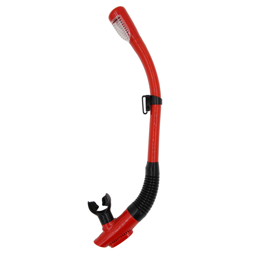
Front view:

Last but not least, the blown, suck airflow stream would certainly makes for an interesting call name by the crew...
Some explanations:
Last edited:
LMFS
ACCESS: Top Secret
- Joined
- 19 March 2019
- Messages
- 511
- Reaction score
- 760
@LMFS : (I have read you enough to know that you might not have been in your better day writing the above. Hence I know you won't boil-off upon reading the following joke
My much needed input for your design:
Hey what we publish here is open for fair criticism. The "snorkel" you suggest is what most STOVL planes have in the form of a dorsal intake, which I already mentioned above.
I don't quite get what you mean with the thrust equation. Even at the risk of being too obvious, do you care explaining? As I see it, the air for the main engine comes from above (dorsal intake remember), but maybe there is no need to close the main intake completely, since the air going downwards from the lifting fan can be shielded from the intake and directed clear of the airframe. Residual ingested air would have little downwards moment and it would be propelled vertically by the TVC nozzle (depicted only in horizontal flight and not deflected position), I don't see any problem with it generating vertical lift...
Cadet Biegler
ACCESS: Restricted
- Joined
- 28 May 2021
- Messages
- 1
- Reaction score
- 0
Hello, did you all wondering about it miss the info that MiG has recently been basically incorporated into Sukhoi, so there will be no more competition between these two, but instead Sukhoi has an access to all MiG's developments, including those concerning new generation single engine fighter projects (which are independent from MiG-29 family, by the way)?Here a bit more realistic...
But now built by Silhouette?? I thought it is a MiG project? ... and any idea how it will be presented at MAKS?
Similar situation as to Kamov-Mil, really; on paper it's a merger, but in reality of course the more dominant partner prevails (not unsimilar to Boeing-McDonnell Douglas merger).Cadet Biegler
Last edited:
The second red equation tells us that thrust when sourced from a static volume of air depends on the speed difference b/w the air at the inlet and exhaust sections.
If two engines (fan and Propulsion) in gets air from the same area (the dorsal inlet you mentions suck air coming roughly from the same area your fan tries to get it), the air at both propulsion devices inlets would be more accelerated than if both devices were widely separated (it's the ventury effect applied to the volume of air above the airframe).
Hence the loss in thrust.
Moreover, the first red equation tells us that the diffencial pressure b/w the inlet and outlet increases the thrust when positive and decrease it it when negative (reverse thrust - theorical case). If you ingest the air from another engine, that difference will be at best minimal what will results in a loss of thrust.
Engine can even stall in such case (remember Topgun sequence when mavericks Tomcat loose an engine while crossing the exhausts trail of his leader).
LMFS
ACCESS: Top Secret
- Joined
- 19 March 2019
- Messages
- 511
- Reaction score
- 760
The second red equation tells us that thrust when sourced from a static volume of air depends on the speed difference b/w the air at the inlet and exhaust sections.
If two engines (fan and Propulsion) in gets air from the same area (the dorsal inlet you mentions suck air coming roughly from the same area your fan tries to get it), the air at both propulsion devices inlets would be more accelerated than if both devices were widely separated (it's the ventury effect applied to the volume of air above the airframe).
Hence the loss in thrust.
Moreover, the first red equation tells us that the diffencial pressure b/w the inlet and outlet increases the thrust when positive and decrease it it when negative (reverse thrust - theorical case). If you ingest the air from another engine, that difference will be at best minimal what will results in a loss of thrust.
Engine can even stall in such case (remember Topgun sequence when mavericks Tomcat loose an engine while crossing the exhausts trail of his leader).
We could go in length with an answer about the many reasons why these considerations above do not apply, but I think this sums it all up:
LMFS
ACCESS: Top Secret
- Joined
- 19 March 2019
- Messages
- 511
- Reaction score
- 760
In the design above the dorsal intake is not represented, but since the lifting fan is much more forward placed and the main engine much more to the rear than in the F-35B, both inlets could be many times further apart. But in any case, you cannot drain the atmosphere through an inlet (Venturi does not apply on open air but to the airflow inside a pipe section) so that the close proximity of both inlets in the F-35B is inconsecuential in that regard.Well you can see that there is quite a separation b/w the fan inlet and the auxiliary one for the main engine.
Since there is an increased velocity from the Air at rest and that at the inlet section, the stream tube is contracted and you can generally says that you have what looks like a venturi. Hence the mention here.
But then @LMFS I don't see how you can't figure that two engines sucking the same air will accelerate that air faster than one of them. It's fairly basic.
Then I pointed you the effect of an accelerated air (speed) and that of a higher air pressure (delta P) in the equation of thrust.
But then @LMFS I don't see how you can't figure that two engines sucking the same air will accelerate that air faster than one of them. It's fairly basic.
Then I pointed you the effect of an accelerated air (speed) and that of a higher air pressure (delta P) in the equation of thrust.
I had drawn an airplane similar to yours but without the canards and the tail surfaces more angled like the yf-23. I'm not an aerospace engineer but I used to build RC airplanes, maybe I'll upload my take on the subject later! I feel that if the Russians are going for the light fighter they are going to make hard decisions. Do they pursue an aircraft capable of operating from a carrier? with the potential of selling it to the Indians? or that ship already sailed for them? If they go for a fighter easy to convert to naval operations I don't see them using only one engine. If they go that route they risk creating a mig-29 2.0 that doesn't seem to offer enough savings to compete with the flanker family. If they go single engine they need to make a mig-21 2.0 so they can be successful selling them. It seems hard to think that they will make something like the f-35.
LMFS
ACCESS: Top Secret
- Joined
- 19 March 2019
- Messages
- 511
- Reaction score
- 760
I don't think so Tomcat. Both intakes have an unrestricted airflow and negligible mutual influence.Since there is an increased velocity from the Air at rest and that at the inlet section, the stream tube is contracted and you can generally says that you have what looks like a venturi. Hence the mention here.
Just to make sure, another drawing (sorry again for the hack) to show roughly the position of the different doors for the vertical lift: top cover for the lifting fan, lower cover of the lifting fan with additional mission of shielding the main intake / channelling the airflow from the fan clear of the airframe and doors for the dorsal intake. You see the situation is much better than in F-35B, which actually works based on the same principle, with dorsal intake and fan much further apart. The necessary thrust relation in hover between main nozzle and fan is ca. 2/3 and 1/3 (because the fan is much further from the CoG) so the fan can be smaller and the shaft lighter/longer than in F-35B. Only drawback is that this layout is not compatible with a manned plane.But then @LMFS I don't see how you can't figure that two engines sucking the same air will accelerate that air faster than one of them.

I think I have seen something like that recently, but please post it. Actually I think it is more likely that the plane does not have canards, mine is a pretty radical layout, and today canards are not so advantageous as some years ago since planes with reduced or negative stability actually get lift and not downforce from conventional tail surfaces. The idea behind this rather exotic layout is to have a triplane MFI-like configuration, which is the best for trimming, maximize the integral aerodynamic layout gains (blended wing body) and have powerful lift augmentation with the canards. A conventional layout is perfectly possible too, and probably less risky. The canted YF-23 tails make sense too, they would save weight though I have not seen Russia experiment with that much.I had drawn an airplane similar to yours but without the canards and the tail surfaces more angled like the yf-23. I'm not an aerospace engineer but I used to build RC airplanes, maybe I'll upload my take on the subject later! I feel that if the Russians are going for the light fighter they are going to make hard decisions. Do they pursue an aircraft capable of operating from a carrier? with the potential of selling it to the Indians? or that ship already sailed for them? If they go for a fighter easy to convert to naval operations I don't see them using only one engine. If they go that route they risk creating a mig-29 2.0 that doesn't seem to offer enough savings to compete with the flanker family. If they go single engine they need to make a mig-21 2.0 so they can be successful selling them. It seems hard to think that they will make something like the f-35.
Agree on the approach you express above for the new fighter. As a naval fighter they will probably have the Su-57. Though this STOVL version discussed above would be of course thought for the UDKs and would be compatible with what we know of the STOVL project ongoing (so Russia has indeed some interest) and that the new plane would have manned and unmanned versions
Last edited:
It's a nice design. I do like it better with the barn doors.
A stream tube is an appelation.
A stream tube is an appelation.


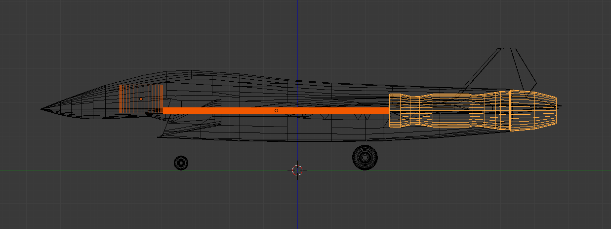
The problem is that, if you are to use a single Izd. 30 for your fighter, the size of the engine cannot be that small in proportion to the airframe, unless you have a very short afterburner section, which here screws up all the prerequisite for your design. In reality it would span from where the blue line is, potentially even further up front.
Firstly, as seen from Harrier, F-35 and other single engine fighter jets, the engine face should be way further forward, which means you cannot position the aux. intake like you did, way behind the intake. Even the F-16 engine face ain't that far behind. This is a problem since it has a ventral intake, which means a dorsal aux. intake and inlet would take a lot of space to be connected to the main inlet duct, potentially just as much as you save up by placing the lifting fan forward.
In this case, you would still need to use the main intake for VTOL operations as well, which means great disruption of airflow by the lift fan that is in front of the main intake, as the jet stream would drag the surrounding air with it causing problems regarding air ingestion for the engine itself.
If the Russians actually make a medium sized single IZD. 30 fighter jet and a STOVL variant of it, it would look much alike the X-32, since there are a lot of similarities. A lift nozzle close to CoG with augmented jet screen that uses bleed air from the bypass, in between the intake and the lift nozzle. If they want to use the lift-fan, there wouldn't be much option other than using the side-intake like the F-35, regardless of the manned cockpit or not.
Just my 2 cents.
Last edited:
LMFS
ACCESS: Top Secret
- Joined
- 19 March 2019
- Messages
- 511
- Reaction score
- 760
The shaft is long and that is one of the technical issues that would need to be checked, of course. But since the amount of power to handle is way smaller than in F-35 (1/3 of total lift instead of 1/2), the solution already works in that plane (shorter shaft I know) and given the many advantages, I think it is at least an option worth considering.I think it would be wiser to bring the lift fan a bit closer to the engine since that shaft that connects the two seems extremely long and as an engineer, I wouldn't want to deal with that kind of thing for an aircraft
The whole idea of the design is precisely to have the lifting fan and the main engine far apart, so that the weapons can be carried in line with the engine in the middle section of the plane and not at the sides like in the F-35. That is a terrible solution for the aero and general layout of the plane.
Yes of course, but the share of the lifting fan is reduced and that is precisely the goal. You cannot extract as much power from the turbine as you want and keep the engine operating effectively as a jet, there are also limits for the shaft and size of the lifting fan. By the way Lockheed crammed the lifting fan into the cockpit and by the very forward position of the main engine you can see they reached the practical limits of the design with a share of lift close to 50:50 and bays parallel to the engine. The price to pay is a terrible supersonic drag.Also I think you're idea is concerning the pitching moment of the engine in relation to the lift fan but I should tell you that the CoG has not much to do with the total mass of the aircraft, which in case of VTOL operation means that you would still need the same amount of combined thrust to lift the aircraft as to if you have the lift fan closer to the CoG.
Yes if you use HW for generating lifting fan you need to remove something else, that is something that needs to be accepted the moment a STOVL plane is developed. In this case you have the space that normally would be used by the pilot gone, but the avionics bay at the nose and after the pilot are almost intact, as well as the fuel tanks and the weapon bays, which are far more important. The radar here is limited by the aperture more than anything else.Also you could potentially use the space where you positioned the lift fan for avionics to support bigger radar.
The internal volume lost in a long air duct is a better compromise than increased drag because there is no place for the weapon bays in line with the engine. Side intakes with S duct and confluence in front of the engine mean the central section of the plane cannot be used for the weapon bays or if you do it, you get swallow bays like in F-22. So you would get more drag and weight having to move the bays to the sides of the engine or losing the ability to carry big A2G weapons. The original design of this plane is CTOL and the whole idea of the sketch above is to get a STOVL layout without affecting the performance of the more numerous and more critical CTOL one, contrary to what happened with the F-35. Ventral intake for a single engine is simpler, lighter and less draggy, and IMHO it allows to accommodate the weapon bays, since the air duct does not need to be perfectly straight, unlike the engine or the weapons.That's a lot of space wasted, ie it's better off means no ventral VTOL intake.
This is how it works in the F-35 so I see no airflow problem. Eventually the doors of the dorsal intake could be substituted with a single door inclined forward, helping capture more air when the plane starts moving forward, like that at the lifting fan of the F-35.I see that for that reason you have place the secondary intake closer to the engine far behind the primary intake, but that would cause another air flow problem.
See the discussion above, the main intake would be shielded from the flow of the lifting fan, since there is an alternative air intake the main one can be closed, and the very shape of the lower door roughly at the DSI bump can be used for that. Some planes take off with closed main intakes, like the Yak-130 and old MiG-29. The main problem I would see otherwise is not the lack of airflow to the main engine but rather the fan airflow being sucked into the intake, reducing lift because the air would interact with the airframe instead of transferring moment to the surroundings and eventually to the ground. Therefore the convenience to steer it past the intake.This also means that you would need to use you conventional intake for both the VTOL and horizontal flight operations, which means that the lift fan position is very problematic in terms of air flow, since it will drag the air near the jet stream with it, meaning substantial drop-off of airflow to the engine itself.
Due to the separation between the intake and the nozzle, the fact that the air from the fan is already screening the exhaust air from reaching the main intake, the existence of the roll posts and the presence of the dorsal intake, I don't see that as a big problem. It is much more critical that the forward lifting device in this case is a fan and not an engine, because that air is much more prone to be ingested by the intakes, which are also forward placed.Also, in such case where you need to use the same intake for VTOL and normal flight profiles, there's another reason you would like to have your lift fan closer to you engine, which is the screening effect of the exhaust gas from the engine nozzle. Harrier's forward nozzle was bypass-air-only and the X-32 had a separate screening device which bled the air from the engine. F-35's lift fan serves the same function as well, although its importance is lower since there's a separate intake on the ventral surface. These kind of screening device, either augmental like the X-32 or thrust related like the harrier, should be placed in between the intake and the engine itself, which is not the case in your
Thanks for the reasoned criticism!My 5 cents.
Sorry LMFS, while you were writing your reply I had to edit my own post because I've found out that my own prerequisite, embarrassingly, was wrong! I wonder what's your take about my new comment on the design(about the aircraft proportion)? I see that some of your points apply regardless, like you take about the dorsal aux. intake. Regardless, thank you for the explanation.The shaft is long and that is one of the technical issues that would need to be checked, of course. But since the amount of power to handle is way smaller than in F-35 (1/3 of total lift instead of 1/2), the solution already works in that plane (shorter shaft I know) and given the many advantages, I think it is at least an option worth considering.I think it would be wiser to bring the lift fan a bit closer to the engine since that shaft that connects the two seems extremely long and as an engineer, I wouldn't want to deal with that kind of thing for an aircraft
The whole idea of the design is precisely to have the lifting fan and the main engine far apart, so that the weapons can be carried in line with the engine in the middle section of the plane and not at the sides like in the F-35. That is a terrible solution for the aero and general layout of the plane. [...]
Thanks for the reasoned criticism!My 5 cents.
I think it's an interesting topic to discuss regarding the dorsal aux. intake, if it's worth the long inlet duct.
Wait, maybe even my edited comment is false as well. If we consider the Izd. 30 to be somewhere in the region of the 5m length, that model hasn't got much problem. I guess I messed up? My apologies LMFS. I guess there were some visual deception due to the size and position of the wings I guess.
Regardless, I still have some questions, like this one :
Maybe there could be some compensation for the fuel tank compartment since there is no cockpit? I guess that way it might be able to have as much fuel + s duct over the weapons bay that could house 2 2,000 lbs JDAM.
Regardless, I still have some questions, like this one :
I should question that a bit, since the problem with the F-35 being that thick was to have a 2,000 lbs JDAM internally + large amount of fuel, which are all mounted on the upper half of the fuselage. As long as you have your inlet duct spanning through, your IWB will need to be placed on the side of the inlet duct regardless of the lift fan position, unless you are okay with either less fuel or/and less internal weapons payload wouldn't it? I guess you are thinking about an inlet duct that goes over the IWB but that would be where large part of the fuel tanks are for the F-35. Well at least that solves the problem of dorsal aux. duct taking up too much space, as it would be reasonably close to the inlet duct.The whole idea of the design is precisely to have the lifting fan and the main engine far apart, so that the weapons can be carried in line with the engine in the middle section of the plane and not at the sides like in the F-35. That is a terrible solution for the aero and general layout of the plane.
Maybe there could be some compensation for the fuel tank compartment since there is no cockpit? I guess that way it might be able to have as much fuel + s duct over the weapons bay that could house 2 2,000 lbs JDAM.
Last edited:
So to sum up does the internal compartment of your LMFS/LFI UCAV look like this? :

F-35 in comparison :

so the F3 tank counterpart would be substantially smaller/deleted, while the F2 counterpart would be way bigger in your design, if I understood correctly.

F-35 in comparison :

so the F3 tank counterpart would be substantially smaller/deleted, while the F2 counterpart would be way bigger in your design, if I understood correctly.
LMFS
ACCESS: Top Secret
- Joined
- 19 March 2019
- Messages
- 511
- Reaction score
- 760
No problem, publishing the idea means opening it to criticism. Thanks for being constructiveWait, maybe even my edited comment is false as well. If we consider the Izd. 30 to be somewhere in the region of the 5m length, that model hasn't got much problem. I guess I messed up? My apologies LMFS. I guess there were some visual deception due to the size and position of the wings I guess.
The problem of the F-35 IMHO is not the size of the JDAMs per se, is the fact that they placed those big bays in parallel with the engine. What I consider a good fighter design takes the unavoidable sources of cross sectional area (engine and cockpit mainly) and wraps all the rest of the elements as tight as possible within that footprint. That means, in a single engine plane, to place the IWB in line with the engine and not in parallel. For instance, F-16 is a little more than 4 sqm across, while F-35 is more than 8 sqm.I should question that a bit, since the problem with the F-35 being that thick was to have a 2,000 lbs JDAM internally + large amount of fuel, which are all mounted on the upper half of the fuselage. As long as you have your inlet duct spanning through, your IWB will need to be placed on the side of the inlet duct regardless of the lift fan position, unless you are okay with either less fuel or/and less internal weapons payload wouldn't it? I guess you are thinking about an inlet duct that goes over the IWB but that would be where large part of the fuel tanks are for the F-35. Well at least that solves the problem of dorsal aux. duct taking up too much space, as it would be reasonably close to the inlet duct.
You are right, my layout bends the air duct over the main IWB, which is roughly the same size as the bay of the PAK-FA, maybe a bit swallower and not as regular, but the challenge in such a small plane is difficult. There are, besides, two quick bays on the wing root also like the PAK-FA and two rail launchers for MRAAM at the sides of the air channel. Big A2G ordnance is best dropped, but missiles with capability for rail launch are more flexible in that regard. Does it fit all together? No idea, actual designers would need to say. But the result is small enough to think that a certain increase of size would not kill the concept. Izd. 30 appears to be a 18 tf engine with higher mil thrust than the F119, so it should move a plane like this with ease.
Well if the lifting fan uses up the space of the cockpit there is no fuel advantage over the manned version and probably a certain loss compared to the unmanned CTOL one. STOVL normally destroys the layout of a plane, as well as its weight, payload and fuel capacity, so this is not so bad I think. Some additional doors, roll posts, some loss in the dorsal tanks because of the intake there, but very limited IMHO. I post some drawings to better understand the layout. The dorsal intake would be very close to the engine compressor, where the tank is most swallow.Maybe there could be some compensation for the fuel tank compartment since there is no cockpit? I guess that way it might be able to have as much fuel + s duct over the weapons bay that could house 2 2,000 lbs JDAM.
The main IWB has the width and length of those in the PAK-FA and is therefore sized for 2x Kh-69 type of ordnance. Very tight, but it fits. All internal weapons suppose folding fins, if you go for this type of plane doing otherwise makes no sense IMHO. Conformal carriage at lower corner of the intake may also be possible.
Plane is 15.4x9.65x3.6 m, empty weight is ca. 10 t. Gross fuel capacity is 6.9 t, I assume real capacity (removing structure, fuel lines, etc etc) can reach close to 6 t, which is a very good value. Saab did some similar exercise and their values were not so different, so I guess I am not off by too much.


Last edited:
Similar threads
-

-
 Shenyang Jianjiji-11 / J-11 Lightweight Fighter
- Started by Deino
- Replies: 11
-

-
 Westland VTOL convertiplane projects
- Started by overscan (PaulMM)
- Replies: 44
-
