
You are using an out of date browser. It may not display this or other websites correctly.
You should upgrade or use an alternative browser.
You should upgrade or use an alternative browser.
Advanced Medium STOL Transport (AMST) and its predecessors
- Thread starter Pioneer
- Start date
- Joined
- 29 January 2008
- Messages
- 840
- Reaction score
- 1,356
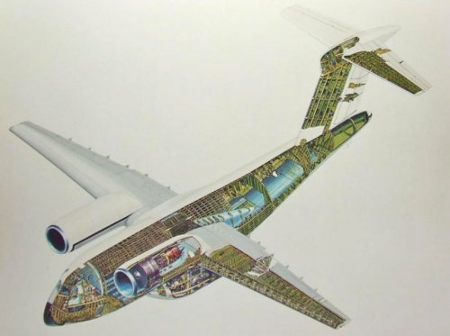
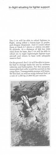
Black/white images from Boeing document. I did not know about the refueling capability. The color cutaway was posted earlier in the thread but I tried photoshop on it to clean it up some.
Attachments
- Joined
- 27 December 2005
- Messages
- 16,442
- Reaction score
- 19,104
Attachments
Last edited:
- Joined
- 27 December 2005
- Messages
- 16,442
- Reaction score
- 19,104
In mid-1970, the Air Force contracted with Boeing, McDonnell Douglas, Fairchild, and another company or two to study various types of tactical aircraft transports. This study was called the Tactical Aircraft Investigation (TAl).
The report and drawing above appears to be from pre-AMST studies, MST (Required Operational Capability (ROC) 52-69, Medium STOL Transport) and then TAI.
According to John K. Wimpress & Conrad F. Newberry in the AIAA book on the YC-14, AMST proposals were made by Boeing, McDonnell Douglas, Lockheed-Georgia, Fairchild Industries, and Bell. Convair/General Dynamics did not bid.
- Joined
- 27 December 2005
- Messages
- 16,442
- Reaction score
- 19,104
Attachments
- Joined
- 27 December 2005
- Messages
- 16,442
- Reaction score
- 19,104
Boeing STOL Tactical Aircraft Investigation (TAI) Reports (1971-1973)
Vol 1 - Configuration Definition : Medium STOL Transport with Vectored Thrust/Mechanical Flaps
https://apps.dtic.mil/dtic/tr/fulltext/u2/766637.pdf
Vol 2 Part 1 - Aerodynamic Technology: Design Compendium, Vectored Thrust/Mechanical Flaps
https://apps.dtic.mil/dtic/tr/fulltext/u2/766639.pdf
Vol 3 - Takeoff and Landing Performance Ground Rules for Powered Lift STOL Transport Aircraft
https://apps.dtic.mil/dtic/tr/fulltext/u2/766640.pdf
Vol 4 - Analysis of Wind Tunnel Data: Vectored Thrust/Mechanical Flaps and Internally Blown Jet Flaps
https://apps.dtic.mil/dtic/tr/fulltext/u2/766641.pdf
Vol 5 Part 1 - Flight Control Technology: System Analysis and Trade Studies for a Medium STOL Transport with Vectored Thrust/Mechanical Flaps
https://apps.dtic.mil/dtic/tr/fulltext/u2/766642.pdf
Vol 5 Part 2 - Flight Control Technology: Piloted Simulation of a Medium STOL Transport with Vectored Thrust Mechanical Flaps
https://apps.dtic.mil/dtic/tr/fulltext/u2/766643.pdf
Vol 6 - AIR CUSHION LANDING SYSTEM STUDY
https://apps.dtic.mil/dtic/tr/fulltext/u2/766644.pdf
Last edited:
- Joined
- 27 December 2005
- Messages
- 16,442
- Reaction score
- 19,104
Rockwell STOL Tactical Aircraft Investigation - Externally Blown Flap. (1971-1972)
Vol 2 Design Compendium
https://apps.dtic.mil/dtic/tr/fulltext/u2/770110.pdf
Vol 3 PERFORMANCE METHODS AND LANDING RULES
https://apps.dtic.mil/dtic/tr/fulltext/u2/767180.pdf
Vol 5 Part 1. CONTROL SYSTEM MECHANIZATION TRADE STUDIES
https://apps.dtic.mil/dtic/tr/fulltext/u2/767181.pdf
Vol 5 Part 2 - Flight Control Technology. Simulation Studies/Flight Control System Validation.
https://apps.dtic.mil/docs/citations/AD0770449 (no download)
General Dynamics (Convair) STOL Tactical Aircraft Investigation (1971-1973)
Vol 1 Configuration Definition
https://apps.dtic.mil/dtic/tr/fulltext/u2/766941.pdf
Vol 2 Design Compendium
https://apps.dtic.mil/dtic/tr/fulltext/u2/767561.pdf
Vol 3 Performance Ground Rules and Methods. Book 1 - Takeoff and Landing Ground Rules
https://apps.dtic.mil/dtic/tr/fulltext/u2/766942.pdf
Vol 3 Performance Ground Rules and Methods. Book 2 Takeoff and Landing Digital Computer Program.
https://apps.dtic.mil/dtic/tr/fulltext/u2/766943.pdf
Vol 4 Wind Tunnel Data Analysis
https://apps.dtic.mil/dtic/tr/fulltext/u2/767363.pdf
Vol 5 Flight Control Technology
https://apps.dtic.mil/dtic/tr/fulltext/u2/767364.pdf
Vol 6 Air Cushion and Ground Mobility Study
https://apps.dtic.mil/dtic/tr/fulltext/u2/767300.pdf
Vol 2 Design Compendium
https://apps.dtic.mil/dtic/tr/fulltext/u2/770110.pdf
Vol 3 PERFORMANCE METHODS AND LANDING RULES
https://apps.dtic.mil/dtic/tr/fulltext/u2/767180.pdf
Vol 5 Part 1. CONTROL SYSTEM MECHANIZATION TRADE STUDIES
https://apps.dtic.mil/dtic/tr/fulltext/u2/767181.pdf
Vol 5 Part 2 - Flight Control Technology. Simulation Studies/Flight Control System Validation.
https://apps.dtic.mil/docs/citations/AD0770449 (no download)
General Dynamics (Convair) STOL Tactical Aircraft Investigation (1971-1973)
Vol 1 Configuration Definition
https://apps.dtic.mil/dtic/tr/fulltext/u2/766941.pdf
Vol 2 Design Compendium
https://apps.dtic.mil/dtic/tr/fulltext/u2/767561.pdf
Vol 3 Performance Ground Rules and Methods. Book 1 - Takeoff and Landing Ground Rules
https://apps.dtic.mil/dtic/tr/fulltext/u2/766942.pdf
Vol 3 Performance Ground Rules and Methods. Book 2 Takeoff and Landing Digital Computer Program.
https://apps.dtic.mil/dtic/tr/fulltext/u2/766943.pdf
Vol 4 Wind Tunnel Data Analysis
https://apps.dtic.mil/dtic/tr/fulltext/u2/767363.pdf
Vol 5 Flight Control Technology
https://apps.dtic.mil/dtic/tr/fulltext/u2/767364.pdf
Vol 6 Air Cushion and Ground Mobility Study
https://apps.dtic.mil/dtic/tr/fulltext/u2/767300.pdf
- Joined
- 5 May 2007
- Messages
- 346
- Reaction score
- 333
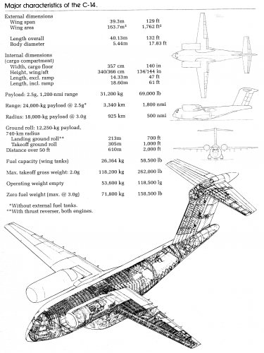
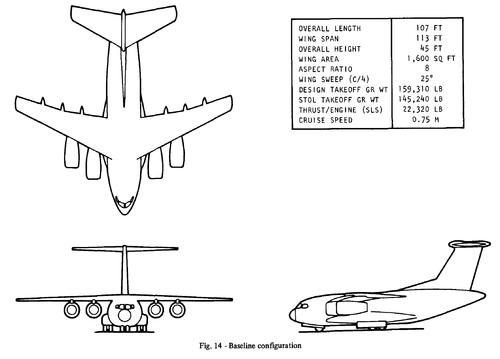
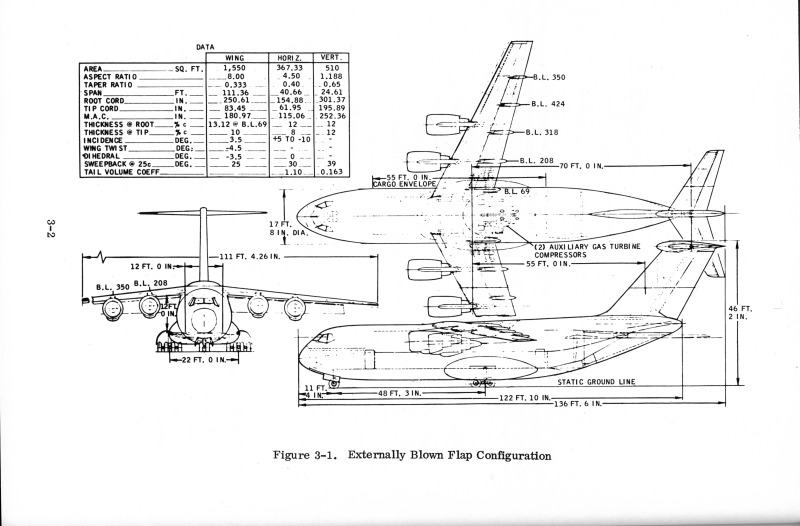
Thanks. Here's a three-view, with specifications, posted on Flickr by the San Diego Air & Space Museum (SDASM) Archives this past April. I figured it was AMST-related. Great to see this additional info.
https://www.flickr.com/photos/sdasmarchives/47477227802
- Joined
- 5 May 2007
- Messages
- 346
- Reaction score
- 333
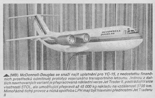
Posted to YouTube today (6-May-2020) by Periscope Film, a circa-1977 McDonnell Douglas promotional film for the YC-15.
Included is footage of the larger wing (132-ft wingspan vs. the original of 110-ft span) later fitted to prototype No. 1 (USAF Ser. No. 72-1875) (beginning at the 5min 7sec mark), as well as the the placement of a CFM56 at the No. 1 position (5min 34sec mark) on the new wing (it is shown in flight at the 7min 18 sec mark). There is also some nice footage throughout of demonstration flights of prototype No. 2 (USAF Ser. No. 72-1876) at Farnborough, in 1976. In addition, the installation of a JT8D-209 engine at 72-1876's No. 1 position (7min 18sec mark) is shown, along with flight footage at the 7min 40sec mark.
YouTube - Periscope Film: 1976 MCDONNELL DOUGLAS CORP. YC-15 TACTICAL TRANSPORT AIRCRAFT PROMO FILM 67544
- Joined
- 27 September 2006
- Messages
- 5,744
- Reaction score
- 5,620
If you are interested in this and other US airlifter projects you need this book
- Joined
- 27 December 2005
- Messages
- 16,442
- Reaction score
- 19,104
In an effort to sell the AMST, Boeing and McDonnell Douglas proposed the use of the YC-14 and the YC-15 for various missions including mid-air launching of ICBMs. A McDonnell Douglas YC-15, fitted with CFM56 engines, is shown in this artist's concept air launching an MX missile.
Source: Norton, Bill STOL Progenitors: The Technology Path to a Large STOL Aircraft and the C-17 American Institute of Aeronautics and Astronautics, Inc. 2002
Mike Machat did this painting, and has posted it in colour on his Facebook Group Aviation History through the art of Mike Machat!
Attachments

Hank58
ACCESS: Restricted
- Joined
- 9 June 2020
- Messages
- 40
- Reaction score
- 160
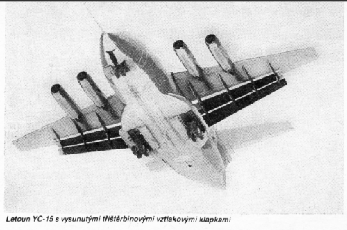
That's a model of the Lockheed AMST proposal version LG-203X. Lockheed's 1972 proposal for the AMST competition was an offering of three differently optimized, but very similar designs: the LG-201X, LG-202X, and the LG-203X. All had blown leading & trailing edge flaps and four vectored-thrust turbofans with Pegasus-style nozzles. The LG-201X design was said to meet all the AMST performance and cargo box requirements, but Lockheed acknowledged its cost would exceed proposed funding. The less expensive LG-202X compromised some performance and had a shorter cargo box, but still exceeded cost. The LG-203X met the AMST RFP performance goals, but had a smaller cargo box cross section to meet the AMST cost requirements. Perhaps these honest cost-performance tradeoffs and complicated three-design proposal cost Lockheed the AMST competition.Paul posted a picture of a model of the Lockheed AMST in this thread
http://www.secretprojects.co.uk/forum/index.php/topic,3825.msg35499.html#msg35499
You can see the engines' exhaust looks flattened. Does anyone know what the powered lift mechanism employed was? Externally blown flaps? vectored exhaust ???
Hank58
ACCESS: Restricted
- Joined
- 9 June 2020
- Messages
- 40
- Reaction score
- 160
Working on a handful of illustrations of the Lockheed AMST proposal family. I have access to a few 30-to-40-year-old photocopies of the almost 50-year-old design. The more I pull together, the more impressed I am with the design. Here is a grainy isometric view of the LG-202X variant, the Pegasus-style nozzles are barely visible, but the oversized fin with its double-hinged and double-slotted rudder is a testament to the very low-speed aspirations of this STOL transport:
Attachments
Hank58
ACCESS: Restricted
- Joined
- 9 June 2020
- Messages
- 40
- Reaction score
- 160
Still slowly working on a handful of illustrations of the Lockheed AMST proposal family. Today's shows the three family members roughly to scale: the LG-201X, LG-202X, and the smaller LG-203X (compromised to meet the stringent cost goals in the AMST RFP by employing the C-130 forward fuselage and cargo box, but missing the 12-ft by 12-ft cargo box cross section AMST requirement).
Attachments
Hank58
ACCESS: Restricted
- Joined
- 9 June 2020
- Messages
- 40
- Reaction score
- 160
Still slowly working on a few more illustrations of the Lockheed AMST proposal. Today's shows the heart of the STOL features of the LG-202X. The Lockheed and North American Rockwell Corporation AMST was designed around blown leading and trailing edge flaps (demonstrated earlier on the C-130BLC) with four TF33-P-7 turbofan engines featuring vectored-thrust using Pegasus-style vectoring nozzles. The attached illustration shows how these unique features were packaged (in the future I'll try to distill what performance numbers I can pull together to show how this would work on a tactical STOL airlifter). Enjoy!
Attachments
- Joined
- 27 December 2005
- Messages
- 16,442
- Reaction score
- 19,104
very nice work.
Hank58
ACCESS: Restricted
- Joined
- 9 June 2020
- Messages
- 40
- Reaction score
- 160
Some performance numbers I promised a while back to work up on the joint Lockheed & North American AMST proposal.
The AMST original 1972 RFP requirements were 27,000 lbs cargo into a 2000-ft-long semi-prepared field (over a 50-ft obstacle) at a radius of 500 NM (no refueling at that austere field). So, almost a 1000 NM range (except the return leg could be empty).
That 500 NM radius was later relaxed to 400 NM for the YC-14 and YC-15. For reference, a C-130E in the early 1970s required about 4000 ft of runway when carrying 27,000 lb of cargo.
The Lockheed & North American Rockwell AMST proposal, the LG-202X, with blown leading and trailing edge flaps and the four vectored-thrust turbofans made the RFP field requirements by having an approach speed of 80-90 KTAS (rate of sink just under 1000 ft per minute, 16 fps) at a mid-mission weight of just under 150,000 lb for the demonstrator. Approach speeds down to 70 KTAS in extreme conditions were quoted (at 1.15 Vstall). That was possible by the blown flaps and thrust vectoring producing trimmed CL of 4 to about 6 at 10 deg AOA (depending on the lift contribution from the vectored thrust, varying by vector angle and engine power setting).
The C-130E at about that weight (close to the 155,000 lb MTOW for the C-130E) has an approach speed at 100% flap of about 145 KIAS.
A final note, the urban legend for the Boeing YC-14 AMST demonstrator is a measured flight speed of 59 KIAS (no altitude quoted, but it must have been high enough to recover from an emergency engine out, because the powered-lift configuration of the twin-engine YC-14 was characterized in the STOL landing approach as an EODT*).
*EODT: Engine-Out Death Trap
- Joined
- 3 June 2006
- Messages
- 2,841
- Reaction score
- 2,530
Hi folks,
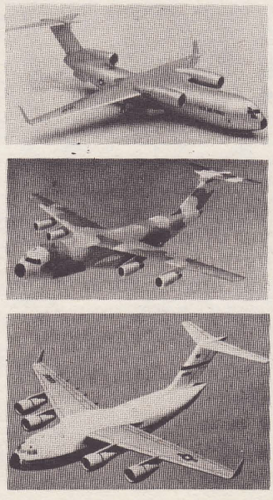
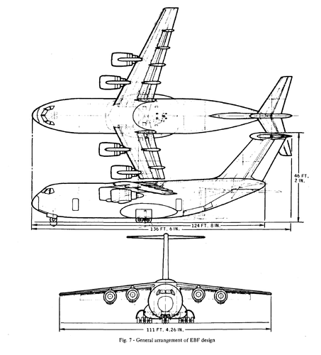
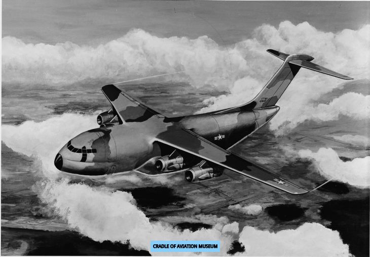
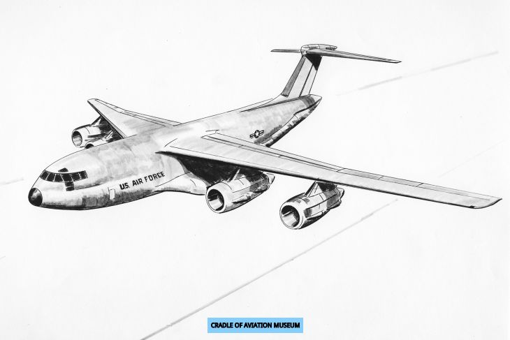
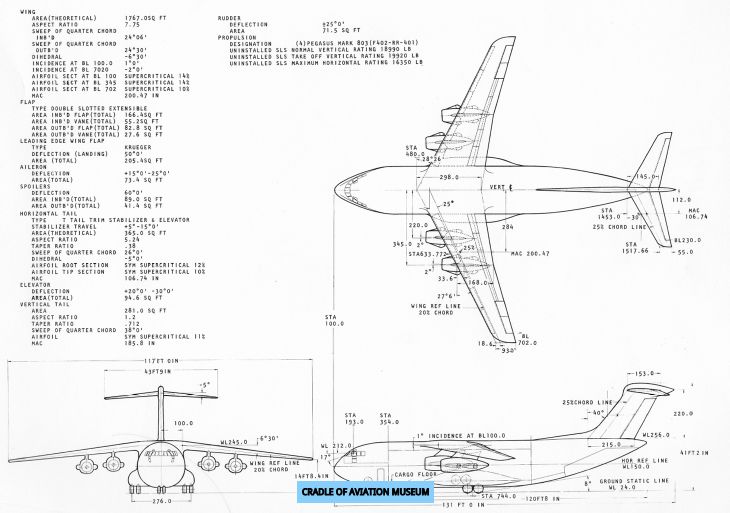
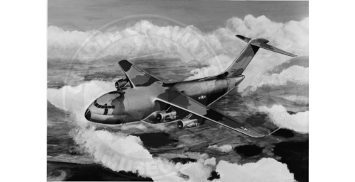
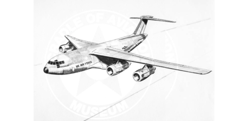
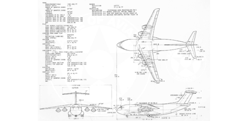
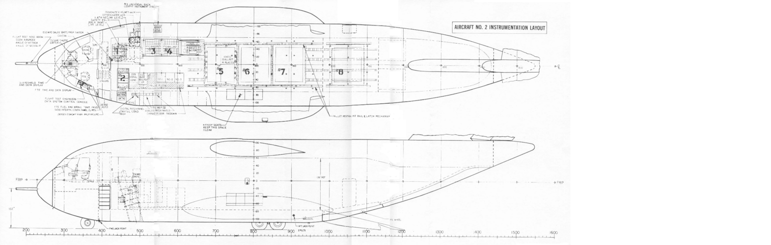
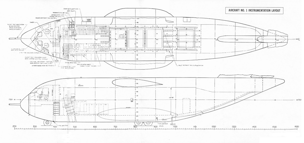
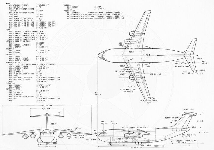
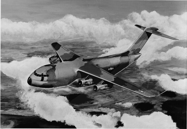
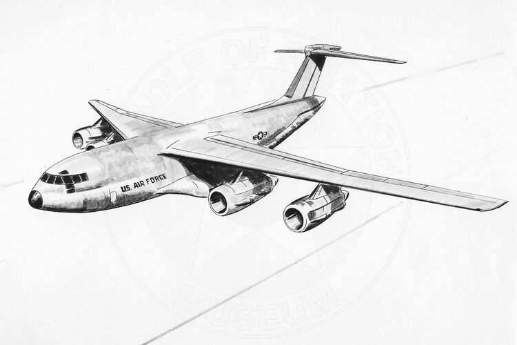
I found these three mislabeled pictures at the Cradle of Aviation Museum two to three months ago, but I had to get the book "American Secret Projects 3: US Airlifters since 1962" in my hands first, before I could confirm, that these three pictures show the Fairchild Republic AMST proposal. Only the three-view general arrangement is shown in Chapter 5, page 121, of that book.")
Links / Sources:
 cdm16694.contentdm.oclc.org
I found these three mislabeled pictures at the Cradle of Aviation Museum two to three months ago, but I had to get the book "American Secret Projects 3: US Airlifters since 1962" in my hands first, before I could confirm, that these three pictures show the Fairchild Republic AMST proposal. Only the three-view general arrangement is shown in Chapter 5, page 121, of that book.
Links / Sources:
C-5B three-view drawing
Fairchild Republic Subcontracts - C-5B, F-4, 747, SST
Attachments
- Joined
- 1 May 2007
- Messages
- 2,459
- Reaction score
- 1,453
Hi folks,
I found these three mislabeled pictures at the Cradle of Aviation Museum two to three months ago, but I had to get the book "American Secret Projects 3: US Airlifters since 1962" in my hands first, before I could confirm, that these three pictures show the Fairchild Republic AMST proposal. Only the three-view general arrangement is shown in Chapter 5, page 121, of that book.
Links / Sources:
C-5B three-view drawing
Fairchild Republic Subcontracts - C-5B, F-4, 747, SST
Shades of HS.681 . . .
cheers,
Robin.
Hank58
ACCESS: Restricted
- Joined
- 9 June 2020
- Messages
- 40
- Reaction score
- 160
Excellent find. I love the full Pegasus engine installations (all four "posts"), unlike the Lockheed installation using the pair of Pegasus-style nozzles (two "posts" per engine). The rest of the jet is borderline "fugly". The cockpit transparencies (windshield/windscreen) geometry just looks wrong. The paradrop windows suggest there is little instrument panel (likely not true). The fuselage afterbody looks like a hopeless structural and drag mess with the upsweep angle and no "banana" for a torque-box! Finally, what is up with that double-bubble crease on the nose under the cockpit?Hi folks,
I found these three mislabeled pictures at the Cradle of Aviation Museum two to three months ago, but I had to get the book "American Secret Projects 3: US Airlifters since 1962" in my hands first, before I could confirm, that these three pictures show the Fairchild Republic AMST proposal. Only the three-view general arrangement is shown in Chapter 5, page 121, of that book.
Links / Sources:
C-5B three-view drawing
Fairchild Republic Subcontracts - C-5B, F-4, 747, SST
- Joined
- 4 May 2008
- Messages
- 2,440
- Reaction score
- 675
The nose does indeed look weird. I thought the horizontal line might denote nose doors, but the retracted nose landing gear unit would block much of the volume if that were the case. I dunno, i'm not sure either way.
The lack of 'banana tail' might be due to the depth of the fuselage - it's pretty thick. You might be able to fit a decent structural layout in the available space without resorting to the banana. But this is speculation on my part, maybe they did screw up!
The lack of 'banana tail' might be due to the depth of the fuselage - it's pretty thick. You might be able to fit a decent structural layout in the available space without resorting to the banana. But this is speculation on my part, maybe they did screw up!
Hank58
ACCESS: Restricted
- Joined
- 9 June 2020
- Messages
- 40
- Reaction score
- 160
Yes, that crease is meant to show that the crew compartment (specifically the flight deck) is within the upper bubble and the volume below is in a second bubble. Think of pinching in the sides of a round letter "O" (the floor of the flight deck is the tension member holding that pinch in). The C-5 has a small diameter upper bubble for the crew, and a larger diameter lower bubble for the cargo box. Forward of the wing, the drag reduction of a fairing to smooth over the crease paid for its extra weight. Aft of the wing, not so much (so no fairing and a distinctive crease). See the two photos:The nose does indeed look weird. I thought the horizontal line might denote nose doors, but the retracted nose landing gear unit would block much of the volume if that were the case. I dunno, i'm not sure either way.
The lack of 'banana tail' might be due to the depth of the fuselage - it's pretty thick. You might be able to fit a decent structural layout in the available space without resorting to the banana. But this is speculation on my part, maybe they did screw up!


- Joined
- 9 October 2009
- Messages
- 19,884
- Reaction score
- 10,393
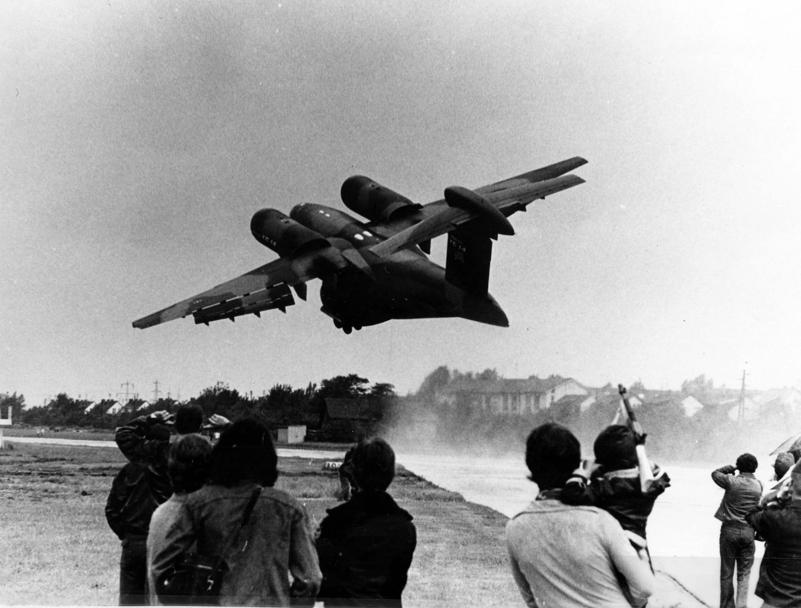
Boeing YC-14: You’ve Been “Coanded”.
To me nothing could compare to the cool YC-14. I know, the Antonov An-72/74 shares (copied) the same configuration, but Boeing’s was the big real deal.Awe-inspiring photo too.
 elpoderdelasgalaxias.wordpress.com
Green with envy…Glad to hear you liked the pic. The article from Flug Revue about Le Bourget 77 is fascinating. You were really fortunate to be there.
There was a 1:1 fully transparent Mirage F-1 mockup on exhibition and a Mirage 2000 mockup.
- Joined
- 27 December 2005
- Messages
- 16,442
- Reaction score
- 19,104
- Joined
- 16 April 2008
- Messages
- 8,378
- Reaction score
- 10,271
Fairchild Republic proposal for Advanced Medium STOL Transport.
- Joined
- 27 December 2005
- Messages
- 16,442
- Reaction score
- 19,104
Keyboard Commando
Haunebu Pilot
- Joined
- 16 August 2015
- Messages
- 59
- Reaction score
- 66
Not sure if this has been answered already, I've read the specs and know they both met Air Force requirements, but is there any evidence they preferred one over the other (YC-14 and YC-15)?
- Joined
- 3 September 2006
- Messages
- 1,387
- Reaction score
- 1,211
Thanks for those.Larger copies of the Fairchild AMST proposals.
Was it a version of the Lokhheed C-5 Galaxy? under contract from Lockheed?
- Joined
- 27 December 2005
- Messages
- 16,442
- Reaction score
- 19,104
Im pretty sure the description is an error from the archivist. It has nothing to do with the C-5.Thanks for those.Larger copies of the Fairchild AMST proposals.
Was it a version of the Lokhheed C-5 Galaxy? under contract from Lockheed?
- Joined
- 17 October 2006
- Messages
- 2,282
- Reaction score
- 606
The C-17 evolved from the YC-15, which might be indicative.Not sure if this has been answered already, I've read the specs and know they both met Air Force requirements, but is there any evidence they preferred one over the other (YC-14 and YC-15)?
- Joined
- 3 June 2011
- Messages
- 17,327
- Reaction score
- 9,053
Both were McDonnell Douglas products. It would be strange for McDD to develop the C-17 from the YC-14. (Did Boeing have a C-17 competitor?) That said, I could swear I've seen somewhere where the YC-14 was liked more, or showed itself superior, to the YC-15.The C-17 evolved from the YC-15, which might be indicative.Not sure if this has been answered already, I've read the specs and know they both met Air Force requirements, but is there any evidence they preferred one over the other (YC-14 and YC-15)?
- Joined
- 21 May 2006
- Messages
- 2,709
- Reaction score
- 1,613
I too believe I've read similar details of the YC-14 being superior in many categories to that of the YC-15 sferrin.Both were McDonnell Douglas products. It would be strange for McDD to develop the C-17 from the YC-14. (Did Boeing have a C-17 competitor?) That said, I could swear I've seen somewhere where the YC-14 was liked more, or showed itself superior, to the YC-15.The C-17 evolved from the YC-15, which might be indicative.Not sure if this has been answered already, I've read the specs and know they both met Air Force requirements, but is there any evidence they preferred one over the other (YC-14 and YC-15)?
I've also read that both Boeing and McDD would have incorporated improvements in their respective designs, had they'd been selected winner of the AMST competition....
Regards
Pioneer
Last edited:
Vahe Demirjian
I really should change my personal text
- Joined
- 28 February 2013
- Messages
- 816
- Reaction score
- 539
The C-17 was derived from the YC-15, and Boeing's submission for the C-X competition, the Model 1050, was derived from the YC-14.Both were McDonnell Douglas products. It would be strange for McDD to develop the C-17 from the YC-14. (Did Boeing have a C-17 competitor?) That said, I could swear I've seen somewhere where the YC-14 was liked more, or showed itself superior, to the YC-15.The C-17 evolved from the YC-15, which might be indicative.Not sure if this has been answered already, I've read the specs and know they both met Air Force requirements, but is there any evidence they preferred one over the other (YC-14 and YC-15)?
taildragger
You can count on me - I won a contest
- Joined
- 2 November 2008
- Messages
- 384
- Reaction score
- 440
The C-17 requirement was for a longer-legged, higher capacity airplane and I suspect that the YC-15 configuration scaled up better than that of the YC-14. Boeing's C-17 entry was awkward looking and placed a 3rd engine above the tail cargo ramp.The C-17 was derived from the YC-15, and Boeing's submission for the C-X competition, the Model 1050, was derived from the YC-14.Both were McDonnell Douglas products. It would be strange for McDD to develop the C-17 from the YC-14. (Did Boeing have a C-17 competitor?) That said, I could swear I've seen somewhere where the YC-14 was liked more, or showed itself superior, to the YC-15.The C-17 evolved from the YC-15, which might be indicative.Not sure if this has been answered already, I've read the specs and know they both met Air Force requirements, but is there any evidence they preferred one over the other (YC-14 and YC-15)?
Similar threads
-
XC-Medium - Alternatives to the Lockheed C-130 Hercules?
- Started by Pioneer
- Replies: 53
-
VSX / TS-160: Alternatives to the S-3 Viking
- Started by Pioneer
- Replies: 85
-

-
 USAF CARA Competition and its Projects
- Started by hesham
- Replies: 13
-
Competition of the LOH - YHO-4, YHO-5 and YHO-6
- Started by nugo
- Replies: 31