- Joined
- 31 May 2009
- Messages
- 1,156
- Reaction score
- 502
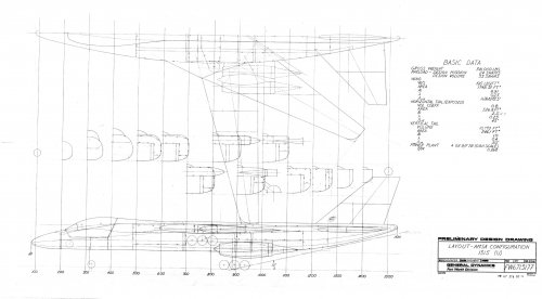
Orionblamblam said:A low rez version of this was posted before, but here's a higher rez. A higher-rez-yet version is at my blog:
http://up-ship.com/blog/?p=11430
Also attached is a blowup of the "subsonic" model. And it actually does seem to say "subsonic." A few possible explanations:
1: Circle-5 actually has this model, which was mislabeled
2: NAA made a number of mis-labeled models
3: This was actually meant to be subsonic
1& 2 look less likely now, but #3 just seems silly.
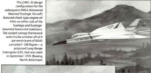
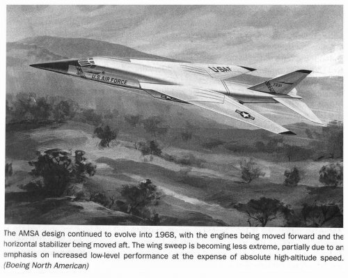
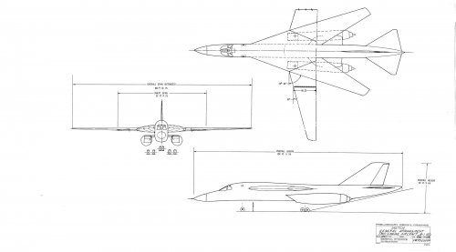
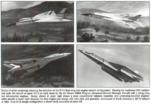
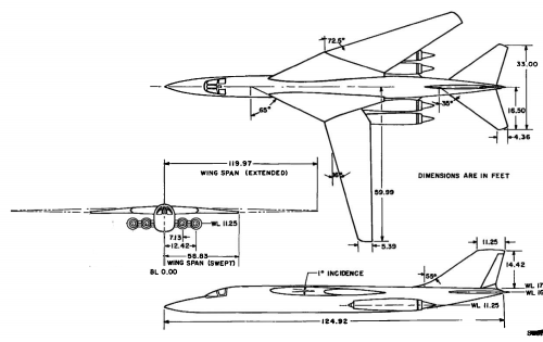
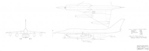
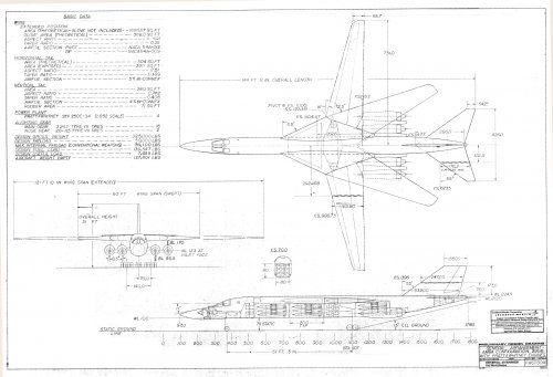
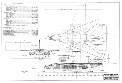
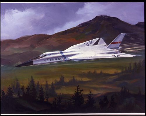
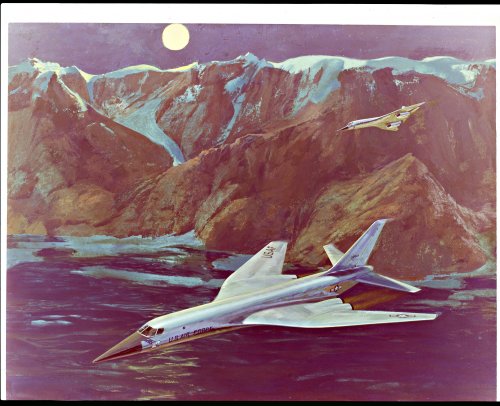
The final AMSA development (the B-1B) has an impressive VG wing design, yet its mission is typically subsonic, with only marginal supersonic capability. I don't feel these characteristics need to be mutually exclusive, although the Subsonic AMPSS is indeed a bit much.
I only know of one example each of the models featured here, but if others appear with the same subsonic stand, then we'll definitely know it's subsonic. Even if initially mis-labeled, such models would have never made it into NAA PR and historical photographs without correction.
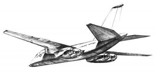
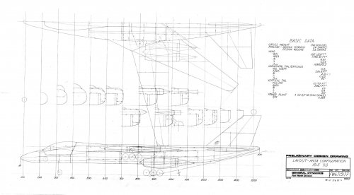
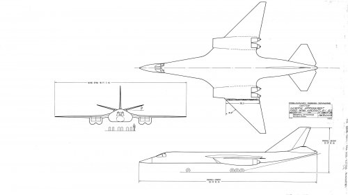
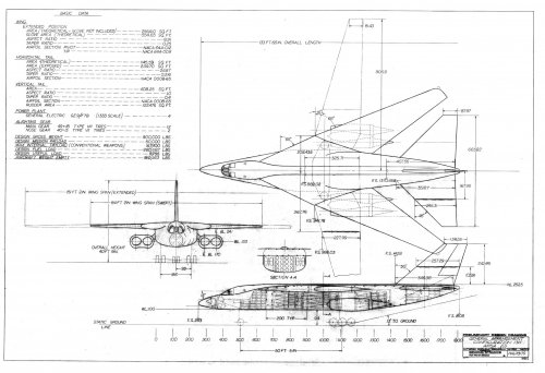
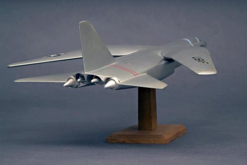
Attached is a rarely seen rear view of the big NAA AMPSS VG model, showing its unusual engine arrangement and gullwing appearance.
(Model photo © by Chad Slattery)
")