
- Joined
- 11 February 2010
- Messages
- 1,445
- Reaction score
- 1,940
Greetings. As the title said, here i would like to present and discuss about a simplified approach to approximate detection range of an IRST.
I feel that this is a necessary topics mainly because so far, no real quantitative comparison or even discussion exist. Every Optical sensor equipment manufacturer usually only mention range without having a real standard on what target being used and testing environment.
Standardized target and environment is i see of a paramount importance if we wish to say or compare if product from A is better than B. Another problem is scarcity of information as we see no one really disclose the necessary variables like the specific detectivity of their respective detector element. Therefore i view that, despite the availability of the full equation. The approach must be :
1.Simple and can work with what is available to the user
2.Robust, means that it allows wide coverage, say estimating target infra red signature in any IR band of choice.
3.Easily run in any platform having spreadsheet capability without requiring any special add ons (well gotta admit i might need to learn how to use Google spreadsheet)
The method i am using here is basically a simplified version of IR range equation presented in E.Fleeman's Tactical missile design 2nd edition. The simplified method, as like one you may see on Radar relies on inverse square law and require a reference value to work with. Here i would like to use the new OLS-35, as reference. Why ? As we see in the brochure it has range figure and a reference target.
the image is just too big so i guess a link is sufficient
https://defenseissues.files.wordpress.com/2013/12/qrkpwi.jpg
The establishment of the required variables follows the following steps :
1.Finding relevant data and establish the assumption for both target and the IRST sensor.
2.Estimate the target signature (Radiant intensity) In the working band of the IRST
3.Estimate the environment factor (Transmittance of working waveband of the IRST)
4.Calculate the new detection range based on the reference value established in num 1 procedure
and a bit of detail on each steps :
1.Finding relevant data and establish the assumption for both target and the IRST sensor.
Here we will use one example of OLS-35. Which have following data :
Range
Frontal aspect : 50 Km
Rear aspect : 90 Km
Working waveband : about 8-12 micron
Reference target : Su-30.
The assumption is as follows :
1.Altitude of 12000 meters
2.Atmospheric Transmission of 90-100%
3.Frontal area is assumed. Thus expected signature is coming from the kinetic friction between the airframe and surrounding air
4.TAS of M 0.9
Now we wish to calculate the range of the OLS against an F-22 Raptor
Since the radiant intensity or the intensity of the target of an IRST system related directly to the exposed area
and temperature of the target, those two variables are of paramount importance. Thus we will start by first making a
relevant measurement to obtain the area of both target and the reference system. The calculation for the area of target
is detailed in the "how to use" sheet in the spreadsheet. Which yield the following result :
Su-30 exposed area : 7.6886 Sqm
F-22 Raptor exposed area : 5.8114 sqm
One may ask on why i only include the fuselage area. This is because of the resolution of available imagery does not seem to be enough to conduct a more accurate assessment. Plus there are no real easy method to include or measure the projected area of the wing which need wing thickness. information which would be difficult to obtain. I consider that the fuselage alone would be sufficient.
For the calculation of detection range from the rear aspect. The IRST is assumed to be "snooping" inside the jetpipe. and the area of the infra red emmission source would be assumed to be the sum of the jetpipe frontal area.
Now that we have established the assumption and necessary variables. we can head to the 2nd step.
2.Estimate the target signature (Radiant intensity) In the working band of the IRST

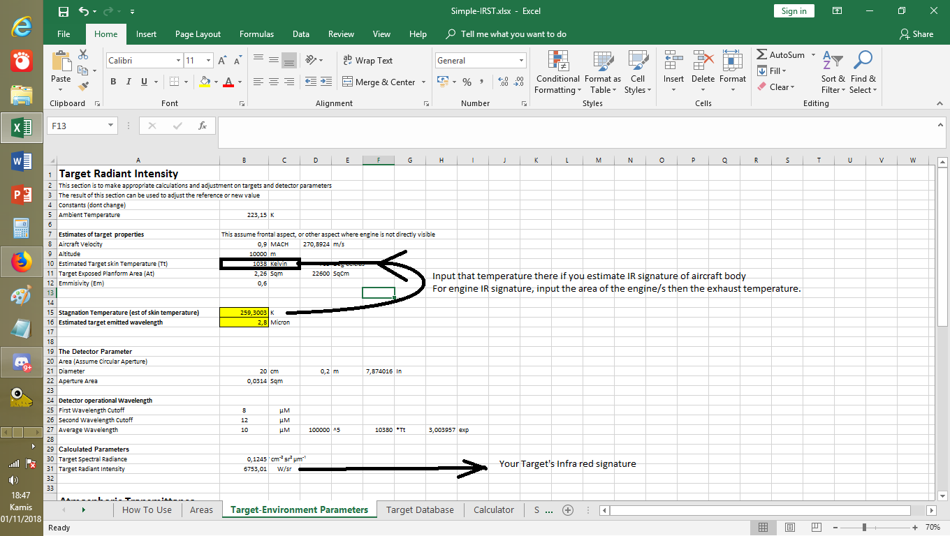
Now we need to estimate the Radiant intensity or the intensity of the energy being emitted by target on the operating wavelength of the IRST.
Here at the sheet above, you can start inputting variables like your flight speed, altitude, target exposed area and the emissivity. The recommended way to do it. Assuming that you wish to estimate target skin temperature (Not engine) Is by first input the target altitude, speed and the exposed planform area. The emissivity variable has been selected to be typical of aircraft paint, with some light gray color. You can change it to whatever suits you. Lighter color/polish will tend to have lower emissivity but highly reflective
and vice versa.
Should you wish to estimate engine jetpipe emission, you can just directly input the temperature of the exhaust temperature (The exhaust temperature here is defined right after Turbine outlet) The emissivity parameter is by default 0.6 as i dont really know what value i should use, probably 0.9 or more as the aircraft engine inside are clearly not reflective.
The second thing after inputting the necessary variable would be defining the working waveband of the IRST at "Detector Operational Wavelength" Here you can define the first cutoff of operating wavelength and the 2nd one. OLS-35 is known to have operating wavelength of 8-12 micron. Thus 8 is the first cutoff while the 2nd cutoff would be 12. Same if the detector operates in more wavelength Say 4-12 (covering both mid and long wave IR).
A target table that contains the pre-calculated value are also available. You can manually add your own target, just make sure to type the necessary assumption regarding flight speed and altitude.
If one desire to calculate the IR signature from the rear, one simply need to enter the jetpipe temperature and the area of the engine rear face as input. If there is two engines, the area is basically both engine added.
After calculating or selecting the necessary value of IR signature (Reference and target). We can move to the 3rd step. The atmospheric.
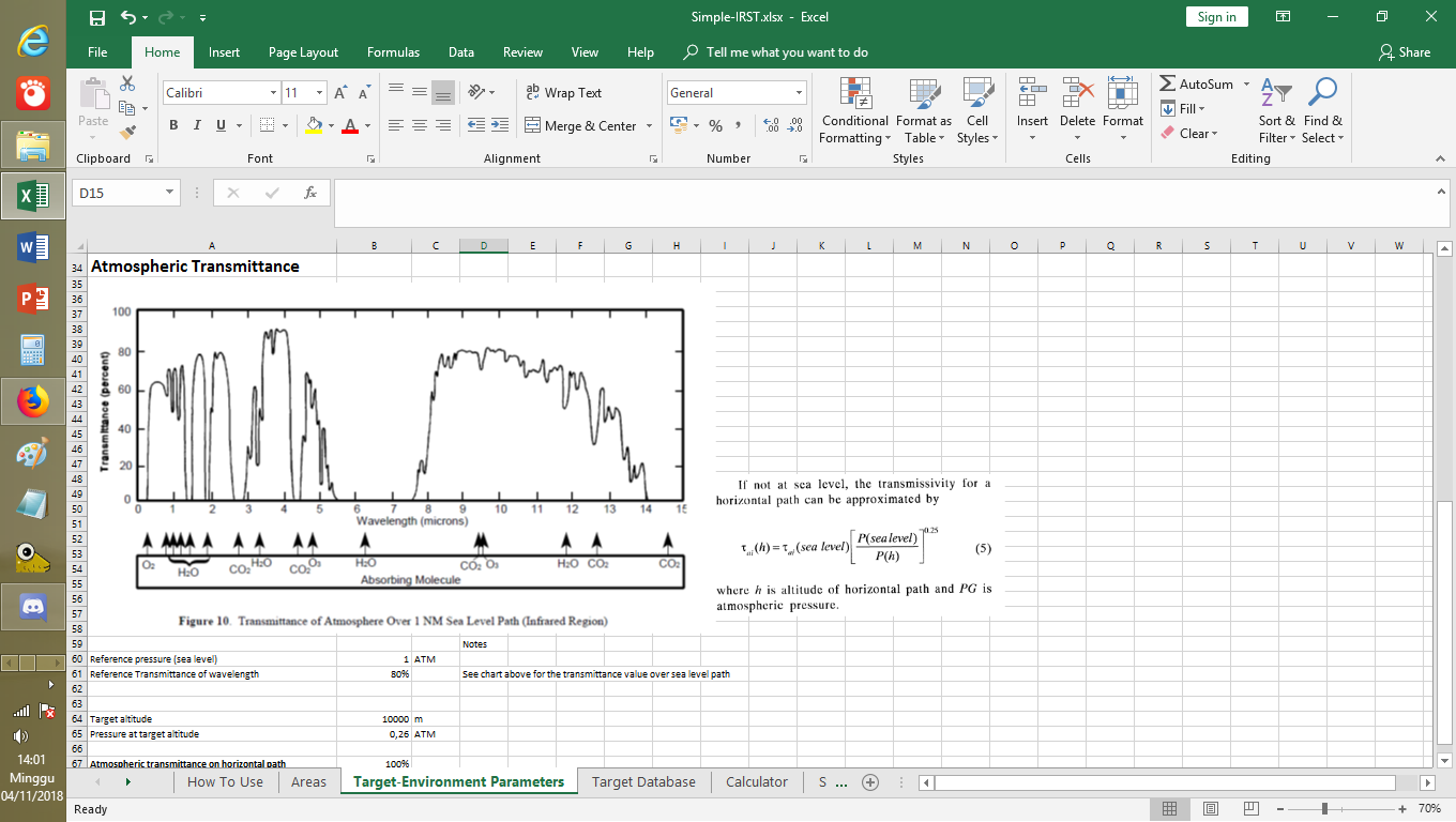
3.Estimate the environment factor (Transmittance of working waveband of the IRST)
The method contained in spreadsheet is unfortunately only based on Gas as main "absorbent" for the IR wavelength. However for early approximate it should be adequate. The spreadsheet contained a chart with sea level transmittance value of IR wavelength. The altitude parameter here is tied to the altitude column (at the moment as i am still developing this sheet).
The simple sheet here will help you to estimate probable transmission of IR wavelength of your respective IRST based on altitude and reference value. The way you do that is just see the chart, draw value of your IRST working wavelength and put it in "Reference Transmittance of Wavelength" . The chart is based on sea level altitude. The target altitude is assumed to be the same as the one you inputted in the Target radiant intensity
Finally the value can be read on the coloum "Atmospheric transmittance on horizontal path".
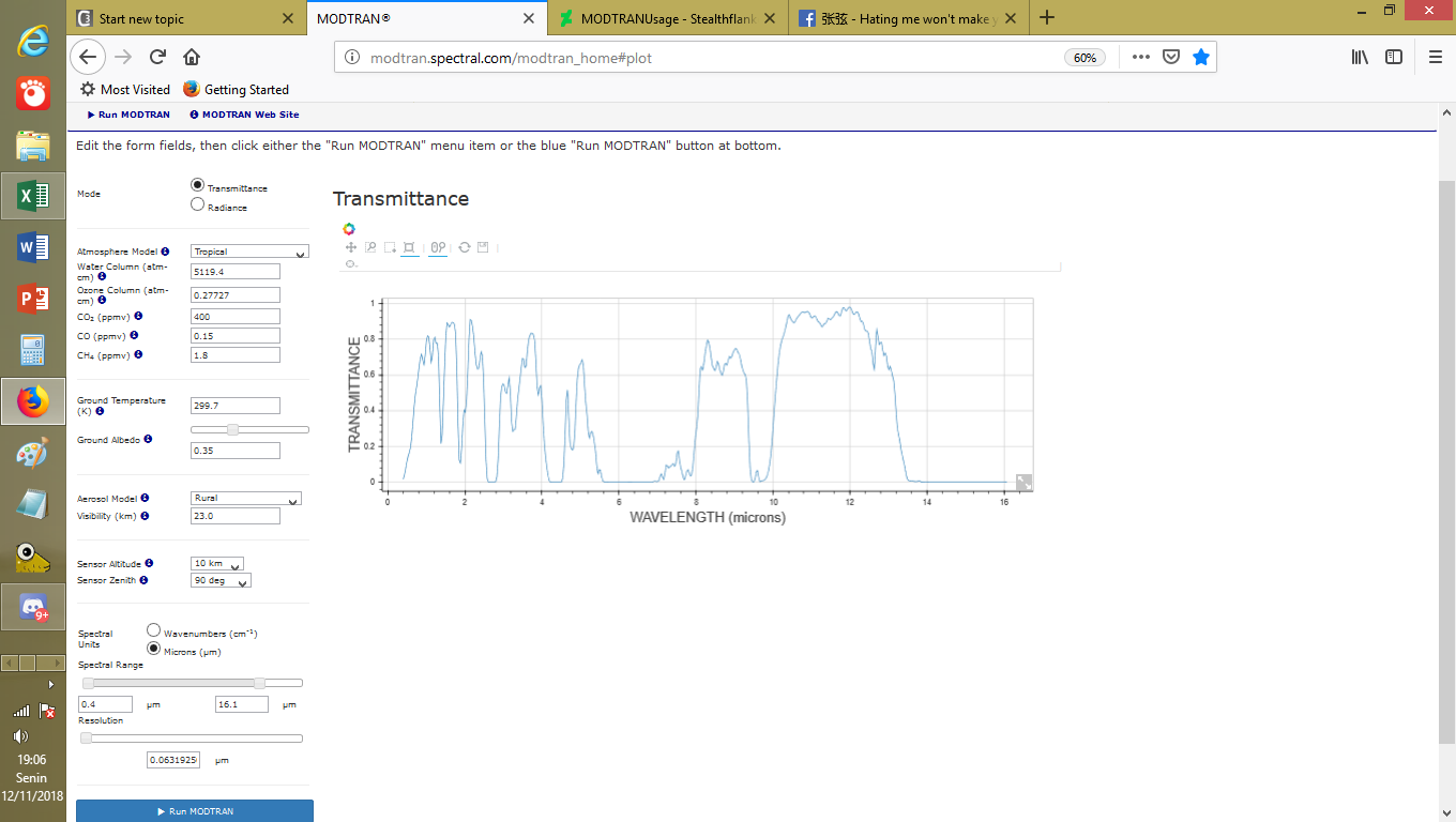
More powerful way to estimate the transmittance factor would be by using the MODTRAN web-app
http://modtran.spectral.com/modtran_home
It allows for multiple environment factors and other variables not covered in the sheet. Regarding usage, there is one convention namely angle of view (sensor zenith). 90 degrees appears to be suitable for the aircraft, while larger values are more suitable for ground targets or reconnaissance satellite purpose.
The convention.
https://orig00.deviantart.net/8e32/f/2018/315/5/4/modtranusage_by_stealthflanker-dcrshls.png
Example usage and result
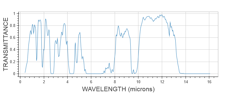
The resulting chart.
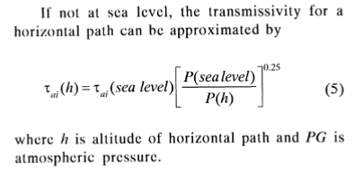
And someone may ask "Hey isnt that for 10000 m altitude while your reference value is for 12000 m ?" Then we can use the following equation to estimate the value. Except that now it use the 10000 m as reference.
Where P is pressure and the greek alphabet Tau denotes the reference altitude's transmittance factor.
Anyway following the steps outlined above we managed to obtain the following information :
Reference Transmittance value :100%
Transmittance value at selected altitude : 100%
Basically a co-altitude situation.
The final step :
4.Calculate the new detection range based on the reference value established in num 1 procedure
This is the final step namely the range calculation. From step 1-3 we have successfully (hopefully) established the following :
Reference Value for OLS-35 Data.
IRST Aperture Area : 0,0314 sqm
Reference Spectral Radiance : 190,16 W/sr
Reference Atmospheric Transmittance : 100%
Reference Range: 50 Km
Above value is valid for 12000 meter. Now we wish to estimate the performance of the same IRST but against F-22 Raptor. At same altitude and cruising at M 0.9
Repeating the step 1-3 for Raptor yield the following data :
Range based on new parameter
IRST Aperture Diameter: 0,2 m or Area: 0,031415927 sqm
New Atmospheric transmittance: 100%
Radiant Intensity of Target: 143,72 W/sr
Then we can read the range column and we see range against the F-22 Raptor cruising at M 0.9 at altitude of 12000 m is about 43 km
How about if we wish to estimate the range against supercruising F-22 raptor at M 1.6 ? We repeat the 1-3 procedure and found that
the emitted radiant intensity would be about 567.33 W/sr. We enter the new value of the radiant intensity to the appropriate coloum
and found the detection range to be about 86,39 km.
Now one might wish to make a "what if" scenario on "how about if i can enlarge the IRST how far it can enhance range ?" one can simply change the IRST aperture diameter at "IRST Aperture Diameter" coloumn to the value of his desire. In this scenario we choose to "enlarge" the OLS-35 optical aperture to 40 cm (0.4 m) and as we see we have range of 172 Km against F-22 Raptor on Supercruise and 86 km for non supercruise mode respectively.
That is all i think i could describe for now. Hopefully this could open a new discussion and methods. The calculator can be downloaded at the end of this post. Wish you all have a great time ;D
DOWNLOAD SPREADSHEET :
https://www.mediafire.com/file/bvt80goe445kdba/Simple-IRST-Exp.xlsx/file
I feel that this is a necessary topics mainly because so far, no real quantitative comparison or even discussion exist. Every Optical sensor equipment manufacturer usually only mention range without having a real standard on what target being used and testing environment.
Standardized target and environment is i see of a paramount importance if we wish to say or compare if product from A is better than B. Another problem is scarcity of information as we see no one really disclose the necessary variables like the specific detectivity of their respective detector element. Therefore i view that, despite the availability of the full equation. The approach must be :
1.Simple and can work with what is available to the user
2.Robust, means that it allows wide coverage, say estimating target infra red signature in any IR band of choice.
3.Easily run in any platform having spreadsheet capability without requiring any special add ons (well gotta admit i might need to learn how to use Google spreadsheet)
The method i am using here is basically a simplified version of IR range equation presented in E.Fleeman's Tactical missile design 2nd edition. The simplified method, as like one you may see on Radar relies on inverse square law and require a reference value to work with. Here i would like to use the new OLS-35, as reference. Why ? As we see in the brochure it has range figure and a reference target.
the image is just too big so i guess a link is sufficient
https://defenseissues.files.wordpress.com/2013/12/qrkpwi.jpg
The establishment of the required variables follows the following steps :
1.Finding relevant data and establish the assumption for both target and the IRST sensor.
2.Estimate the target signature (Radiant intensity) In the working band of the IRST
3.Estimate the environment factor (Transmittance of working waveband of the IRST)
4.Calculate the new detection range based on the reference value established in num 1 procedure
and a bit of detail on each steps :
1.Finding relevant data and establish the assumption for both target and the IRST sensor.
Here we will use one example of OLS-35. Which have following data :
Range
Frontal aspect : 50 Km
Rear aspect : 90 Km
Working waveband : about 8-12 micron
Reference target : Su-30.
The assumption is as follows :
1.Altitude of 12000 meters
2.Atmospheric Transmission of 90-100%
3.Frontal area is assumed. Thus expected signature is coming from the kinetic friction between the airframe and surrounding air
4.TAS of M 0.9
Now we wish to calculate the range of the OLS against an F-22 Raptor
Since the radiant intensity or the intensity of the target of an IRST system related directly to the exposed area
and temperature of the target, those two variables are of paramount importance. Thus we will start by first making a
relevant measurement to obtain the area of both target and the reference system. The calculation for the area of target
is detailed in the "how to use" sheet in the spreadsheet. Which yield the following result :
Su-30 exposed area : 7.6886 Sqm
F-22 Raptor exposed area : 5.8114 sqm
One may ask on why i only include the fuselage area. This is because of the resolution of available imagery does not seem to be enough to conduct a more accurate assessment. Plus there are no real easy method to include or measure the projected area of the wing which need wing thickness. information which would be difficult to obtain. I consider that the fuselage alone would be sufficient.
For the calculation of detection range from the rear aspect. The IRST is assumed to be "snooping" inside the jetpipe. and the area of the infra red emmission source would be assumed to be the sum of the jetpipe frontal area.
Now that we have established the assumption and necessary variables. we can head to the 2nd step.
2.Estimate the target signature (Radiant intensity) In the working band of the IRST
Now we need to estimate the Radiant intensity or the intensity of the energy being emitted by target on the operating wavelength of the IRST.
Here at the sheet above, you can start inputting variables like your flight speed, altitude, target exposed area and the emissivity. The recommended way to do it. Assuming that you wish to estimate target skin temperature (Not engine) Is by first input the target altitude, speed and the exposed planform area. The emissivity variable has been selected to be typical of aircraft paint, with some light gray color. You can change it to whatever suits you. Lighter color/polish will tend to have lower emissivity but highly reflective
and vice versa.
Should you wish to estimate engine jetpipe emission, you can just directly input the temperature of the exhaust temperature (The exhaust temperature here is defined right after Turbine outlet) The emissivity parameter is by default 0.6 as i dont really know what value i should use, probably 0.9 or more as the aircraft engine inside are clearly not reflective.
The second thing after inputting the necessary variable would be defining the working waveband of the IRST at "Detector Operational Wavelength" Here you can define the first cutoff of operating wavelength and the 2nd one. OLS-35 is known to have operating wavelength of 8-12 micron. Thus 8 is the first cutoff while the 2nd cutoff would be 12. Same if the detector operates in more wavelength Say 4-12 (covering both mid and long wave IR).
A target table that contains the pre-calculated value are also available. You can manually add your own target, just make sure to type the necessary assumption regarding flight speed and altitude.

If one desire to calculate the IR signature from the rear, one simply need to enter the jetpipe temperature and the area of the engine rear face as input. If there is two engines, the area is basically both engine added.
After calculating or selecting the necessary value of IR signature (Reference and target). We can move to the 3rd step. The atmospheric.
3.Estimate the environment factor (Transmittance of working waveband of the IRST)
The method contained in spreadsheet is unfortunately only based on Gas as main "absorbent" for the IR wavelength. However for early approximate it should be adequate. The spreadsheet contained a chart with sea level transmittance value of IR wavelength. The altitude parameter here is tied to the altitude column (at the moment as i am still developing this sheet).
The simple sheet here will help you to estimate probable transmission of IR wavelength of your respective IRST based on altitude and reference value. The way you do that is just see the chart, draw value of your IRST working wavelength and put it in "Reference Transmittance of Wavelength" . The chart is based on sea level altitude. The target altitude is assumed to be the same as the one you inputted in the Target radiant intensity
Finally the value can be read on the coloum "Atmospheric transmittance on horizontal path".
More powerful way to estimate the transmittance factor would be by using the MODTRAN web-app
http://modtran.spectral.com/modtran_home
It allows for multiple environment factors and other variables not covered in the sheet. Regarding usage, there is one convention namely angle of view (sensor zenith). 90 degrees appears to be suitable for the aircraft, while larger values are more suitable for ground targets or reconnaissance satellite purpose.
The convention.
https://orig00.deviantart.net/8e32/f/2018/315/5/4/modtranusage_by_stealthflanker-dcrshls.png
Example usage and result
The resulting chart.
And someone may ask "Hey isnt that for 10000 m altitude while your reference value is for 12000 m ?" Then we can use the following equation to estimate the value. Except that now it use the 10000 m as reference.
Where P is pressure and the greek alphabet Tau denotes the reference altitude's transmittance factor.
Anyway following the steps outlined above we managed to obtain the following information :
Reference Transmittance value :100%
Transmittance value at selected altitude : 100%
Basically a co-altitude situation.
The final step :
4.Calculate the new detection range based on the reference value established in num 1 procedure
This is the final step namely the range calculation. From step 1-3 we have successfully (hopefully) established the following :
Reference Value for OLS-35 Data.
IRST Aperture Area : 0,0314 sqm
Reference Spectral Radiance : 190,16 W/sr
Reference Atmospheric Transmittance : 100%
Reference Range: 50 Km
Above value is valid for 12000 meter. Now we wish to estimate the performance of the same IRST but against F-22 Raptor. At same altitude and cruising at M 0.9
Repeating the step 1-3 for Raptor yield the following data :
Range based on new parameter
IRST Aperture Diameter: 0,2 m or Area: 0,031415927 sqm
New Atmospheric transmittance: 100%
Radiant Intensity of Target: 143,72 W/sr
Then we can read the range column and we see range against the F-22 Raptor cruising at M 0.9 at altitude of 12000 m is about 43 km
How about if we wish to estimate the range against supercruising F-22 raptor at M 1.6 ? We repeat the 1-3 procedure and found that
the emitted radiant intensity would be about 567.33 W/sr. We enter the new value of the radiant intensity to the appropriate coloum
and found the detection range to be about 86,39 km.
Now one might wish to make a "what if" scenario on "how about if i can enlarge the IRST how far it can enhance range ?" one can simply change the IRST aperture diameter at "IRST Aperture Diameter" coloumn to the value of his desire. In this scenario we choose to "enlarge" the OLS-35 optical aperture to 40 cm (0.4 m) and as we see we have range of 172 Km against F-22 Raptor on Supercruise and 86 km for non supercruise mode respectively.
That is all i think i could describe for now. Hopefully this could open a new discussion and methods. The calculator can be downloaded at the end of this post. Wish you all have a great time ;D
DOWNLOAD SPREADSHEET :
https://www.mediafire.com/file/bvt80goe445kdba/Simple-IRST-Exp.xlsx/file