Canadair business aircraft projects

Stargazer

ACCESS: USAP
Senior Member
Joined
25 June 2009
Messages
13,745
Reaction score
2,931
Canadair Executive Aircraft Design History
by Bill Upton

Many of the proposed, new passenger transport designs, that came from the Canadair engineering mindset, catered mainly to the larger military market. If purchased by the military they would have a greater chance of being adapted for sales, at lower prices, in the civilian market. Some of these design proposals for propeller and jet driven aircraft were also marketed as corporate executive and business types, and a few made it to the mock-up stage and, in some cases, metal was cut for proposed contracts.
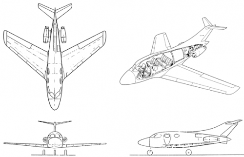
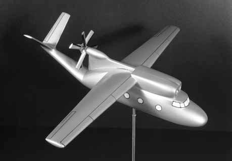
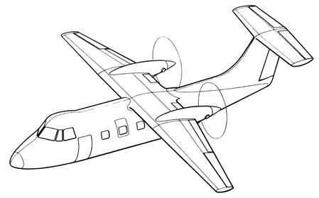
A few of the Canadair models that reached an advanced study, drawing or hardware stage for a business/executive transport aircraft included the CL-60/CL-42, CL-41, CL-53, CL-69 and CL-95.

NOTE: The CL-15, CL-15A, CL-42 and CL-60 series is covered in a separate topic:
USAF T-36A trainer (Beechcraft Model 46 / Canadair CL-60)
 
CL-41 Business Executive Transport

Canadair undertook a somewhat risky move in mid-1955 to design and manufacture a side-by-side seating ab initio jet trainer to replace the venerable Harvard in the pilot training role for the RCAF, even though there had been no initial interest by the military in such a Canadian made concept. It was felt that this design showed promise and Canadair decided to proceed to construct two prototype aircraft under the assigned Canadair model number CL-41. A full-scale engineering mockup, in pseudo military markings, was constructed in 1957, and this was later modified and repainted to represent a potential civilian CL-41 variant. This civilian version, with the interior adaptable to seat four, was suggested for use as a convenient and practical means of high-speed transportation for important officials and business executives. Nothing ever came of this proposal. However, the CL-41 jet trainer design progressed and Canadair soon received contracts for the production of 190 examples of this aircraft as the CL-41A/CT-114, Tutor trainer for the RCAF, and 20 CL-41G Tebuan light attack versions, destined for the Royal Malaysian Air Force.


Caption:
In early 1958 Canadair was marketing a serious proposal for the “Canadair Trainer 41” civil variant catering to the busy travelling executive.
 

Attachments

  • CL-41 business transport.png
    CL-41 business transport.png
    58.7 KB · Views: 426
CL-53 Business Jet Transport

The CL-53 preliminary design proposal was conceived in 1956 in anticipation of a possible USAF requirement for a crew readiness trainer and small jet transport. The design concept was also readily adaptable for a small business jet type of transport. The basic CL-53 design would utilize many of the major components and tooling from the F-86 Sabre aircraft, which was still being manufactured at the time by Canadair as the famed CL-13 model series. The aim of this was to benefit from proven operational serviceability of these components and to reduce costs and aircraft developmental lead-time. Parts commonality between the CL-13 and CL-53 included the complete wings, the horizontal “all-flying” tailplane, landing gear, the hydraulics and some electrical systems. The aircraft would seat seven and was to be powered by three 8.90 kN (2,000-pound) thrust Rolls Royce RB-108 or Fairchild J83 jet engines. Two engines were to be mounted on the outside rear fuselage in nacelles and one enclosed in the rear fuselage. The intakes for the interior engine were to be located on the sides of the rear fuselage and incorporated doors that could be closed when the engine was not in use to improve cruise performance. All three engines would be equipped with thrust reversers. This concept remained only in the preliminary design phase.


Caption:
These three-view and perspective cutaway drawings of the CL-53 reveal something vaguely familiar in its design origins. This concept incorporating the T-tail and rear fuselage mounted engines would unknowingly become beneficial to another Canadair business jet later on.
 

Attachments

  • CL-53 business transport.png
    CL-53 business transport.png
    80.3 KB · Views: 257
CL-69 Business and Utility Executive Transport

A truly interesting concept, the CL-69 was by no means a pretty airplane. This business and executive transport configuration, either land or water based, was designed in June 1958 as a twin engine turboprop, high cantilever wing, monoplane with somewhat short takeoff and landing (STOL) performance. For the amphibious operations, a separate boat-like hull equipped with stub wings and retractable, tricycle-type wheeled gear could be readily attached underneath the main fuselage.

This 600 shaft-horsepower, twin-engine aircraft, would employ both engines for takeoff and then could convert to single engine operation for the cruise portion of flight, capable of achieving a maximum speed of 296 knots (547 km/h / 340 mph). It would seem that the side-by-side engine grouping, mounted immediately above the cockpit and cabin, might have caused some discomfort to the passengers and crew. A choice of a single pusher propeller, or two contra-rotating pusher propellers, driven by common driveshafts, was made available.

Seating capacity was to be seven passengers and a crew of two. It had a length of 12.19 m (40 ft), a height of 4.87 m (16 ft) with a 15.24 m (50 ft) wing span, and weight of 3,628.8 kg (8,000 lbs). Like many of its contemporaries, it did not proceed beyond a study phase.


Caption:
This 1959 model depicts the odd-looking CL-69 in a land-based configuration with dorsal pusher contra-rotating propellers at the rear above the upswept tail boom. The large round cabin windows on each side of the fuselage are strangely reminiscent of ship portholes.
 

Attachments

  • CL-69 business and utility executive transport.jpg
    CL-69 business and utility executive transport.jpg
    13.1 KB · Views: 243
CL-95 Turboprop Executive Aircraft

The CL-95, a May 1961 design study, encompassed four main variations of a twin-engine turboprop, T-tailed, executive and business type aircraft. The different designs envisioned either a circular or elliptical shaped fuselage cross section, high or low wing arrangement, and multiple configurations of engine mounting, with the tractor or pusher propellers mounted below, within or above the wing. Power was to be provided by dual Canadian Pratt & Whitney PT6-A turboshaft engines, rated at 500 shaft-horsepower as the preferred choice, with two Continental T-72s slated as alternatives. The preferred pusher propeller and high wing arrangement had some advantages, most notably more propulsive efficiency than the tractor type, and placing the annoying propeller noise behind the main cabin. This arrangement also provided forward, unobstructed aircraft access by passengers with engines running. The dual main gear could be retracted rearward into the unpressurized tail cone, instead of into the engine nacelles. It was to have a fuselage length of 13.56 m (44 ft 6 in), height of 3.50 m (11 ft 6 in) and wing span of 13.56 m (44 ft 6 in).
This variant of the CL-95 would be capable of carrying 6 to 8 passengers and a crew of two, with a gross weight of 4,080 kg (9,000 lbs) over a 1,850 km (1,160 miles) distance at 260 knots (482 km/h / 300 mph).
Once again, there was no further progress beyond the study phase, but with each successive design, tradition and valuable design experience was gained for future reference.


Caption:
This drawing depicts the high wing with pusher propeller version of the CL-95 executive aircraft.
 

Attachments

  • CL-95 turboprop executive aircraft.png
    CL-95 turboprop executive aircraft.png
    40.2 KB · Views: 224
CL-53 Business Jet Transport

The CL-53 preliminary design proposal was conceived in 1956 in anticipation of a possible USAF requirement for a crew readiness trainer and small jet transport. The design concept was also readily adaptable for a small business jet type of transport. The basic CL-53 design would utilize many of the major components and tooling from the F-86 Sabre aircraft, which was still being manufactured at the time by Canadair as the famed CL-13 model series. The aim of this was to benefit from proven operational serviceability of these components and to reduce costs and aircraft developmental lead-time. Parts commonality between the CL-13 and CL-53 included the complete wings, the horizontal “all-flying” tailplane, landing gear, the hydraulics and some electrical systems. The aircraft would seat seven and was to be powered by three 8.90 kN (2,000-pound) thrust Rolls Royce RB-108 or Fairchild J83 jet engines. Two engines were to be mounted on the outside rear fuselage in nacelles and one enclosed in the rear fuselage. The intakes for the interior engine were to be located on the sides of the rear fuselage and incorporated doors that could be closed when the engine was not in use to improve cruise performance. All three engines would be equipped with thrust reversers. This concept remained only in the preliminary design phase.


Caption:
These three-view and perspective cutaway drawings of the CL-53 reveal something vaguely familiar in its design origins. This concept incorporating the T-tail and rear fuselage mounted engines would unknowingly become beneficial to another Canadair business jet later on.

As an aside, how many F-86 fighter components were used in North American Sabreliner business jets?
 
CL-69 Business and Utility Executive Transport

A truly interesting concept, the CL-69 was by no means a pretty airplane. This business and executive transport configuration, either land or water based, was designed in June 1958 as a twin engine turboprop, high cantilever wing, monoplane with somewhat short takeoff and landing (STOL) performance. For the amphibious operations, a separate boat-like hull equipped with stub wings and retractable, tricycle-type wheeled gear could be readily attached underneath the main fuselage.

This 600 shaft-horsepower, twin-engine aircraft, would employ both engines for takeoff and then could convert to single engine operation for the cruise portion of flight, capable of achieving a maximum speed of 296 knots (547 km/h / 340 mph). It would seem that the side-by-side engine grouping, mounted immediately above the cockpit and cabin, might have caused some discomfort to the passengers and crew. A choice of a single pusher propeller, or two contra-rotating pusher propellers, driven by common driveshafts, was made available.

Seating capacity was to be seven passengers and a crew of two. It had a length of 12.19 m (40 ft), a height of 4.87 m (16 ft) with a 15.24 m (50 ft) wing span, and weight of 3,628.8 kg (8,000 lbs). Like many of its contemporaries, it did not proceed beyond a study phase.


Caption:
This 1959 model depicts the odd-looking CL-69 in a land-based configuration with dorsal pusher contra-rotating propellers at the rear above the upswept tail boom. The large round cabin windows on each side of the fuselage are strangely reminiscent of ship portholes.

That V-tail looks way too small especially considering all the extra (de-stabilizing) side area ahead of the wing.
 
CL-95 lines remind us of deHavilland's later Dash 8 commuter plane.

CL-95 cockpit was definitely an after-thought cludged on by a British engineer.
Ugh!
 

Similar threads

Back
Top Bottom