5 CONCLUSIONS
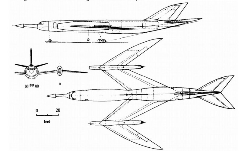
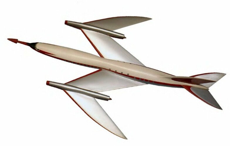
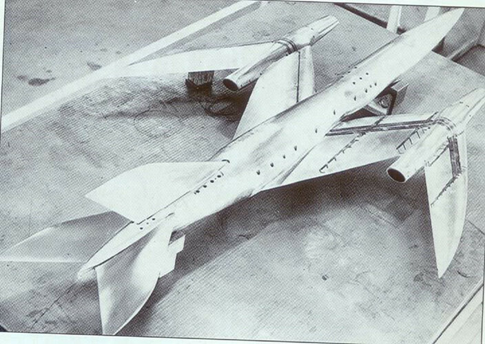
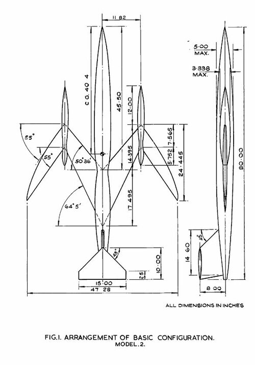
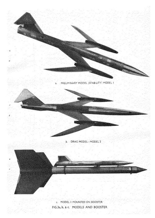
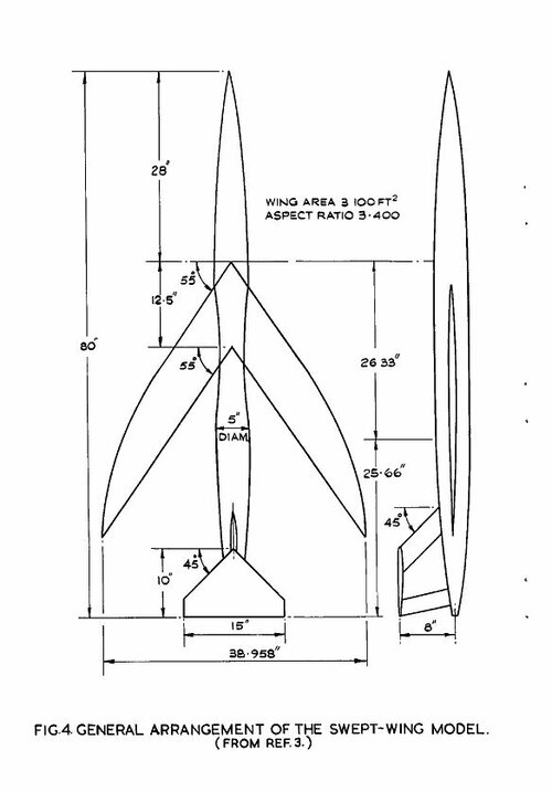
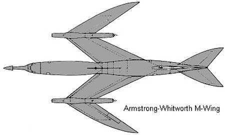
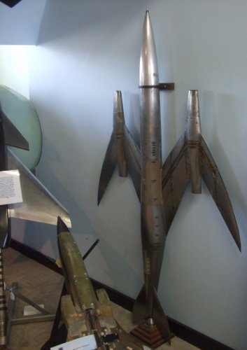
Free-flight tests have been made on two models of an M-wing aircraft configuration, deslgned to maintain a subsonic type of flow over the ning surfaces with no shook waves occurring on the wings, at speeds up to a Mach number of 1.3. Results on the longitudinal stability elf the configuration have been obtained from a simplified preliminary model and measurements of the total drag and the wing root pressure distribution were made on a second fully representative model. From these latter results it has proved possible to deduce that the design principles have been achieved. Comparisons with results from freeflight tests on a swept-wing configuration designed in a similar way have been made.
The main conclusions are:-
(1) The pressure measurements in the wing root, although partially unsuccessful, were adequate to show at the highest Mlach numbers that a subsonic type of flow was established there and that no evidence of shook waves existed.
(2) The zero-lift wave drag of the wing-body-nacelle combination has been evaluated from the measured total drag by subtracting the contributions from skin friction and the fin and tailplane, and is shown to be lower than that of the sum of the wave drags of the components in isolation. This indicates that some suppression of the wing wave drag expected from the design has occurred. It is not possible to calculate the body and nacelle drag as installed; so one cannot deduce whether all the wing wave drag was suppressed,
(3) The wave drag factor K is 2.4 at the design Mach number of 1'2. This is considered reasonably low for a first attempt at such a configuration. It is roughly twice that of a comparable swept-wing-body combination but the contribution from the nucolles that are included in the M-wing drag factor is probably responsible for the major part of this increase.
(4) The M-wing model has a somewhat higher lift-curve slope than the sweptwing model owing to its higher aspect ratio. The shift in aerodynamic centre position through transonlc speeds was about 0'1 s compared with 0'2 s for the swept-wing model. If subsequent tests confirm this latter result the easing of the problem of trimming that it implies could prove to be an important additional advantage of the M-wing design.
(5) No undesirable damping characteristics in the damping-in-pitch were observed betuecn M = 0.95 - 1.3.


")