Summary
The full scale pulse jet tests have been temporarily halted because of the termination of the contract for the test site at Dover, New Jersey, and because of the necessity of modifying the JB-2 for better control in starting and stopping.
These modifications, together with a mobile thrust stand trailer, are almost complete.
Several water and smoke analogue devices for the study of compressible and non-compressible non-steady flow inside pipes and from pipe ends have been constructed. Work is proceeding on a mechanical analogue for aero-thermodynamics.
Experimental
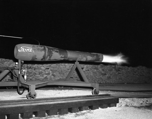
FULL SCALE PULSE JET TESTS. Several more night tests of the PJ-31 engine at Reaction Motors, Inc., in Dover, New Jersey, were made in July to determine a suitable design for pyrex windows to cover the holes drilled along the pulse jet tube. A design which shows promise of withstanding the heat and pressure was evolved and will be tested when operations are renewed. Figure 6 shows a sequence of high-speed photographs of the flames at the exhaust end of the PJ-31 engine, covering a single cycle (1/40 second) of its operations.
One effect of the absence of windows covering the holes drilled along the sides seems to be the flaming vortex which appears at the beginning and end of the cycle shown. Another effect is the more or less continuous burning within the tailpipe, shown by the luminous spots in the photograph.
On 31 July 1947, the contract with Reaction Motors, Inc., was terminated and on 1 August the JB-2 and its supporting equipment was moved to the University Heights Campus.
MODIFICATIONS OF THE JB-2. During the rest of this quarter certain modifications of the fullscale pulse jet engine and its control apparatus were proposed and are now almost completed.
This new system, first suggested to us by Lieut. J. M. Simpson, U.S.N., of Point Mugu, California, is arranged so that the control system can be operated from a remote point through a switch bank and solenoid valves. The starting air and fuel meter air have been separated to permit internal purging and pre-loading of air in the engine tube.
Under the new arrangement all the solenoid valves and controls are mounted inside the bomb fuselage.
The only outside connections are the 200 p.s.i. air supply, the 24 volt power supply, and the cable of five lines to the control board. This new setup will permit safety of operation and better control, and during bad weather it will permit the operators to be in a shelter while operating the engine. The changed air-fuel system is expected to permit a higher percentage of good starts and less danger of fire from delayed purging of unburned fuel.
THRUST STAND FOR FULL-SCALE TESTS. The design for the full-scale thrust stand was completed early in August and bids were taken. The complete bids were too high so the job was broken into segments and new bids were let. The machining work is being done by L. C. Eichner Instruments of Bloomfield, New Jersey, and is about half completed. The structural steel parts are being fabricated by the Peerless Iron Works of the Bronx, and we intend to do the assembly work ourselves. It is hoped to have the thrust stand completed, the modified JB-2 mounted on it, and both mounted on the SCR-268 trailer, as shown schematically in Figure 7, some time in November.
More in the online PDF: QUARTERLY PROGRESS REPORT - PROJECT SQUID - I OCTOBER 1947