- Joined
- 27 December 2005
- Messages
- 16,415
- Reaction score
- 18,962
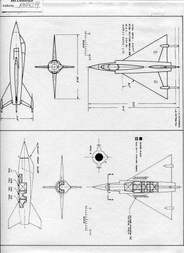
During the 1954-1957 time period Ryan engaged in four major studies which produced VATOL aircraft designs designated Model 84 (and 84F-7, a turbofan version of 84), 112, 115 and 115C. The 84 and 84F-7 were preliminary Light Day Fighter designs deriving from a broad study of a number of different VATOL configurations. Model 112 was a detailed design study of a "Visual" fighter based on the Model 84. Models 115 and 115C essentially were redesigns of the Model 112 to meet new Air Force requirements for a Dispersed Site Fighter-Bomber. All used various versions of the General Electric engines (J-79 and others with afterburning (A/B)) then under development. Models 84 (and 84F-7) and 115 were generated under Air Force contract; Ryan used their own funds for the 112 and 115C design work.
Ryan Model 84 (1954-1955): Information on the study which resulted in Model 84 was found in Reference 3.3.5.6. The effort which led to the Model 84 design started with Ryan's receipt of Air Force Contract No. AF18(600)-1157 in 1954, one of four let to industry to determine a desirable configuration of a VTOL Day Fighter. These study contracts were initiated shortly after the X-13 effort had been started and the studies were performed while it was under construction.
During their previous Navy-sponsored efforts Ryan had analyzed a wide range of VTOL approaches and concluded that the HATOL types were inferior to the VATOL ones. Further, their analyses showed the hanging (hook-suspended) VATOL aircraft to be preferable to tail-sitters including those I having a "kneeling" capability. Even after the disadvantages of pilot position dining VTOL and special ground equipment necessary were considered, the hanging type still was preferred strongly because it had the least aircraft configuration compromise, best aerodynamic cleanness, lowest empty and gross weights, and minima! jet blast effects on the ground and on trecirculation. Regarding the use of STOL capability, Ryan Aeronautical's view was expressed in Reference 3.3.5.6 by their statement: "The short runway approach to VTOL suggested in some quarters may be applicable to existing fighter types with various take-off assist and landing deceleration techniques but is wholly out of place in new designs for day fighters to be operational in 1960." In essence, in 1955 Ryan did not give serious consideration to the merits of a running take-off as a means for increasing useful load over that possible with VTO. (Later, in 1957, in an effort to satisfy Air Force desires, Ryan did design the Model 115C which incorporated an undercarriage for running take-off and landing.)
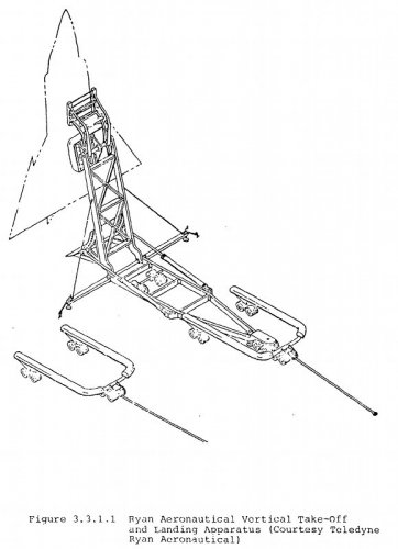
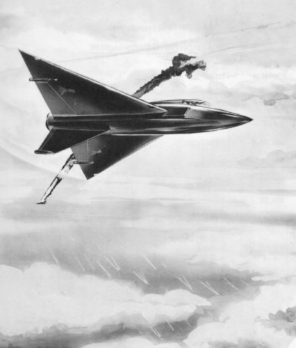
Ryan's philosophy was to design the VTOL fighter primarily for the airborne phases of the combat mission, keeping the compromises for take-off and landing to a minimum. The airframe weight saved (landing gear, wing flaps. etc.) was put into the additional propulsion needed by the VTOL fighter. The company concluded that this approach would permit the development of VTOL Light Day Fighters for use in the 1960's to meet the Air Force requirements shown in Figure 3.3.5.5.1. The specific approach was to use only a small, nonshock absorbing belly hook for take-off and landing. In addition, the ground rig, from which the aircraft operated, was equipped with blast deflectors which, when combined with the aircraft's height above the ground, eliminated ground blast and recirculation effects.
Ryan considered the most significant disadvantages of the hook-suspended concept to be: the logistic cost of moving the ground-based launching/landing and handling equipment and emergency landings away from the base. Based on their analysis the company believed the total life cycle costs to be lower for their hook-suspended fighter system than for VTOL aircraft which required a conventional landing gear, even after accounting for the costs of acquiring and delivering the ground apparatus into combat areas away from the U.S. Regarding emergency landings, the incidence of such during combat operations, where the ground apparatus could not be used, was estimated to be sufficiently low to outweigh the emergency landing merits of equipping the fighter fleet with conventional landing capability.
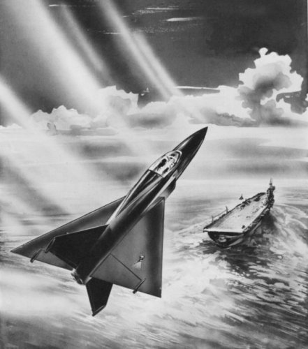
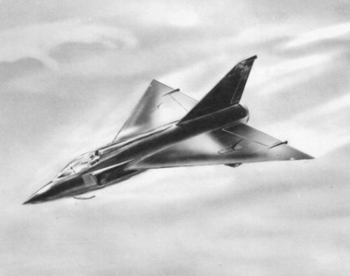
During the Model 84 study, Ryan investigated fourteen possible turbojet-powered, hook-suspended designs. Both single engine (Pratt and Whitney atterburning J-75, 23,500 lbs S.L. static thrust, 5300 lbs uninstalled weight) and twin-engine (General Electric afterburning J79-GE 14,350 lbs thrust. 3155 lbs uninstalled weight) configurations were evaluated. Since these engines were then under development, the 1955 demonstrated test stand thrust values were used. The best performing of the fourteen designs was one with side-by-side twin-engines in the fuselage, a low mounted delta wing and a conventional (tilting) seat as opposed to a prone position. Further refinement of the best of the single and twin engine designs showed the single engine to have only a 96 nmi radius of action, less than one-half of the required 200 nmi (2,000 ft. 90 deg F take-off). The twin engine design had a 219 nmi radius of action.
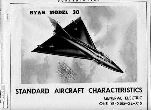
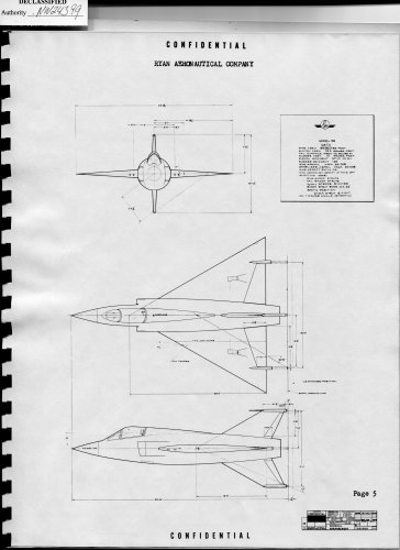
A more thorough preliminary design effort on the twin-turbojet engine aircraft followed and resulted in the Ryan Model 84, which became the basis for a follow-on detailed design, the Model 112. Both Models 84 and 112 closely resembled Model 115 (Figure 3.3.5.*.3). The characteristics of Model 84 are summarized in the previously presented Table
3.3.5.2. Features similar to those used in the Model 84; airframe aerodynamics, tilting seat. belly hook, flight controls, etc. were used in the Models 112, 115 and 115C.
In response to the Air Force interest in the potential value of the turbofan engines then being explored, Ryan also studied day fighter designs with General Electric turbofan -X84 and -X301 engines. As with the turbojet-powered designs a number of layouts (six) were made, both single and twin engine. Once agaii, the twin-turbojet,powered designs proved to be superior. Ryan proceeded to perform a preliminary design of a scaled-up version of the Model 84 (designated Model 84F-7). equipped with two General Electric -X301 turbofan engines. A significant increase in performance was obtained over the turbojet-powered Model 84; combat radius was sizeably larger and altitude capabilities greater. However, because the -X301 turbofan engine was in the early stages of development, Ryan based their subsequent VATOL efforts (Models 112, 115 and 115C) on General Electric J-79 turbojet engine derivatives.
1963 to 1966 was projected as the operational date for the -X301 engine; the J-79 was expected to be available at least 5 years earlier. Ryan believed the earlier availability of the J-79 to be of overriding importance to the introduction of VTOL day fighters into the inventory during the early 1960's. They did conclude, however, that when turbofan engines of the General at Electric -X301 class were developed. VTOL aircraft could be desioned with substantially greater capabilities than the turbojet-powered types. Based on the J-79 engine thrust and availability projections. Ryan's program analysis showed that a day fighter could be operational by 1961 if the development program was initiated during 1955.
Ryan Model 112 Visual Fighter Design
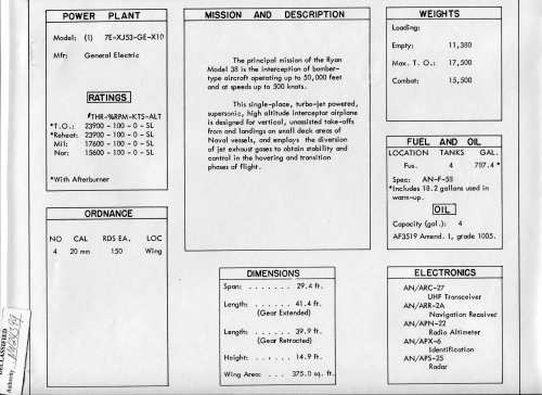
(1955-1956): As a result of the Day Fighter design study which identified Model 84 as the preferred solution, the Air Force sent a proposal request letter to Ryan (letter AC-251-3076-57) In response, Ryan undertook at their own expense an in-depth design effort based on the Model 84. The new design, now called a "Visual Fighter", designated Model 112, used two J79-GE-2 A/B engines (S.L. maximum thrust 17,000 lbs each). Aircraft weights were: empty 16,523 lbs; design VTO 26,727 (2,000 ft. 909F). Only a limited amount of information was available on the Model 112 and was found in Reference 3.3.5.7. Models 115 and 115C essentially were designs based on Model 112. Many features of Model 115 were similar to Model 112.
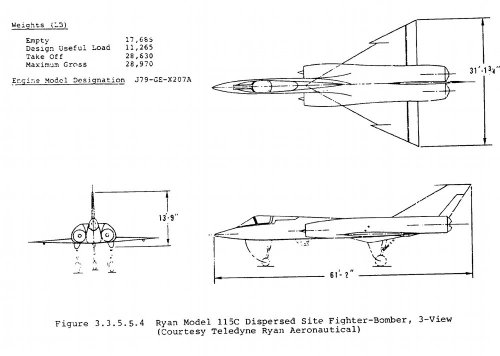
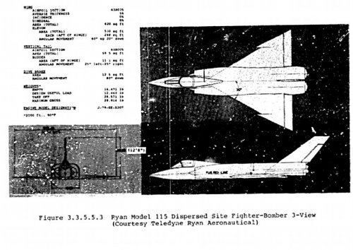
Ryan Models 115 and 115C VTOL Fighter-Bombers (1956-1957): The Model 115 design was generated under an Air Force contract study (Contract No. AF 18(600)-1641, June 1956) of a Dispersed Site Fighter-Bomber VTOL weapon system. Model 115C was a revised version of 115, somewhat larger and with more performance capability, aimed at meeting updated Air Force requirements. One version of Model 115C was equipped with a tricycle landing gear. Extensive information on Model 115 is found in Reference 3.3.5.8. which summarizes the fighter bomber study effort, and in Reference 3.3.5.9., the Model 115 Airplane Design Summary Report. Unfortunately, only a limited amount of information on the Model 115C was available and was found in Reference 3.3.5.10.
The purpose of the Dispersed Site Fighter-Bomber study was to determine if such a system could be developed for operational use in the 1960s and to formulate a development plan. Two fighter-bomber sizes were of interest; the primary one was an aircraft to provide a 450 nm radius of action (R/A) using optimum subsonic cruise. The other, a shorter range aircraft, was of lesser interest and was to be capable of 250 nm R/A. Table 3.3.5.5.1 and Figure 3.3.5.5.2 summarize the performance requirements. The aircraft were to be sized solely by the radius of action. The dash capabilities were not to enter into this sizing but were to be determined for the resulting aircraft to obtain the dash segments possible in meeting the specified radii of action.
See the source document for more details...
Source:
Bernard Lindenbaum, V-STOL Concepts and Developed Aircraft Volume 1 - A Historical Report (1940-1986)
Attachments
Last edited:
")