US IRST devices: AN/AAA-4, AN/AAS-15, AN/ALR-23

yellowaster

ACCESS: Confidential
Joined
1 January 2009
Messages
132
Reaction score
155
Does anyone have any good references on the AN/AAA-4 and AN/AAS-15 Infra-Red Search & Track sets, as used by USAF and USN in late 1950s/early 1960s ?

I believe the AAA-4 (Hughes 71N) was fitted on the F-4B; AAS-15 on the F-8D/E, F-101B and F-102A. Both used to assist with target acquisition/tracking in poor radar conditions. Googling produces a few mentions of the above but nothing substantial.

It's not entirely clear how useful these devices were. Presumably the AAA-4 was not terribly useful on the F-4 as it was not adopted for later marks.

thanks,

YA
 
In the mid / late 1960s Hughes subdivision Santa Barbara Research Center produced the 90C for the Air Force and 100C for the Navy. These may be the designation of the TDU (thermal detection unit) not the entire IRST.

We should catalog the various known US IRST devices and the planes that used them. Definitely a little-known area.


Hughes AN/AAS-15 - used in LTV F-8D/E. I have some displays and information from F-8 flight manuals for this. Will post later.
 
Last edited:
No. It was on the F8U-2N, first delivery to NavAir June 01, 1960.
The F-101B got it from 1961 on under project "Bright Horizon".
The F-102A got it under project "Big Eight" from 1963 on, even later than the F-106A, which got it under project "Big Jump" from 1961 on.
 

IRSTS - Infrared Search and Track System​

Mark Foxwell writes:
As an F-106 weapons instructor for many years at the USAF Interceptor Weapons School, we taught squadron-level weapons instructors the finer points of employing the weapons on the Six, I am here to tell you that the IRSTS, (Infrared Search and Track System) gave the Six a tremendous advantage in all combat environments. It consisted of a dome, mounted just at the forward base of the windscreen, which the pilot could extend or retract with a push of a switch on the inside of the left control stick. The dome had an infrared seeker inside that could detect and or track any IR source (the sun, any airplane recip, turbine or rocket engine, etc., etc) It would then tell the MA-1 fire control system the azimuth and elevation of the IR source. The pilot would see a spiked dot on the radar screen at the az and el of the target and would hear a distinctive tome; the tone and the spike would increase as more of the IR source was received (i.e., when you got closer). You could slave the IRSTS to the radar, in which case it would confirm a radar lockon to an IR emitting target (i.e., not chaff or ECM) or you could slave the radar to the IRSTS, so with an IR (Angle-only lockon) the radar (in sweep or track) would “see” the radar return and give the range to whatever the IR was tracking, This was especially critical when looking down at very low altitude to find a target hiding in ground clutter and also dropping chaff or blinding the radar with barrage jamming. The IRSTS was also the ONLY way to go against high altitude supersonic targets. The IRSTS would get a very strong return at as much as 180 miles away; long before the radar would see the target; then you could slave the radar to the IR and it would get the longest possible radar contact range. This was especially critical on high-closure rate front attacks (Mach 2 to Mach 3 plus combined closure rates). We were very successful at shooting down BOMARCs as drones in this environment. In short, the IRSTS IN COMBINATION WITH the radar made the Six DEADLY.

At very low altitude, when the target was lost on radar in ground clutter and/or ECM, we taught the students to do IR ANGLE-RANGING: fly down until the IR source was level then climb 1000 ft. When the new down-look angle reached 20 degrees the target was within missile range. We fired IR missiles without ever seeing the targets visually or on radar; our students had to do it from the back seat of a B Model

UNDER THE BAG

The IRSTS (IR Search and Track System) was extremely useful. Our MA-1 radar system was NOT Doppler and that meant that low-flying targets could "hide" in ground clutter. But the IRSTS would detect and track them even if their engine(s) put out the slightest amount of heat. Then we could slave the radar to the IR and be assured that the radar was looking exactly at what the IR was tracking and then we could tune the radar so it would see the target regardless of the ground clutter, and we could successfully launch missiles or the Genie. The IRSTS was also invaluable at high altitude on frontal attacks against high flying hypersonic targets like the Soviet Foxbat. We simulated actually shooting down that kind of target by successfully engaging BOMARC missiles flying above Mach 2.0 and above 80,000 ft. The IRSTS would "see" the BOMARC long before the radar would as far as 180 miles away and we would slave the radar to the IR so it could see the radar return in time for us to lock the radar (just a few seconds before launch) with closure rates in excess of Mach 3.5. I loved the IRSTS.

--Mark Foxwell, Col USAF (Ret), USAF Interceptor Weapons School Instructor and Commander
 
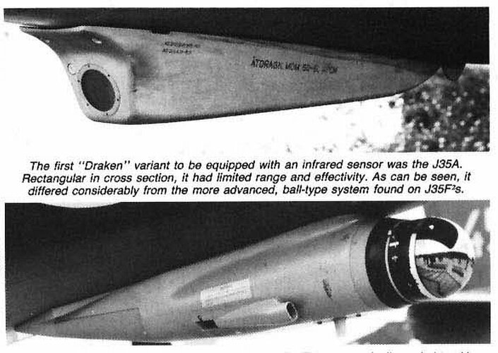
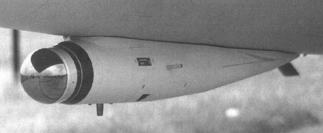
A Hughes IRST was also used on the Saab Draken. Two different models, an early limited one on J-35A with an improved one on the J35F2.

Designations mentioned for Draken IRST include Model S-71N, Model 71N, S-71RN.

DrakenIRST.jpg

Source: Aerofax Minigraph 12 Saab J-35 Draken (Robert F. Dorr, Rene Francillon, Jay Miller)

DrakenIRST2.jpg

Source: J-35 Draken (PKL)
 
Last edited:
Which also included a Hughes S-71N (AN/AAA-4) heat direction finder, capable of detecting IR-contrast targets only in the rear hemisphere (RBS) at a range that usually did not exceed 7-10 km. In real battles, pilots practically did not use the AAA-4 and considered it an extra load. The attitude towards it is clearly illustrated by the nickname - “Donkey dick”, probably given from the external similarity of both “devices”.
 
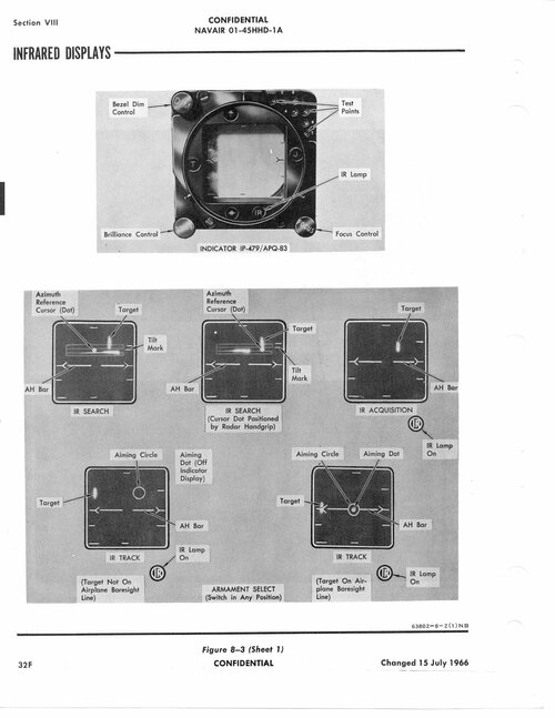
INFRARED DETECTING SYSTEM
Note
Refer to NATOPS Flight Manual for additional information.

DESCRIPTION

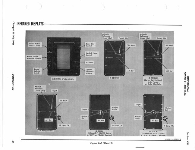
The infrared detecting set operates in three modes. These are IR search, IR acquisition, and III track. In these modes, IR data is displayed on the radarscope.

The IR. tone (200 to 2,000 cps depending on signal strength) is available in all modes, including radar modes.

While operating in either acquisition or track, an IR lamp will illuminate when the III detector elements receive sufficient IR energy. This will occur in either radar or IR mode. Steady illumination while operating in acquisition or track is an indication that the target is illuminating the elevation IR detector. If the IR lamp is illuminated and the IR tone is present when operating in radar track, it is possible (but not a requirement of the system) to change to IR track and maintain a lock-on. However, since range information is not available during IR operation, a lock-on cannot be maintained when changing from IR. track to radar track.

In IR search mode, the infrared detecting set receiver head is slaved to the radar antenna and searches a 4-bar scan pattern ahead of the aircraft. The search pat tern encompasses an area 38* to the left and 38° to the right of the aircraft boresight line in azimuth and a vertical arc of 7.9®. When left scan is selected, the IR receiver head sweeps a sector from 38° left 'to 10® right of the boresight line. In right scan, a sector 38° right to 10° left is swept. Center scan sweeps a sector 20*5 each side of centerline. The elevation plane of the search pattern may be .moved from. 45° above hori zontal to 30° below horizontal.

In the IR acquisition mode, the motion of the IR receiver head is still slaved to the radar set antenna and is controlled by the pilot’s radar control grip.
In the IR track mode, the scope display presents the position of the target relative to the aircraft 'bore sight line. The display consists of an aiming circle, aiming dot (/when the target is within 9® of the air craft boresight line), and a target signal strength line.

When the aiming dot is centered in the aiming circle, the target is dead ahead.

OPERATION

Scope displays showing the various modes of infrared operation are presented in figure 8—3, The power switch (27, figure 8—1) on the radar set control panel also controls power to the IR detecting set. When the switch is placed in st by , warmup power is supplied to the set and the nitrogen tank is pres surized to cool the detector cells to their operating temperature. When the power switch is placed in NOR with the mode switch in IR, search operation is ini tiated. For approximately 60 to 120 seconds a test target will appear on the lower right-hand side of the scope (approximately 20® below center) to allow a brief check of the IR search and. track capabilities. If another period of test target display time is desired, the power switch can be returned to STBY momen tarily and. then switched back to NOR.

In the search and acquisition modes of operation, movement of the antenna elevation, control knob (15, figure 8—1) on the radar control grip raises and lowers the search scan pattern. Side to side movement of the radar control grip (14, figure 8—1) moves the azimuth reference cursor laterally on the radarscope. The acquisition switch (19, figure 8-1) on the .radar con trol grip switches the set through the various modes of operation.

Movement of the IR receiver head along the 4-bar search pattern is indicated on the radarscope by a corresponding movement of a trace. When a target is encountered, the trace is intensified and deflected vertically to form a spike, and a "ping” (the IR. tone) is heard in the headset as the receiver head crosses the target.

When the acquisition switch is depressed, the search scan will stop and the IR receiver head is controllable in azimuth and elevation by use of the radar control grip and the elevation control knob. When it is desired to switch the set to the track mode, the acquisition switch must be released. Whether the target has or has not been acquired, the set will change from acquisition to track.

Once the acquisition switch is depressed, acquire the target and release the acquisition switch as rapidly as possible. The error signal system accumulates electrical energy during acquisition when the mechanical axis of the receiver head is not aligned 'with the target. This energy, which is fed. to the receiver azimuth and. eleva tion gimbal drive motors to keep the receiver head pointed at the target, can become excessive. When the
acquisition switch is released and the receiver head is not precisely aligned with the target, the drive motors may reposition the receiver head with a force sufficient to drive it through and off the target and break the lock-on.

The following are indications that tracking has not been initiated upon release of the acquisition switch:
• Vertical signal-strength line collapses to a dot. • IR tone frequency drops. • Steering circle drifts aimlessly. • IR lamp extinguishes.

Depress and release the acquisition switch if it is desired to return the set to the search mode. The search scan may be noisy for a short time after returning to search mode until the optical system stops rotating.

To be able to use the IR system with an AN/APQ-94 radar, the crystal oscillator BuOrd 2155846-1, -2, -3, or -4 must be installed in the electrical (missile) syn chronizer SN-253/APQ-83. Check for installation of the crystal oscillator (silver can through a glass win dow located in the top of the synchronizer in (aft end of the right-hand console).

TRACK AND SEARCH PROCEDURES

1. Search scan pattern — position • Adjust elevation of scan pattern to search de sired area. • When a target is encountered, position the scan pattern in elevation so that the target spike appears on the second or third bar. If the tilt mark is below the middle range mark, the IR system may detect ground targets.

2. Azimuth reference cursor — position • Move the azimuth reference cursor to the same azimuth position as the target.

3. Acquisition switch — DEPRESS • When the IR trace is sweeping the bar that pro vides the target spike, depress the acquisition switch. • The search scan will stop, and the IR receiver head will point in a direction corresponding to the position of the azimuth reference cursor.

4. Elevation — adjust • Adjust elevation until IR lamp is on steady, indicating that the target is being detected in elevation.

5. Azimuth — ADJUST • Sweep target in azimut huntil the spike exhibits maximum amplitude and brightness and the highest pitched IR tone is heard. 6. Acquisition switch — RELEASE • The acquisition switch must be released, to switch the set to the track mode. • Monitor the scope closely to ascertain that the desired target is being tracked. The steering in formation should move to the desired area, the IR lamp should remain on steady, and the IR tone should remain at a high pitch level. • As the target signal strength increases, the IR tone will increase in pitch. When it reaches the upper end of the frequency range, the target is in close proximity.

RANGE BURST FEATURE

The Range Burst feature* provides the AWG-4 Weapons System with radar range information for utilization during IR mode. When tracking an IR target, position the MODE switch on the Radar Control Panel briefly (3 to 5 seconds) to RADAR-NOR. position.
The radar will enter the Acquisition mode. Radar target range and azimuth information will be displayed on the radarscope. The radar target may be acquired if desired at this time by placing the acquisition bar be low the target, or it may be re-acquired in IR mode by returning the Radar Mode switch to IR.


F-8D Infrared.jpg
F-8D Infrared2.jpg
 
The design for the Hughes IRSTs are more or less as such.
Hughes After Howard also elaborates on this point. I can find the relevant pages if necessary.
Given the model numbers you're citing, it seems like AAA-4 might have been PbS. Worth noting that the later PbSe units had the Germanium coated(?) windows.
 

Attachments

  • US3445663.pdf
    1.6 MB · Views: 3
Hughes’s prominence in airborne search and track radars prompted us to try doing a similar combat job using infrared. The initial infrared search and track (IRST) systems did not form images, but could precisely track a target’s hot spot, such as the exhaust nozzle of a turbojet. Several designs begun in the late 1950s were installed in fighter aircraft: the F-101, F-102, and F-106, the F-8U, and the Swedish Viggen [sic]. The company produced more than 2,000 of these systems. The F-108, YF-12, and F-14 had more advanced versions.

Obviously he made a mistake with the Viggen instead of Draken.

The IRST telescope was initially pointed by the pilot or by the aircraft’s radar. Incoming energy was focused onto a ceramic wafer with an array of IR detector elements or cells. Our first designs used four detector cells arranged in a plus formation; the target object was a hot spot. Later, high performance systems used eight cells also set in a plus array: four horizontal and four vertical to the planned scanning view.

As the gimbaled telescope swept across a target, the captured thermal energy focused on the detector array passed across the vertical line of cells and the hot-spot target was detected. Gimbal scanning then stopped at that angle and the telescope spun in a small circle (technically referred to as nutated), so the horizontal cells could sense the IR spot. When the time interval between signals from the center two vertical and the center two horizontal detector elements was equal, the seeker pointed directly at the target. This timing balance was maintained to give angular information for the tracking process and for display in the cockpit. In the later F-14 IRST systems, all eight cells were in a vertical line and always scanned horizontally. Detector cell pulses from several separate targets were sent to a computer, which generated individual tracks while the scanning continued. Eight cells were enough to measure elevation angles without nutating the telescope; a higher speed small field scan was used for accurate single-target track.

Unfortunately, unlike a radar, these systems did not directly measure the distance to the target. In later years, significant refinements in pulse-Doppler radar performance minimized the need for a supplemental IRST system since background clutter was no longer a problem. Although the systems were still useful for counting the number of targets in a mass raid, the market that had been quite lucrative for Hughes disappeared.

Source: D. Kenneth Richardson - Hughes After Howard: The Hughes Aircraft Story
 
Interesting Hughes patent for a combined IRST / laser rangefinder from 1969. Reads similar to the Soviet KOLS/OLS-27 in principle.

 
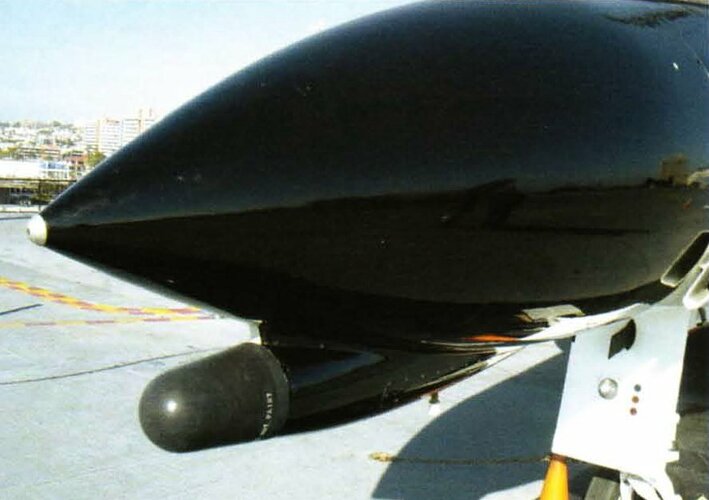
One item of equipment found on early production F-14s but soon deleted was the AN/ALR-23 infrared (IR) search and acquisition set. The IR seeker was located under the nose of the aircraft, and could be slewed independently of the radar antenna, or slaved to the antenna for co-ordinated tracking. The indium antimonide detectors were cooled by a self-contained Stirling-cycle cryogenic system, while the rest of the system was cooled by the same chilled oil used by the Phoenix missiles. The IR seeker proved ineffective and difficult to use, so it was deleted early in the production run.

Source: Dennis R. Jenkins, Grumman F-14 Tomcat (Aerofax)
 
Snoopy.jpg
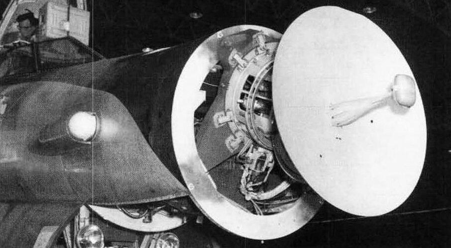
The AN/ASG-18 testbed "Snoopy" had IRST devices on either side of the nose.

Source: Jay Miller - Convair B-58 Hustler (Aerofax)

Snoopy-2.jpg
Closeup view. Source: Jay Miller - Lockheed Skunk Works (Aerofax)

The most recognizable feature of the two-phased Bold Journey program was the addition of a semi-hemispheric infrared tracker in place of the retractable probe and drogue refuelling boom located in the F-101B’s nose. Some 339 aircraft were affected before the program ended, including 153 aircraft that became F-101F’s following the update.
Source: Kevin Keaveney, McDonnell F-101B/F (Aerofax Minigraph 5)
 
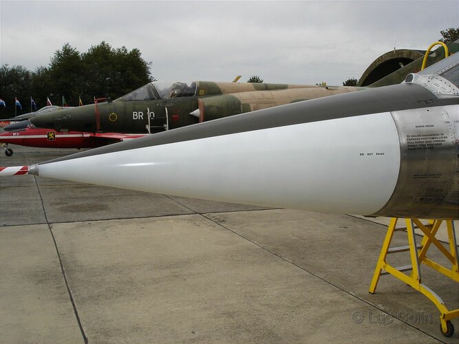
F-104 had an infrared detector in front of the windscreen, this looks to me similar to the system on the J35A Draken.

f-104g_fx-47_02_of_39.jpg

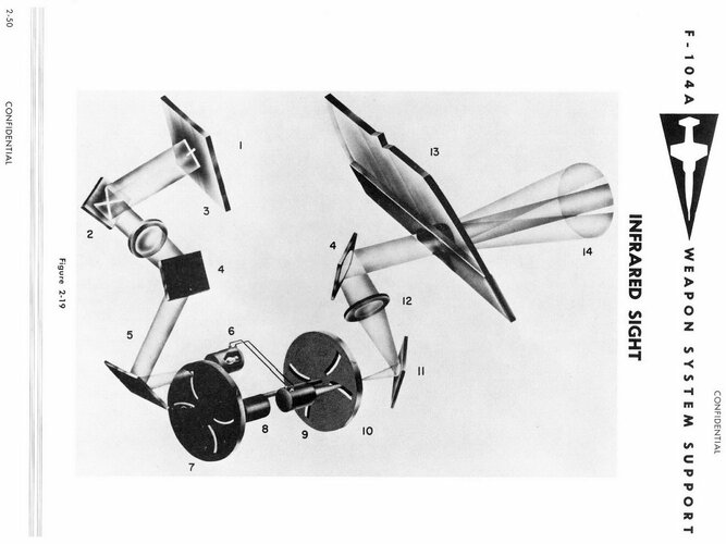
Infrared Sight

With the use of the infrared (IR) sight, attacks can be made in cases where the pilot is unable to see the target visually (Figure 2-19). The infrared radiation emitted by the target is scanned by a disc having two pairs of slits and a field of view of approximately 14°. The energy passing through a certain portion of the slits is detected by an infrared sensitive photocell and turned into electrical energy. The electrical energy is amplified and actuates a neon lamp. In front of this lamp rotates a disc similar to the scanning disc. Whenever the lamp is lit, an illuminated line will be projected onto the combining glass of the optical sight. Since there are two pairs of slits and the lines in each pair are effectively perpendicular, the lines will form a cross. The intersection of the cross represents the angular target position. The pilot flies the airplane to superimpose the sight reticle on the IR cross in the same manner as he would with a visual target.
F-104=IR.jpg

Source: Lockheed F-104A Weapon System Support (Lockheed LAC/513741)

According to this website, it was a Lockheed design:

A Lockheed development, the IR sight is integrated with the director gun-sight and shares its optics. Able to "see" targets by picking up emission of infra-red rays from heat sources, it can be used in the day and night

According to Martin Bowman, this did not perform at all well:

The F-104s also had an infrared (IR) sight however its pick up range was too short to be of any operational use. After the 1965 war, a serious effort was made by PAF engineers to improve its performance. These efforts did succeed in increasing the pickup range from less than half a mile to seven-eight miles against a single jet engine source by cooling the IR cell with liquid Nitrogen. The modified system did give the pilots good pick up ranges but because of ice formation, the system would clog and shut down. It required good 15 minutes for the ice to clear and the system to start functioning again. Unable to find a satisfactory solution to the problem, the effort was finally abandoned
Source: Martin Bowman Lockheed F-104 Starfighter: A History
 
Last edited:
So, according to Wikipedia the Phantom's AN/AAA-4 was designed by Texas Instruments. I am trying to check the referenced book to confirm.

According to these Congress Proceedings they were built by American Car & Foundry, New York, a manufacturer of railroad carriages.

https://www.google.co.nz/books/edition/Hearings_on_Military_Posture_and_H_R_401/4z42AQAAIAAJ

EQUIPMENT SUPPLIERS ( CFE)
American Car & Foundry, New York, AAA-4 infrared seeker.

A bit more detail from https://www.google.co.nz/books/edition/Department_of_Defense_Appropriations_for/87q2AAAAIAAJ

PROCUREMENT OF THE AN/AAA-4 INFRARED SYSTEM

Mr. SANDERS. You are procuring the AN/AAA-4 infrared system for the F-4H. This system is manufactured completely by Avion, a division of ACF. How are you procuring this system and why?

Admiral MASTERSON. This also is provided by the prime and subcontracted to American Car & Foundry as an original award following research and development. At the present time it is planned to terminate this procurement in the latter part of fiscal year 1965 buy, when we introduce the new pulse Doppler missile control system in this airplane.

This appears to contradict the opinion expressed in some books that the AAA-4 was not fitted to production Phantoms.
 
Last edited:
From An Outsider's View of the Phoenix, details of the F-14 IRST.

https://www.navair.navy.mil/foia/sites/g/files/jejdrs566/files/document/[filename]/FINAL VERSION Thesis_An Outisider's View of the Phoenix 2021-010204_0.pdf

ALR-23.png

INFRARED SENSOR

As a supplement to the radar, the infrared search and acquisition set passively gathers sufficient information to fire Phoenix or Sidewinder missiles if the radar is inoperable due to malfunction or to effective jamming by an enemy. The Phoenix missile would have to be launched in an active, rather than a semi-active, mode and depend on its own self-contained pulse Doppler radar, which is normally intended for terminal guidance only.

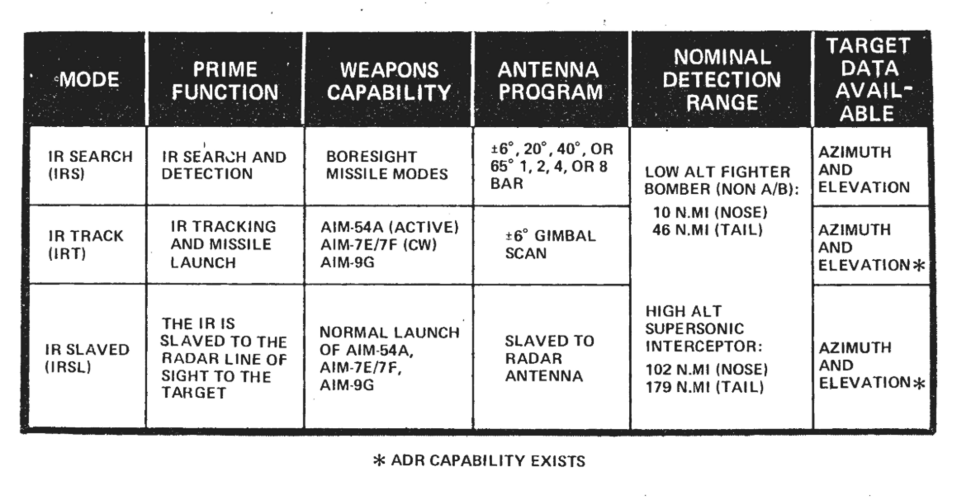
The field of view of the infrared telescope can be slaved independently of the radar antenna so that the sensor can augment the radar by searching an airspace volume in one direction while the radar scans another. The infrared sensor might search high altitudes, where the target-to-background radiation ratio is high, while the radar would scan low altitudes. The infrared field of view can also be driven by the AWG-9 radar antenna or it can drive the radar antenna, depending on the situation. The infrared sensor augments the radar because of its superior angular resolution capability; if the radar detects a group of targets together, the infrared sensor can distinguish each of the aircraft in the group. The infrared capabilities include three modes of operation:

1) Infrared search for infrared search and detection,
2) Infrared track for infrared tracking and missile . launch, and
3) Infrared slaved when the infrared is slaved to the radar line-of-sight to the target.

The nominal detection range for each of the modes for a low altitude fighter bcmber (without afterburner) is 10 nautical miles in a nose aspect and 46 nautical miles in a tail aspect. For a high altitude supersonic interceptor the nominal detection range is 102 nautical miles in a nose aspect and 179 nautical miles in a tail aspect. The infrared capabilities are summarized in Table IX.

The infrared sensor’s detectors are indium antimonide elements that can detect heat generated by exhaust in the 4-5 micron range. The detector array is cooled to operating temperature by the detector refrigerator, which is a self-contained, closed-cycle Stirling cycle refrigerator.
 
So, according to Wikipedia the Phantom's AN/AAA-4 was designed by Texas Instruments. I am trying to check the referenced book to confirm.
So - typical bullshit Wikipedia references.

The referenced book (The Great Book of Modern Warplanes) came in multiple editions. The one that is referenced in Wikipedia by ISBN, I have it, and it doesn't contain anything on the F-4 Phantom.

Now, these books are compiled from the Salamander Modern Fighting Aircraft large format books with minor updates. I own the F-4 Phantom book in this series, and lo and behold, the section on F-4 Avionics by Doug Richardson does indeed say "Texas Instruments AAA-4 ".

I guess there must be a version of "The Great Book of Modern Warplanes" which includes the F-4 material, but it ISN'T the one cited.
 
The mystery of the AAA-4 manufacturer... American Car & Foundry - solved?

By 1955, the railroads were concentrating on rebuilding existing cars. The passenger car builders such as AC&F were forced to close plants, concentrate on building freight cars, or diversify.

AC&F chose to continue moving into new areas, and, on 20 April 1953, purchased the Avion Instrument Company in Paramus, NJ.

Avion produced fire control and missile guidance systems for the military.

On 1 June 1954, American Car and Foundry changed its name to ACF Industries, Inc. Most of the iron foundries had been closed orsold, and the corporation was now as much involved in aerospace, electronics, and oil component manufacturing as railroad car construction.

On 1 June 1955, ACF Industries reorganized along product lines and created eight new divisions:

[..]

Avion Division - electronic devices and components. Plants at Alexandria, VA, and Paramus, NJ.

 
Avion Instrument Company did the engineering design of the original Sidewinder seekers from 1950 onwards

Unlike many of the others, the Avion Instrument Company was a very small operation in Paramus, New Jersey, with about twenty-five people, including nine engineers. Avion’s director, Richard F. Wehrlin, who had been chief engineer on the development of the Norden bombsight of World War II fame, had heard about McLean’s missile plans and knew that China Lake was looking for an outside contractor for the seeker. Don Friedman, a young electrical engineer, wrote Avion’s proposal, and China Lake in 1950 gave the company twenty-five thousand dollars (a large sum at the time) to complete a six-month development effort on the A head.

They were even considered to be given a production contract for seekers.

Until about 1954 Avion as well as Philco was thought to be a possible producer of the missile, and the navy even considered helping tiny Avion set up production facilities. The Sidewinder team was very impressed with the engineering work done by Avion and felt that the small company had made important contributions to the missile’s design. In the end, Avion decided it did not want to enter the manufacturing lists.

So, Avion getting a contract to make an IRST for the Navy makes a lot of sense.

Source: Ron Westrum, Sidewinder Creative Missile Development at China Lake (Naval Institute Press)
 

Similar threads

Back
Top Bottom