airrocket
Dreams To Reality
shockonlip yes email me...website is still valid although badly in need of an update. I sort of dropped out of the hobby stuff and went more commercial for awhile and website is more of a contact portal at this time.
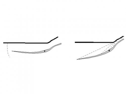
I became aware a renewed interest in 3D compression inward inlet stuff in the late 1990's. A comment from a failed NASA SBIR 2D inlet based concept proposal reviewer tipped me off. The reviewer stated that 2D inlet tech was not of interest at the time due to recent hyper 3D inward inlet developments. I'm always looking for a tip in reports, comments etc... (secret projects always been in my blood) and that set off whole series of unique discoveries and events for me. And ultimately lead me to contact Paul C. which set off another series of discoveries....
I use a combo of hobby HP, commercial and home brew motors. HP is good for up to around M2 after that the cost an motor size becomes a limiting factor and you need go commercial based with "FUNDING" unless you have very deep pockets. Many of the small business companies that serve the HP hobby market also do commercial, military stuff and often have hardware and propellant grains left over from those projects at reduced cost. Also much of micro turbine hobby motors can be combined with automotive based turbocharger components to yield ATR hardware. I'm an integrator more than an inventor I like to fly hardware not much of a lab rat.
")