Hawker Supersonic V/STOL - HS.1205 to P.1216

damian2

ACCESS: Restricted
Joined
8 October 2009
Messages
36
Reaction score
14
Hi all!

I'm looking for largish line drawings for Hawker's HS.1205-11 and P.1216 which I can use in creating blanks of those two machines :)

I've gone through the forums with the search button but haven't found anything of sufficient size nor clarity to base my drawings off of!

Any help would be greatly appreciated!

D
 
Regarding the P.1216, there should be a book about it coming out this year. There's also a 3 view of it in the British Secret Projects: Jet Fighters Since 1950 bit it's kind of small. Of course, if anyone has a nice larger three view of it, I'll be more than happy to download it as well. ;)

Also, there were different versions of it, but I'm guessing you're looking for the version with the chin inlet as shown in the BSP book.
 
These are the two I'm looking for. As for the book great idea but I'm a flight student so free sources are a must here, or if someone is willing to scan and email me the pic that would be great. I just need bigger, clearer versions of the 3 veiws below for the vector drawing phase of the profile :)

But thanks for looking!
 
free sources are a must here, or if someone is willing to scan and email me the pic that would be great.

::)

Mike's book will be absolutely essential to anyone wanting to draw or model these aircraft. I suggest you start saving.
 
damian2 said:
These are the two I'm looking for. As for the book great idea but I'm a flight student so free sources are a must here, or if someone is willing to scan and email me the pic that would be great. I just need bigger, clearer versions of the 3 veiws below for the vector drawing phase of the profile :)

But thanks for looking!

When it comes to vector drawing those images should be fine. Do the line art first, since vector graphics are scalable, it shouldn't be a problem. Then just scale them up and perform your coloring there, or move them into your preferred choice of software for adding the color. ;)
 
I've found again my very basic raw-drawings (cdr-files) of the 1205 and
the 1216, from about 10 years ago. But be warned, it's as said before:
VERY basic ! If you think, they're useful for you, drop a PM with your
mail adress.
 

Attachments

  • 1205.JPG
    1205.JPG
    26.9 KB · Views: 1,403
  • 1216.JPG
    1216.JPG
    26.3 KB · Views: 1,389
Sundog said:
When it comes to vector drawing those images should be fine. Do the line art first, since vector graphics are scalable, it shouldn't be a problem. Then just scale them up and perform your coloring there, or move them into your preferred choice of software for adding the color. ;)

That much I do get believe it or not ;) What concerned me was the poor quality which would lead to a difficulty iin getting the details right.
 
damian2 said:
Sundog said:
When it comes to vector drawing those images should be fine. Do the line art first, since vector graphics are scalable, it shouldn't be a problem. Then just scale them up and perform your coloring there, or move them into your preferred choice of software for adding the color. ;)

That much I do get believe it or not ;) What concerned me was the poor quality which would lead to a difficulty iin getting the details right.

You're looking for drawings with panels lines and such. Yeah, I overlooked that.
 
Sundog said:
damian2 said:
Sundog said:
When it comes to vector drawing those images should be fine. Do the line art first, since vector graphics are scalable, it shouldn't be a problem. Then just scale them up and perform your coloring there, or move them into your preferred choice of software for adding the color. ;)

That much I do get believe it or not ;) What concerned me was the poor quality which would lead to a difficulty iin getting the details right.

You're looking for drawings with panels lines and such. Yeah, I overlooked that.

Hehehe yeah. I shall be triumphant though!! Mark my words!!
 
I've built 3D CGI models for both for the x-plane flight sim http://x-plane.org/hawkers/Hawker_Harriers.html. Beware of the 3 views that are around (e.g BSP books)! especially for the P1216!!
 
danielgrimes said:
I've built 3D CGI models for both for the x-plane flight sim http://x-plane.org/hawkers/Hawker_Harriers.html. Beware of the 3 views that are around (e.g BSP books)! especially for the P1216!!

I'm going through your list and adding models to my to line art/profile list!!! Wow!!! What are the chances of getting port side profiles to render off of? Of course all contributions will be acknowledged!!!

D
 
It's relatively straightforward to get profiles. Download x-plane from x-plane.com and you get a free demo. Download the aircraft from the link above and open them in the 'planemaker' application that comes with x-plane. You can then rotate etc to get the profiles you want.

Re your profile list, the one exemplary Harrier i have not yet built is the P1184-16. This was an early 80s design (just about 2nd get Harrier) tha in addition to the pilot, had a tail gunner!!
 

Attachments

  • Harriers2.jpg
    Harriers2.jpg
    65.1 KB · Views: 1,258
Found these two models on Ebay from the usual Philippines firms. They are somewhat crude, but
for any non-modelmaker fans of the 1216
Uk 75
 

Attachments

  • 6742_35.jpg
    6742_35.jpg
    7.8 KB · Views: 1,348
  • ca40_2.jpg
    ca40_2.jpg
    3.4 KB · Views: 1,294
Had a look on ebay. They look OK from the pics shown, but an underside view could be interesting, as that is missing from most published GAs.

Might be tempted if they weren't so FLIPPING EXPENSIVE! £100 plus!
 
danielgrimes said:
Re your profile list, the one exemplary Harrier i have not yet built is the P1184-16. This was an early 80s design (just about 2nd get Harrier) tha in addition to the pilot, had a tail gunner!!

I interviewed the chap who designed that. He chuckled. When you consider where the hot exhausts go, and how much vibration occurs at the tail of a Harrier, you can see why. It's from the early 1970s, not 80s.
 
danielgrimes said:
Re your profile list, the one exemplary Harrier i have not yet built is the P1184-16. This was an early 80s design (just about 2nd get Harrier) tha in addition to the pilot, had a tail gunner!!

I see the tail gunner, but where's the tail gun? ;D

Also, does anyone know what that thing on the underside of the fuselage between engine intake and the first pair of engine nozzles is?
 
harrier said:
I interviewed the chap who designed that. He chuckled. When you consider where the hot exhausts go, and how much vibration occurs at the tail of a Harrier, you can see why. It's from the early 1970s, not 80s.

What say we change the tail gun to a remote-controlled mount and adopt a bigger canopy set like either the Harrier trainer or naval P.1154, but with the backseater facing backward so he can intuitively aim the tail gun (and suffer from none of the vibrations)? ;D

(In a way like the Il-102.)
 
dy031101 said:
Also, does anyone know what that thing on the underside of the fuselage between engine intake and the first pair of engine nozzles is?

It looks like an intake hardpoint, to me. Like what you see on the F-16 for carrying the targeting pods.
 
The 'gunner' was for aiming the Taildog missiles. Don't know what the ventral thingy is. This was a 'Wet Tuesday Afternoon Wonder' effort anyway, so it could have been anything - sensor turret, hardpoint etc.
 
Hi out there.
While I was reading Michael Pryce's new book BAe P.1216 I saw a mention of the P.1216-52 whichwas a P.1216-50 with side intakes. Does anyone out there have a 3 view of this? It would be interesting to compare with the P.1216-50
 
In all my research I did not see a picture of this - it is mentioned in the P.1216-50 brochure, but the draft copy at Brooklands has the picture missing!


However, from the description it seems the intakes/front fuselage were the same as the P.1230-6 shown in my book.
 
IIRC the model at Newark Air Museum is thus configured. There are pics on here of that.

If this is for a D/F project, you may be better of with the chin intake version - straighter, less losses...
 
The intakes on the Newark model were different from the -52 description. The former were 'bodged on' to a model originally with a regular single inlet in order to see the RCS benefits of twin intakes. The 'bodging' shows in the cockpit/LERX.
 
Thanks for that. Rather explains why I was underwhelmed by dome aspects of the craftsmanship of same.
 
Here are some graphical photos of P.1216 in RAF camouflage, i am not sure will these help you or not/ and also i have no idea about the Nose of the P.1216 on the 2nd last picture .

Regards,
~AK
 

Attachments

  • P1216C_UKRN90.jpg
    P1216C_UKRN90.jpg
    25.1 KB · Views: 359
  • P1216E_UKRAF91.jpg
    P1216E_UKRAF91.jpg
    27.3 KB · Views: 333
  • P1216A_UKRAF91.jpg
    P1216A_UKRAF91.jpg
    26.7 KB · Views: 292
  • P1216A_UKRAF90_2.jpg
    P1216A_UKRAF90_2.jpg
    26.4 KB · Views: 682
  • P1216A_UKRAF90.jpg
    P1216A_UKRAF90.jpg
    23.9 KB · Views: 694
  • P1216A_UKRAF87_3.jpg
    P1216A_UKRAF87_3.jpg
    25.4 KB · Views: 698
  • P1216A_UKRAF87_2.jpg
    P1216A_UKRAF87_2.jpg
    25 KB · Views: 742
  • P1216A_UKRAF87.jpg
    P1216A_UKRAF87.jpg
    24.6 KB · Views: 809
Re: Hawker HS.1205-11,P.1216 & P.1214

I have this drawing from Internet,the BAe P.1214.
 

Attachments

  • 14199549223_0e547d727d_o.jpg
    14199549223_0e547d727d_o.jpg
    317.4 KB · Views: 539
The forward swept wing is P.1214, rather than P.1216.
 

"The first of the more radical modifications of the original Harrier was the study of the STOVL supersonic fighter HS.1205. This was to be powered by an improved Pegasus II engine with afterburner in the front nozzles and with LERX technology (Leading-Edge Root Extensions) while the air inlet was located under the cockpit. It was also used wing developed by McDonnell Douglas originally for the Harrier II (AV-8B) with the intention to significantly increase maneuverability. Work on the project lasted from 1976 to 1979."
 
Last edited:
After the Harrier was commissioned and its successive versions developed, Hawker, Hawker Siddeley and finally BAe continued to work on numerous VTOL fighter projects.
The staffs regularly demanded a supersonic successor to the Harrier and Hawker, with its experience on the P.1150 and P.1154, was naturally in the best position to finally release a supersonic VTOL. Almost all of these projects used the vector-pushed turbojet formula associated with the PCB technique to provide the power needed for a supersonic VTOL.

Hawker logically resumed developments from P.1154 by beginning the Studies on HS.1185. It should be noted that none of these projects led to an operational device or even a prototype and that to date no supersonic VTOL has yet been put into service despite the appearance in the early 1990s of the Yak-41 M (the first devr Lockheed F-35B if this program is completed for the vertical take-off version).

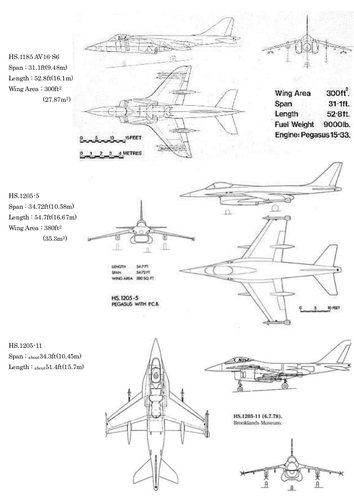
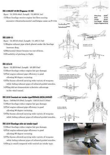
The Hawker Siddeley HS.1185 was a VTOL supersonic fighter project, also known as AV-16-S6, which began its studies in 1974. The aircraft was drifting from the AV-16, a subsonic successor to the Harrier studied in cooperation with McDonnell Douglas in 1973 and abandoned in 1976. The AV-16-S6 was to be powered by a Pegasus 15-13 equipped with PCB pipes, to be armed with two 20 mm guns and four IR Sidewinder missiles under wing pylons. The aircraft had a wingspan of 9.4 metres and a length of 16.2 metres and was essentially an improved version of the P.1154 for the US Navy and the Royal Navy.
The Hawker Siddeley 
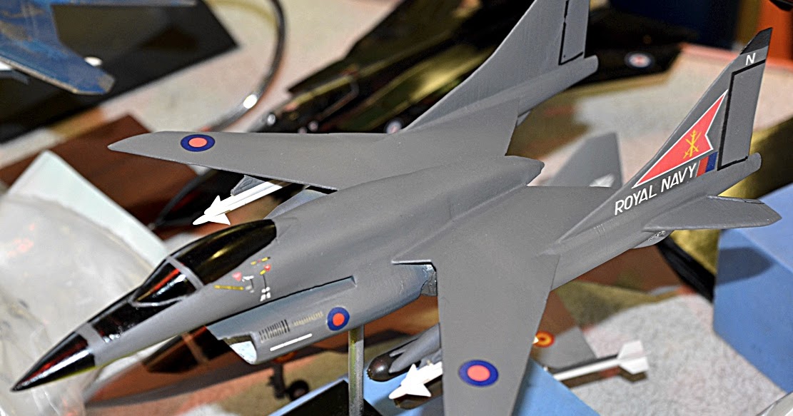
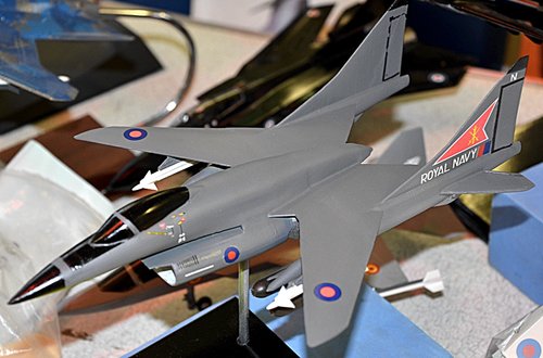
HS.1205 was also a VTOL supersonic fighter project powered by a Pegasus II with four steerable pipes equipped with "Plenum Chamber Burning" type, LERX (Leading-Edge Root Extensions) and an entrance air under the nose.
The LERX wing extensions were designed by McDonnell Douglas for the Harrier II and create vortexes on the wings to increase the aircraft's manoeuvrability.

Studies on HS.1205 began in the summer of 1976 and lasted until 1979. The HS.1205 was an aircraft designed to be highly manoeuvrable in air combat and the development team believed that the directed thrust was the best configuration for this class of aircraft, a philosophy shared by the RAF.

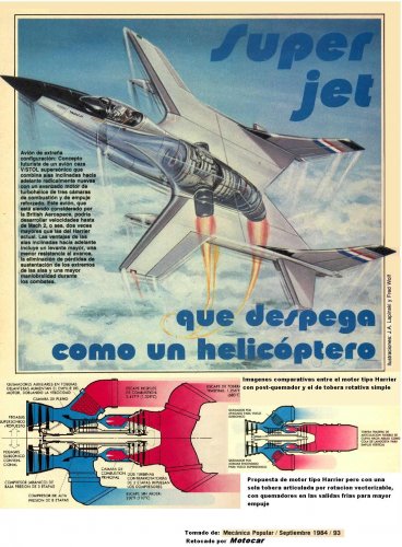
With the PCB system, the fuel no longer burns in the post-combustion channel but in an enclosure (Plenum Chamber), the thrust is more important and the thermodynamic efficiency very favorable. Bench tests conducted by Rolls-Royce showed an increase in the cold flow thrust of almost 100%, with the total thrust of the reactor increased by about 50%.
In the case of Pegasus, which provides 9980 kgp, the thrust in the front pipes increases from 5000 to 7500 kgp. PCB behavior and ignition tests were conducted at simulated supersonic altitudes and velocitywithout major difficulties. With the PCB on, the specific fuel consumption rises to about 2.5 times that of a normal Pegasus, but in flight only two-thirds of that of a conventional post-combustion device.

The development of pcB pipes continued throughout the 1970s and in 1984 a complete Harrier fuselage (built in Kingston from elements of the Harrier GR Mk.1 XV798 and T Mk.2 XW264 damaged in landing accidents) and equipped with PCB pipes was tested on a test bench at Shoeburyness.

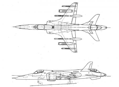
The oldest HS.1205 configurations were synthesized with the 
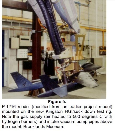
HS.1205-5, which had four Sidewinder infrared missiles mounted under the wings. The engine was placed under the fuselage to retain maximum space for the structural fuel tanks and PCB devices were installed on the front steerable pipes. Tests were carried out in the wind tunnel to determine the best way to prevent the re-ingestion of hot gases through air intake.
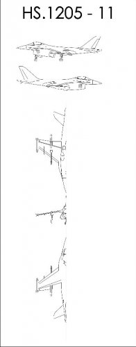
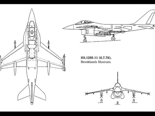
The HS.1205-11 had a configuration similar to that of the HS.1205 with a single cannon mounted in the right root of the wing. The later HS.1205-15 used more traditional lateral air intakes as on the Harrier.
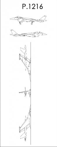
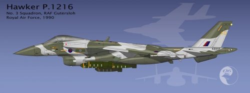
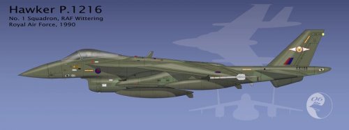
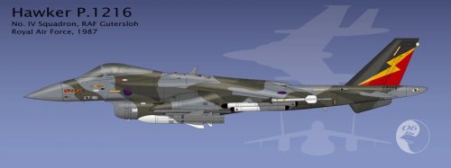
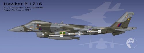
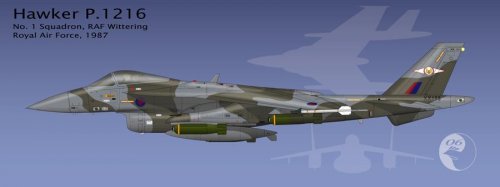
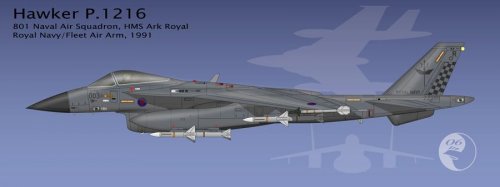
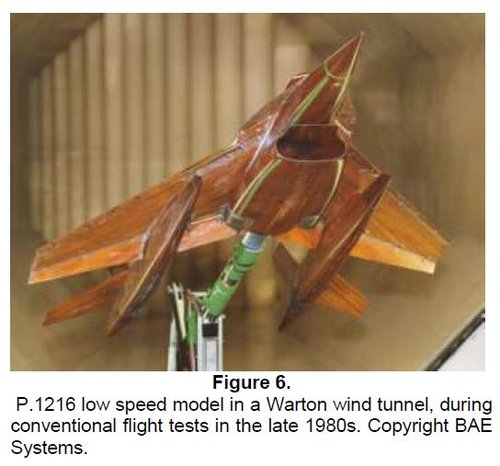
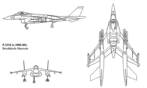
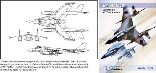
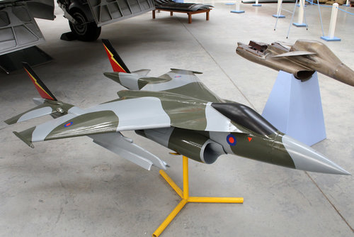
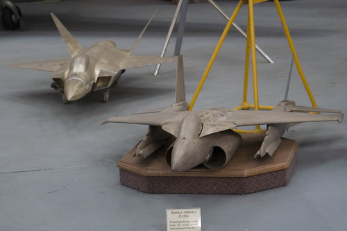
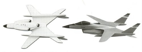
The configuration of the HS.1205 posed technical problems that were difficult to solve. If the four pipes were placed high enough on the fuselage, the tails would receive the hot flow of the reactor causing excessive vibration and damage. If the four pipes were placed under the fuselage the drag increased and the horizontal thrust became too out of focus. There was also the possibility of pitching in conventional flight. These factors led to the abandonment of the HS.1205 concept, essentially a derivative of P.1154, and to the study of the P.1212/P.1214/P.1216 series.
 
Last edited:

Attachments

  • 1216 low speed model.JPG
    1216 low speed model.JPG
    46.4 KB · Views: 387
  • FULL_TEXT.pdf
    548.3 KB · Views: 41
  • 318beb5ae1dbf4ec27bec0a4b213234f.jpg
    318beb5ae1dbf4ec27bec0a4b213234f.jpg
    36.9 KB · Views: 333
  • 1216 test.JPG
    1216 test.JPG
    75.4 KB · Views: 323
  • main-qimg-4e0c14d6b37d3c0ccd98a2b09d0cfdc1.jpg
    main-qimg-4e0c14d6b37d3c0ccd98a2b09d0cfdc1.jpg
    115.2 KB · Views: 336
Last edited:

Attachments

  • 20728097953_e712184f7a_b.jpg
    20728097953_e712184f7a_b.jpg
    121.1 KB · Views: 312
  • 47592633012_4fb240b03b_b.jpg
    47592633012_4fb240b03b_b.jpg
    147.3 KB · Views: 272
  • 21162309099_55301a0567_b.jpg
    21162309099_55301a0567_b.jpg
    138.3 KB · Views: 281
  • 10271278346_c02526acfc_b.jpg
    10271278346_c02526acfc_b.jpg
    151.6 KB · Views: 282
  • 2735843617_3cb17df2ba_b.jpg
    2735843617_3cb17df2ba_b.jpg
    108.3 KB · Views: 311
Last edited:
Hi! 1214.
Hard to imagine how three exhaust nozzles work. Some hint in the last drawing?
 

Attachments

  • 1214 MODEL.JPG
    1214 MODEL.JPG
    285.8 KB · Views: 298
  • 1214.JPG
    1214.JPG
    50.9 KB · Views: 314
  • RR VSTOL ENGINE.JPG
    RR VSTOL ENGINE.JPG
    143.4 KB · Views: 352
Last edited:
Internet information including my tiny opinion at the bottom.
 

Attachments

  • HS f.jpg
    HS f.jpg
    288.1 KB · Views: 335
Last edited:
Mmmmm............Thanks a lot. F-35B's tail nozzle mechanism is Yakovlev's patent. Lockheed bought it from Yakovlev.
Perhaps F-35B's afterburner it's self is vectored nozzle.
I feel P.1214/1216's tail pipe is too short to have such a Yakovlev mechanism.
I imagine that P.1214/1216's tail pipe vectored downward 90 degree using round shape two deflectors which rotate 90 degree and 45 degree.
 

Attachments

  • tail nozzle.JPG
    tail nozzle.JPG
    47.1 KB · Views: 327
Last edited:

Similar threads

Back
Top Bottom