I expect the parts can all be changed to play with
different conditions.
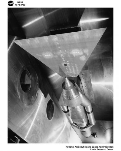
Looks like a very flexible fixture.
On some of the pictured configs:
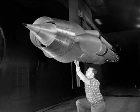
Note translating inlet spike.
Note shape of inlet spike.
Spike is probably changeable.
Looks like 2 external cone shocks used on the one pictured.
Note external cowl angle versus spike angle. Spike
angle will close in on cowl angle if internal angles
match external appearance. Flow will be restricted
so internal shocks will form.
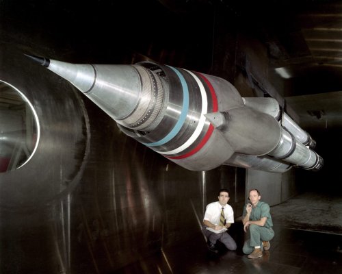
Center tube can probably hold a turbine cycle, or not.
In fact the center tube looks changeable as different
center tubes seem to be installed in several pix.
Looks like cowl can be changed as well. Note the cowl
appears longer (fore-aft) in some pictures. Hard to
tell for sure. I would expect something like this though
to play with that parameter and shock on lip for different
spikes, etc. Plus they could play with different
flow separation control devices too.
Note what looks like different spike bleeds
(before throat, at throat, past throat (subsonic diffuser)
on the spike itself. Certainly programmable. Probably
dumps to one of the side tubes.
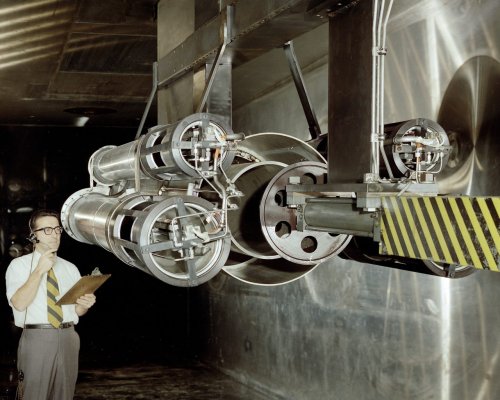
Note side tubes, they seem to tap into flow at different
places and hard to tell, but seem to rejoin flow downstream.
Some side tubes don't have extensions but some seem to have
extensions that look a little like nozzles (maybe).
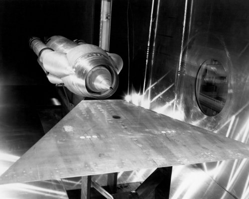
Look at the largest side tubes and where they are when the
spike is fully retracted. Looks like they are over the
throat and maybe even have upstream and downstream ways
to tap into that flow (would have to see inside to confirm).
for playing with bleeding the flow near the throat.
Smaller side tubes seem to be attached to subsonic diffuser
downstream of throat or even near compressor face if a such
a cycle is installed in the center case. Could also dump
spike bleed.
Cool test fixture !
Of course would need to motorize some of it.
Every supersonic inlet freak should have one!
It's like an SR nacelle only a lot easier to test with.

") I wonder if, given the time frame and those extra pictures, it might even be possible to identify the program they're associated with. (No, that's not a request.
I wonder if, given the time frame and those extra pictures, it might even be possible to identify the program they're associated with. (No, that's not a request.