Rolls-Royce Crecy engine which was to be installed in Spitfire

Andrewjs2007

ACCESS: Restricted
Joined
24 June 2007
Messages
42
Reaction score
5
Dear All

Does anyone know if therew are any photos/plans/sketches of this project? -

"Supermarine Spitfire Mk II, P7674 had been delivered to Hucknall and was fitted with a Crecy [Rolls-Royce prototype engine] mock-up to enable cowling drawings and system details to be designed."

taken from wikipedia


Thanks


Andrew
 
Rolls-Royce Heritage Trust has published a booklet, #21 in their Historical Series, which will tell you more than you probably want to know about the CRECY.
 
The wikipedia page seems pretty good; given what is published elsewhere, I'd imagine most of the information comes from the RRHT booklet listed in the footnotes. I've never heard anything personally about a mockup engine fit. I re-read another article on the Crecy I had but there's no mention of any installations there either.
 
They were also to put a pair on a de Havilland Mosquito and the government said no.If you do they would kill the Mosquito.
 
Hello everybody,

The following site has a diagram of a Crecy front section, within what looks to be Spitfire (or at least, Merlin) firewall and spinner plate cross-sections. It looks like the interior exhaust ports were to be fed out in a row above the exterior pipes:

http://www.flickr.com/photos/97039613@N00/4926517458/sizes/l/in/photostream/

No side or top views, I am afraid! There are some other Crecy diagrams, also two pictures of a cowled Pennine engine that I have never seen before:

http://www.flickr.com/photos/97039613@N00/page4/

Cheers,

Mike
 
There is also a good article on the Crécy in the January '11 edition of Aeroplane. Among other things it has a photo of a Hawker Henley (L3385, tail no. K5115) which was delivered to Hucknall in March of 1943 for use as an actual engine testbed for the program, but ultimately the conversion never happened.
 
Mike... hatsudoki
Glad you liked the pictures on Flickr.. part of the collection I have on RR engines. The Pennine drawings are from the preliminary specs for the engine dated Sept 1943.
 
Hello tartle,

Thank you for posting them. I am always looking for more information on aeroengines, especially the later piston engines.

Cheers,

Mike
 
As I have said elsewhere I have just acquired the RRHT HS21 book on the Crecy.

I am posting a drawing of a 1943 post-war PI project based on Crecy technology but using Eagle II/Sabre configuration to give an H24...fascinating!

Other interesting diagrams show ideas for adapting the Mustang FTB for use as the test bed for the Crecy and a cutaway of the Crecy MK. II by Lyndon Jones, a technical illustrator at RR Derby in the 1950's (the famous Dnl series of illustrations, many of which I have used in the early gas turbine thread were from the technical illustration department set up by Dunwell in WW2 -he was a fourteen year old tea boy in the experimental department and when a Jumo was stripped and laid out all the chiefs arrived to look, handle and discuss... just as they went off for lunch Hives remarked they needed to capture the information on the components for discussion. While they were at lunch Dunwell, who was keen on drawing and art. did some 3-D sketches and cutaway sections and left them on the bench next to the components. Hives saw them and was enthusiastic, asked who had done them. Dunwell stepped forward expecting to be told off for time wasting... Hives congratulated him on his initiative and announced he had a new job...the Technical Illustration Department was now born!), did many engine drawings using parts detail drawings and photos in any combination; RRHT published a book of many of them.
 

Attachments

  • Proposed 24cyl P! 2-stroke civilian engine.jpg
    Proposed 24cyl P! 2-stroke civilian engine.jpg
    1.1 MB · Views: 864
  • RR Crecy installation alternatives-Mustang FTB.jpg
    RR Crecy installation alternatives-Mustang FTB.jpg
    396.9 KB · Views: 852
  • RR- Crecy Mk II.jpg
    RR- Crecy Mk II.jpg
    1,000.9 KB · Views: 839
The intriguing thing about the Mustang FTB with Crecy is how it extends pre-war work on generating thrust from radiators and exhausts that de Paravicini and Ellor worked on in the mid-30s and patented the results. See UK patent GB472,555. Aero - engine accessories. ELLOR, J. E., and PARAVICINI, T. P. DE. April 8, 1936, No. 10373. [Class 4] A liquid cooling radiator of an aero-engine is accommodated in a divergent-convergent duct with forwardly directed intake and is carried by the fuselage in a position aft of the aircraft ... ...see fig 1 below and original patent.
 

Attachments

  • RR ellor and paravicini-espacenetImage-GB 472555.jpg
    RR ellor and paravicini-espacenetImage-GB 472555.jpg
    4.5 KB · Views: 703
Tartle,

That H24 engine wouldn't happen to be related to the Falcon flying boat engine by any chance? (Before you all jump down my throat, not the WW1 Falcon, the Post WW2 one)

Chris
 
Eagle came before the Falcon in WW1 so why not name the second H config after the Eagle II.. the Falcon II... to be honest I don't know the answer but now I know the question I'll look into it!
In researching the supercharging of aero engines I was intrigued to see that Szydlowski-Planiol of Turbomeca researched such devices from 1938 and the military insisted that comparisons of the Hispano-Suiza 12Ygrs, for the Dewoitine D520 aircraft be made, We know from Rod Banks's 'I kept No Diary' that H-S designed poor superchargers and he was trying to get RR to help them. In the event the French Government were going to put the Merlin into the D520 and had all but negotiated a manufacturing licence for Ford of France when the Germans attacked and made the deal irrelevant. In the meantime the comparisons showed that:
The Turbomeca supercharger gave an extra 3,000 feet on full throttle height but also gave an extra 100 hp at take-off for the same inlet pressure.. result was that this supercharger became standard for the D520 and the 12Y-45 engine as it was called went into production.
Why is this relevant to Crecy?
Before the war Spike Corbitt, chief engineer for the Crecy after Dick Thomas,had visited Josef Szydlowski (JS) in France and seen the supercharger and had been impressed with the design, which improved the efficiency of the 12Y-45 by as much as 15% under certain operating conditions. As the Crecy was PI and did not have a carburetor it was worth thinking about doing a 'Szyd' to pick up the benefits too.
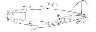
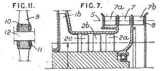
What JS had done was to fit variable intake guide vanes fed by a plenum chamber to swirl air into the eye of the impeller and so reduce the losses. JS's patent GB503652 (see sketch below) shows the setup.
abstract reads:
"Centrifugal blowers. SZYDLOWSKI, J., and PLANIOL, A. P. E. March 10, 1938, No. 7474. Convention date, March 10, 1937. [Class 110 (i)] A centrifugal blower with adjustable inlet guide vanes has a single inlet and the rotor carries on the suction side of the impeller blades 1b, Fig. 7, a set of blades 2a .. 2c to impart considerable deviation to the inlet fluid without shock or separation. The inlet vanes 7 are mounted on a pivot axis 5 and may be controlled by hand or automatically; additional vanes 7a, 7b may be carried by a movable frame 8, vanes 7a imparting a negative component of rotation to the fluid, vanes. 7b a positive component, and vanes 7 no component. The blades 2a . 2c are spaced so that the fluid stream from any blade in one set passes between two blades of the following set and.their edges may be connected by a rim. Each set of blades may consist of blades 9, Fig. 11, 'of light metal with prismatic bases 10 clamped around the shaft 12 by steel hoops 11 preferably shrunk on. When the blower is used as a supercharger, the inlet vanes 7 may replace the butterfly valve of the carburetter. Outlet guide vanes may be used, as described in Specification 484,373."
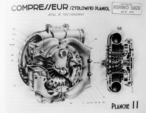
Gerry Wells, a member of AEHS, has researched the S-P supercharger and his members-only essay includes a cutaway (second attachment). The vanes we are interested in are labelled V.
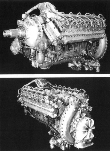
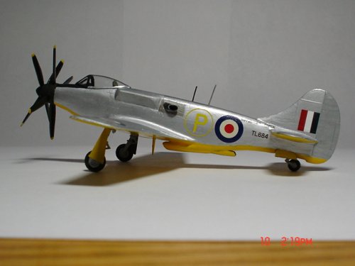
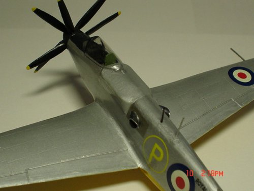
As I have been used to looking at Merlin pictures with the carburetter before the s'charger intake it had not registered that the two spindles I could see at the inlet to the supercharger on the Crecy were different. They are the axes of rotation of two butterfly throttle valves that aso act to swirl the inlet air in a 'vortex' that improves the matching of the swirling airflows into the impeller eye. You can see the spindles on the lower photo of the Crecy. The ability to improve matching at lower altitudes by using vortex throttling improves the performance compared to non-swirl intake.
 

Attachments

  • RollsRoyceCrecy2.jpg
    RollsRoyceCrecy2.jpg
    83.4 KB · Views: 286
  • S-Pphoto-cutaway of supercharger.JPG
    S-Pphoto-cutaway of supercharger.JPG
    519.4 KB · Views: 232
  • szydlowski- vortex into supercharger-GB503652-espacenetImage.jpg
    szydlowski- vortex into supercharger-GB503652-espacenetImage.jpg
    10 KB · Views: 637
Whilst digging in an even bigger tea chest called Kew I noticed in a search a document "Estimated Performance of a Supermarine Spitfire (with Rolls-Royce P. I. Engine)".
Dated March 1942, most of it is a technical discussion on calculating IHP but it does refer to the challenge of getting the air consumption to a minimum throughout the flight cycle as the 2-stroke ports, configured for take-off, are too big at cruise so give losses due to more rev/min than necessary if ports were variable.
The report summary reads:
"The net power available from the Rolls-Royce two-stroke engine has been estimated using the analysis of test data made by Mr R.W. Fenning. The speeds it would give the Spitfire have been calculated with and without exhaust thrust. The results are as follows:-
Case I. Engine with a single stage gear driven supercharger
Maximum B.H.P. (static) 1630 at 14,200 feet.
Level speeds at 20,000 feet with and without
exhaust thrust allowance: 451 mph and 403 mph.
Case II. Engine with a two-stage gear driven supercharger
Maximum B.H.P. (static) 1270 at 27,100 feet.
Level speeds at 35,000 feet with and without
exhaust thrust allowance: 486 mph and 420 mph.
Compared with a Griffon engine having the same supercharger compression ratio as in case I the two-stroke engine has a lower maximum power height by about 3,000 feet; but due to the advantageous exhaust thrust the Spitfire fitted with the two-stroke engine reaches 451 mph at 20,000 feet as compared with 413 mph at 23,000 feet with the Griffon.
Preliminary consideration is given to the cruising condition of the engine and the control of the exhaust back pressure."
Now will take a period of study to digest the next couple of dozen pages!... but it seems we are in an apples and pears situation if we are not careful in our 'what-ifs'.
 

Attachments

  • crecy spitfire-avia6-5508-008.jpg
    crecy spitfire-avia6-5508-008.jpg
    160.6 KB · Views: 212
Good stuff T,
& interesting that duct flow efficiencies which were crucial to turbines were being encountered by Crecy..

& AFAIR, that variable vane throttle/supercharger intake tech ended up being investigated by NACA,
via Jumo 213, & Junkers engineers admitted they'd adapted it from captured Mikulin mills - Soviets had likely
got it from the French, in a case of - what goes around , comes around..
 
From RR Heritage book
 

Attachments

  • b7e38a44ad3459829abf3f7a01f431adcaef84db.jpg
    b7e38a44ad3459829abf3f7a01f431adcaef84db.jpg
    209.5 KB · Views: 162
  • 40670e2dd42a28343b7feee356b5c9ea14cebf3f.jpg
    40670e2dd42a28343b7feee356b5c9ea14cebf3f.jpg
    2.2 MB · Views: 136
  • 523027f3d7ca7bcbf6411dc7b3096b63f724a8db.jpg
    523027f3d7ca7bcbf6411dc7b3096b63f724a8db.jpg
    4.1 MB · Views: 136
  • dbd38064034f78f045d5421b74310a55b2191c3e.jpg
    dbd38064034f78f045d5421b74310a55b2191c3e.jpg
    1.4 MB · Views: 146
  • c72fbbef76c6a7ef1570c7aaf0faaf51f2de66a2.jpg
    c72fbbef76c6a7ef1570c7aaf0faaf51f2de66a2.jpg
    654.2 KB · Views: 211
Hell of an idea ! With an up-to-date P-51 fuselage look alike (carbon fiber, the usual business) it would make a terrific racer. Rare Bear ? meh. Go back into the alaskan cave.
 
Using the RRHT books on the Crecy and the RR Mustang, plus lots of back & forth consultation with David Birch the official RR historian who wrote the books (sadly deceased now), I built this RR FTB which I have as Crecy powered.
 

Attachments

  • RR Mustang with Tempest Tail 013.jpg
    RR Mustang with Tempest Tail 013.jpg
    157.1 KB · Views: 456
  • RR Mustang with Tempest Tail 010.jpg
    RR Mustang with Tempest Tail 010.jpg
    154.9 KB · Views: 451
Does anybody have the physical dimensions of the Crecy engine, by chance? They aren't in the Wikipedia article, I note.
 
Kadija_Man said:
Does anybody have the physical dimensions of the Crecy engine, by chance? They aren't in the Wikipedia article, I note.

From RR Heritage Book

BTW, it's the Crecy instead of the 5,037hp E.65.
 

Attachments

  • IMG_8499.JPG
    IMG_8499.JPG
    788.6 KB · Views: 324
  • IMG_8500.JPG
    IMG_8500.JPG
    796.7 KB · Views: 323
Thanks but what I'm after is the length, width and height of the engine. Something it seems is sadly lacking from any publication I have access to or the Web.
 
You could try emailing RR Heritage Trust at Derby. They are very helpful.
 
Was the Crecy proposed for the "sprint Spitfire"? Or am I thinking of something else? What was the supposed advantage of the Crecy over the Merlin?

Impressive graphic by the way.
 
It was for a 'sprint' fighter, I don't remember the book saying specifically for a Spitfire, but then it's been a while since I read my copy.
The Crecy was projected to put out nearly 5000 hp if that answers your other question. But none of the six engines tested ever got that high.
 
Supermarine Spitfire Mk II

A mark II ? by the number, must have been one of the early, 1030 hp Merlin birds. If they ever put a Crecy on it with 3000 or 4000 hp, then it just got triple or four times the engine power. Damn: by this metric, it would be like putting a B-70 engine into a F-80...
 
From #4 in thread, "....If you do they would kill the Mosquito."

Um, kill the need for the swift Mos' ? Or simply rip the wings off ??
 
Sorry, about an hour after watching this fascinating YouTube on 'Crecy', I suddenly exclaimed, "A Diesel with after-burner ??", causing our cats to scatter...

Okay, that's one serious step beyond a tailored exhaust stack providing 'Negative Drag'...
 
Was the Crecy proposed for the "sprint Spitfire"? Or am I thinking of something else?

A special Merlin was prepared for the circa 1939 "Speed Spitfire" (N.17, to attack the world world speed record). Could that be what you are thinking of?
The "Speed Spitfire" N.17 used a standard Merlin II engine with a standard supercharger gear ratio.
The high boost of about 28 psi was achieved by running the engine completely unthrottled at ground level in combination with a special high octane fuel. Power was roughly 2000 bhp.
Dear All

Does anyone know if therew are any photos/plans/sketches of this project? -

"Supermarine Spitfire Mk II, P7674 had been delivered to Hucknall and was fitted with a Crecy [Rolls-Royce prototype engine] mock-up to enable cowling drawings and system details to be designed."

taken from wikipedia
For what it's worth, this is what "Spitfire The History" says about the P7674:
page 107: "The Condor II supercharged engine was said to have been converted into the Rolls-Royce PI-26 diesel engine and fitted into Spitfire P7674."
page 111: "................ detached to R-RH 26-6-42 for instal of R-R exp two-stroke diesel eng (PI-26) no further knowledge ............"
 
Sorry, about an hour after watching this fascinating YouTube on 'Crecy', I suddenly exclaimed, "A Diesel with after-burner ??", causing our cats to scatter...

Okay, that's one serious step beyond a tailored exhaust stack providing 'Negative Drag'...
Diesel with an afterburner? Take a look at the later versions of Napier Nomad
It‘s so powerful, that a nosemounted one powered an Avro Lincoln alone.
 
Last edited:
The way the injection system worked on the Crecy is quite interesting. At low injection pressures and fuel flow, the nozzle gives a wide spray angle, so that the fuel is completely sprayed in the chamber and a stratified charge can be achieved. If I remember correctly, this would go from 0 to 15 % power without throttling. With higher fuel flow, the spray was more a straight shot into the cylinder. Above 60% power (not totally sure, it is written in the fast running combustion engines by Harry Ricardo), the engine runs un unthrottled again by a homogenous mixture and just in between these loads the engine needs throttling. This is quite similar to some modern DI gasoline engines from the late 90th to early 2000th.
 

Similar threads

Back
Top Bottom