Woody said:
Hi jlawren3,
Firstly, thanks for introducing some original ideas to the forum and providing much food for thought.
However. when reading your paper one point intrigues me. Perhaps I might have missed it.
While I appreciate that the torque of each rotor is balanced and not their speed of rotation, what measures are employed to stabilise and prevent the fuselage spinning?
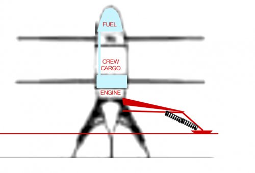
Vertical flight: All existing contrarotating helicopters have their C of G well below both rotors, so fuselage rotation can be controlled by differentially changing average pitch angle (therefore torque) between the two rotors. As your design has a C of G between the rotors, attempts to control Fuselage rotation this way would cause the centre of lift to change height significantly relative to the C of G and therefore stability.
Horizontal fight: As discused in previous post the rear/lower rotor provides considerably less lift/thrust than the front/upper rotor so in vertical flight the centre of lift may still be above the C of G regardless of differential pitch angles. However in horizontal flight attempts to control fuselage spin through this method might result in change of centre of lift between front and rear therefore inducing drastic pitching unless some other factor is in play to counteract this.
Transitional flight: I haven't even considered how the above would affect your concept for transitional flight.
I'm sure you must have considered this point and I will be fascinated to read your solution.
Cheers, Woody
PS. You mentioned that pitch angle (cyclic, collective etc.) will be controlled by 'fast-acting servo's. Has this ever been achieved on a conventional helicopter?, and how does it compare to a conventional swash plate in respect to: weight, cost, reliability, power consumption?, or would a swash plate simply not work for horizontal flight?
Hi Woody,
Thanks for your interest.
I think that you are trying to think through the stability of this craft based on principles of directional stability that apply to fixed-wing aircraft. Fixed-wing aircraft are conditionally directionally stable (you are trying to get the right conditions), this craft is neutrally directionally stable, and helicopters are directionally unstable. In an attachment to an earlier post I said,
"The author flew a toy model of the craft in the 1950s as shown in Figure 1 above. When the rubber band was wound up and the craft was tossed, it flew in the direction it was pointed, horizontal, vertical or at any angle in between. As it flew it often changed its heading a small amount. Its flight path consisted of several straight-line segments with small heading changes between the straight-line segments. This behavior can be described as neutral directional stability; the direction was apparently altered by minor air turbulence and a new direction continued with no memory of the previous direction."
I did not understand what I was looking at then, but I knew it was not flying like a hand-tossed glider. About 11 years ago I spoke to Professor Steven R. Hall of the MIT Aero Department and asked him about the craft's directional stability. After reflecting on it overnight he said that it would have neutral directional stability. Sometime after our conversation I realized that this is was, in fact, what I had seen demonstrated.
Well, neutral directional stability is easier to control than unstable directional stability - so it should be easier to automatically control than a helicopter. But we live in a world where all kinds of wild things are done with intelligent controls. I understand that even a bicycle has now been steered and balanced in a close loop system. You are probably aware that the trick of riding a bicycle is initially steering in the wrong direction in order to develop tilt to enable turning in the desired direction. This behavior can be expressed in equations of motion and computer controlled.
To get to your question. I expect to have strain gages or the like at the root of each rotor blade as well blade pitch angle sensors and rotor angle and rotor torque sensors. Control circuitry will adjust each rotor blade's pitch angle continuously to give the desired blade lift as sensed by the strain gages. And rate gyros in the craft will immediately sense any tendency of the fuselage to rotate about its axis. So the roll rate of the fuselage will be under immediate, direct and continuous computer control. This will be true in hover, transition and cruise.
Such a system will also contain accelerometers and can control accelerations in all directions. It will be able to accommodate all kinds of irregular conditions such as, in horizontal flight (cruise), a CG shift so that the forward rotor is more heavily loaded than the aft rotor or, in the case of gusts from clear air turbulence, keeping the accelerations very low inside the craft - as well as all combinations of conditions.
About using electric motors to control rotor blade pitch angles. In 2003 ago I was having trouble convincing my patent attorney that I had something unique because of the existing patent HELICOPTERS WITH COAXIAL ROTORS OF CONVERTIBLE TYPE IN PARTICULAR, by Tassin de Montaigu, Patent No. 4,123,018, dated Oct. 31, 1978. He thought that this was not far from what I am doing and recommended against a patent application. Well, I then thought that driving and controlling the pitch angles of the rotor blades with servo motors might be what I could patent, so a search was done on that. Of course, it had not been done a craft like mine, but there were lots of patents on electrically controlling the pitch of rotor blades on helicopters - a well plowed field.
When I started the mechanical design of my prototype I started out planning to use a swash plate means of varying cyclic and collective pitch. I wanted something quick and dirty to demonstrate the flight principles, but I
found it very awkward to try to use a swash plate approach because the hub diameter is large and an open space is needed inside the hub. You can see that the diameter, as it were, of the swash plate would have to be very large. So, knowing the advantages of direct servo drive, I decided to go with that approach. I haven't done a cost comparison, but I imagine it is more expensive than swash plates where swash plates can be used - but my craft is probably not one of those cases. However, if this craft is ever built in quantities like city buses, the cost per blade for the servo drive will come way down.
There are neat things that can be done with a servo per rotor blade. Higher order harmonic control is possible. Suppose in transition the craft had a very high peak lift coefficient in the advancing blades and that it would be nice to be able to modify that. So rather than asking the servo for a sine wave of lift versus rotation, the control could flatten the peaks of the sine waves while keeping the same area under the sine waves - all with little or no penalties. Of course huge reductions in lift peaks can't be realized, but a small and free reduction might be very attractive. Or how about this: drive the rotor blades so as to waste power. Normally I hope to convert altitude and speed near the end of a flight to a greater distance traveled by coasting, but under some conditions it may be necessary to settle quickly as in emergency autorotation. It will be easy to overspeed the rotors by asking them to windmill and quickly absorb a lot of altitude energy. How could one dump some of this energy? By alternating the pitch of the rotor blades so that one is lifting near the maximum lift coefficient and the next one is opposing that lift, trying to sink the craft, and so forth around the rotor. (An even number of rotor blades is needed to do this trick.) I think of this as being like an egg beater, churning the air. You could never do this with a swash plate drive.
Reliability of servo drives. Most new aircraft work their control surfaces "fly by wire". Redundancies are built in. Soon even cars will be steered without a mechanical backup. So I feel that with proper design, aiming for the highest possible reliability, the servo drives for rotor blade pitch will be highly reliable, maybe better even than mechanical drives. There is also a lot that continues to be done with the software in digital controls (which these would be) to make the software ultra-reliable by self-checking, redundancies, etc.
Power consumption: modern servo drives use switching power amplifiers with this curious characteristic: most of the energy used to accelerate a load is recovered when the load is decelerated; the power supply voltage actually gets "pumped up" from the recovered energy. So accelerating and decelerating the pitch inertia of the rotor blades should not waste much energy.
Sincerely,
John Lawrence

")