- Joined
- 26 May 2006
- Messages
- 32,688
- Reaction score
- 11,910
circle-5 said:Douglas Model 2229 SST flight deck model.
Very nice displaying my dear Circle-5.

circle-5 said:Douglas Model 2229 SST flight deck model.
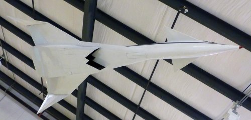
circle-5 said:This 1/10-scale factory model was shown to airline customers interested in offering Mach 3+ commercial routes. It is now displayed at the Santa Monica Museum of Flying
")
galgot said:Thanks.
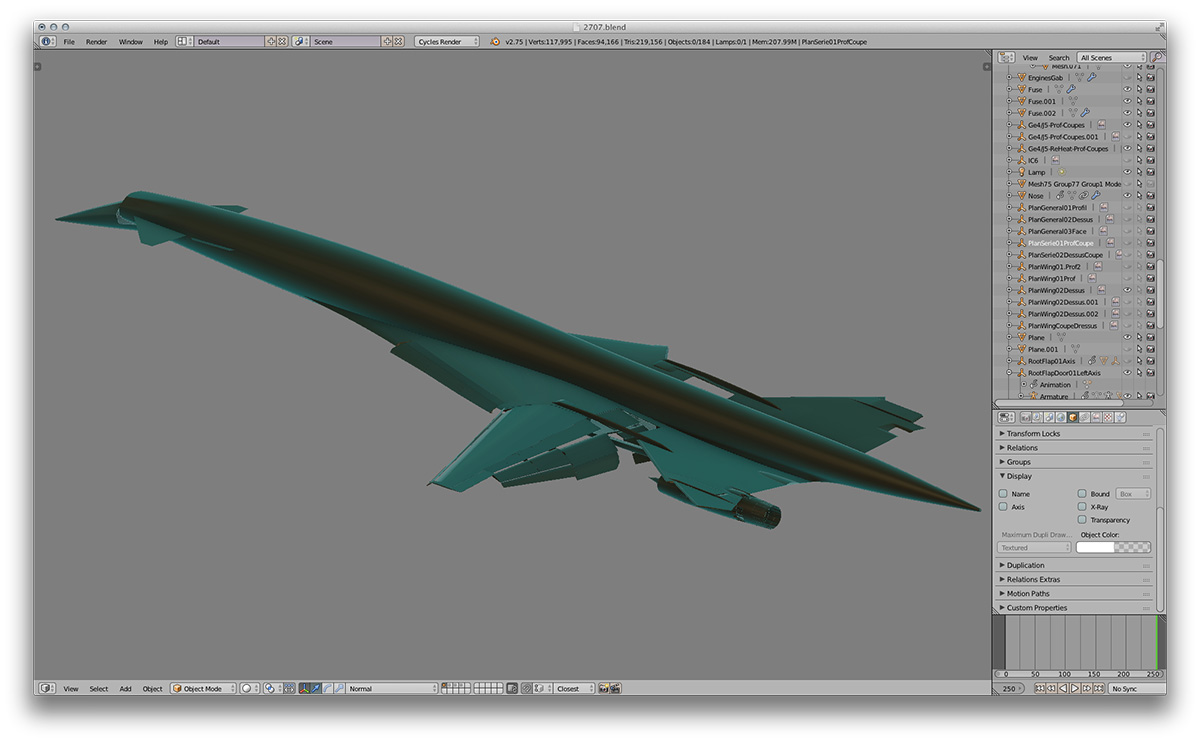
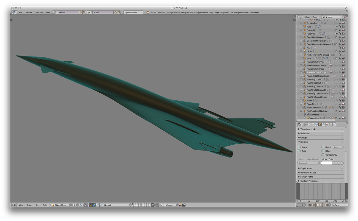
Finished the front LG yesterday :
http://galgot.free.fr//transit/FG2707.jpg
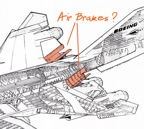
So… Could you confirm these things in my previous post are air Brakes ? or some engine service panels ?
I'll like to be able to do some renders in landing configuration, and maybe these would be open if they are indeed air brakes.
galgot said:Thanks, I think I finally found out.
Yesterday I downloaded the Boeing SST patent 3447761 :
http://www.secretprojects.co.uk/forum/index.php?topic=3794.msg29793#msg29793
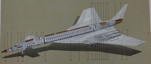
Something I didn't had before. Even though it describes the 2707-100 it includes a precise description of all control surfaces.
Apparently these are "auxiliary elevators" (!). Moving upward only, the engines being just under it, which is consistent with your observation of these giving upward pitch MaxLegroom.
Thinking now also that it would be a bad idea to put air brakes just in front of the GE4 engines reverse exhaust , as both would be used approximately at the same time, the reverses would tear of the air brakes…
On the patent it shows these kind "auxiliary elevators" over each engines, but on the 2707-200 it seems they discarded the ones over the outboard engines.
Worked on the wing root flaps, will post some other screenshots in the users artwork section later
cheers
fightingirish said:15 b/w pictures of US Supersonic Transport (SST) projects at Klassiker der Luftfahrt.
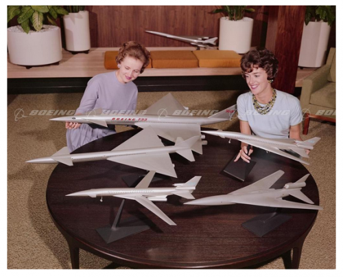
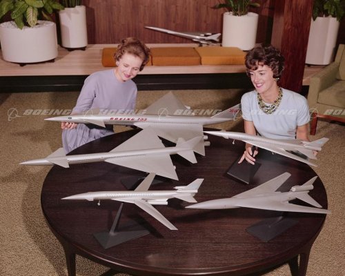
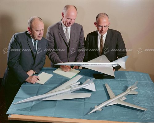
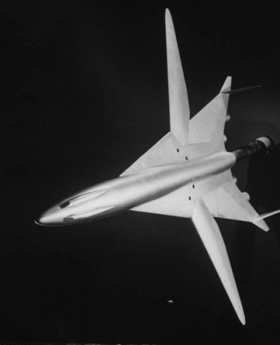
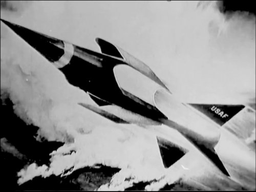
North American Aviation NAC-60, Boeing 2707 and Lockheed L-2000
Link: Klassiker der Luftfahrt: Supersonic - US-Überschallprojekte der 60er
Looks Convairish. -SPhesham said:fightingirish said:15 b/w pictures of US Supersonic Transport (SST) projects at Klassiker der Luftfahrt.
North American Aviation NAC-60, Boeing 2707 and Lockheed L-2000
Link: Klassiker der Luftfahrt: Supersonic - US-Überschallprojekte der 60er
What was this,or from which company ?.
Steve Pace said:Looks Convairish. -SPhesham said:fightingirish said:15 b/w pictures of US Supersonic Transport (SST) projects at Klassiker der Luftfahrt.
North American Aviation NAC-60, Boeing 2707 and Lockheed L-2000
Link: Klassiker der Luftfahrt: Supersonic - US-Überschallprojekte der 60er
What was this,or from which company ?.
hesham said:fightingirish said:15 b/w pictures of US Supersonic Transport (SST) projects at Klassiker der Luftfahrt.
North American Aviation NAC-60, Boeing 2707 and Lockheed L-2000
Link: Klassiker der Luftfahrt: Supersonic - US-Überschallprojekte der 60er
What was this,or from which company ?.