New stealthy VTOL aircraft- more efficient and much faster

Flyingeagle

ACCESS: Restricted
Joined
9 October 2015
Messages
14
Reaction score
0
We are studying a new VTOL aircraft with an annular lift fan as shown in the picture. The aircraft is more efficient than helicopters with power loading of 7.4 lbs/hp (4.5 kg/kw) at the disc loading of 28.37 lbs/ft2 (138.5 kg/m2) without ground effect. When the distance from the aircraft to the ground is 10 m, the figure of merit reaches 0.832 with the power loading of 8.5 lbs/hp (5.2 kg/kw). The maximum cruise speed can reach 0.75 Ma, much faster than helicopters and tiltrotors. The aircraft is also stealthy and quiet. Here are the research articles:

http://www.mdpi.com/2226-4310/3/4/30
http://www.mdpi.com/2226-4310/2/4/555
 

Attachments

  • transition2.jpg
    transition2.jpg
    344.1 KB · Views: 490
  • outlook.png
    outlook.png
    126.5 KB · Views: 475
So .... Schriever had it right from the get-go?

David
 
Flyingeagle said:
We are studying a new VTOL aircraft with an annular lift fan as shown in the picture. [...] The aircraft is also stealthy [...]

I'm confused by that statement.

If the aircraft has a huge spinning fan blade at its center, I'm not sure it can be that much stealthy. Unless the fan is completely covered with something like an S-duct, but I suppose this is not the case (?).
 
;D
 

Attachments

  • Incredibles-Velocipod.jpg
    Incredibles-Velocipod.jpg
    487.1 KB · Views: 390
Ah..
 

Attachments

  • dejavu.jpg
    dejavu.jpg
    8.3 KB · Views: 403
  • avro-project Y.jpg
    avro-project Y.jpg
    45.1 KB · Views: 354
The lift fan will stop working and be closed by louvers in cruise flight as F-35B, so it is stealthy.

Here is the latest paper:

http://www.mdpi.com/2226-4310/3/4/35
 
Constant radius curves (like cylinders or discs) are inherently non-stealthy shapes. They scatter signals in all directions, which is exactly what you don't want in a stealth aircraft.
 
Flyingeagle said:
The bottom can be flat like a plate.

How is that supposed to help? The leading edge is still an isotropic scatterer (look it up).
 
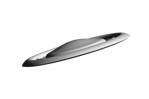
^fwiw, this "leading edge" since it is a curved edge would have an edge diffraction scattering contribution (assuming a PEC/perfect electrical conductor) approximately on the order of "radius * wavelength / (2*pi)", as taken from approximation based on MEC/method of equivalent currents (ref: equation 14.12, "Radar Cross Section, 2nd Ed.", Knott)

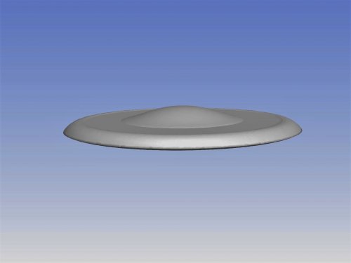
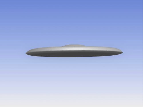
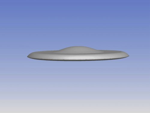
the aircraft in the paper appears to have a radius on the order of 8 m, so at a nominal x-band wavelength of 0.03 m the edge diffraction contribution of the curved edge would be ~0.038 sqm, and as it is disc shaped this contribution would be present from any viewing angle on the plane of the disc...

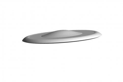
added to this (ie. by phasor addition, where the maximum coherent sum would be the square of the sum of the square roots of each rcs contributor) would be the contribution of the curved surfaces which lead away from the edge in the upwards and downwards directions (ie. the surfaces which form the ogive cross section of the outer ring as it appears in the paper)... these backscatter contributions would be in the non-specular direction since the view angle (ie. in the plane of the disc) is not normal to the curved surfaces which would thus make them smaller than the specular backscatter from either a doubly curved surface (eg. spheroid) , or a singly curved surface (eq. cylinder)...

contributions by surface waves, ie. creeping and travelling, are not included as these are on the order of the square of the wavelength which would make them around -16 dB smaller (ie. at x-band of 0.03 m) than the contribution of the curved edge diffraction alone, so they're being ignored for approximation since their contribution is much smaller than that for the edge diffraction... I'ld guess if they were to actually build something like this they would use RAM to reduce the much larger edge diffraction contribution (ie. to attempt to get a -20 dB reduction or so via RAM), as well as to try and reduce surface wave contributions...
 
The first image is actually phase 1.

Phase II is to extend the engines further from the center fuselage and expand that center fuselage. Phase II will also introduce an exciting new engine technology that will be 'out of this world'!


;)
 

Attachments

  • Screen Shot 2016-10-20 at 3.22.27 AM.png
    Screen Shot 2016-10-20 at 3.22.27 AM.png
    492.5 KB · Views: 26
  • Screen Shot 2016-10-20 at 3.14.56 AM.png
    Screen Shot 2016-10-20 at 3.14.56 AM.png
    246.3 KB · Views: 212
this design remind of something

but what ?
Ah Yes also a revolutionary VTOL with some stealth from 1960s
the Infamous Avro Canada VZ-9AV «Avrocar»...
...For lame Aircraft, it was hell of a Hovercraft

index.php
 
I see shades of a Lindberg design: http://www.fantastic-plastic.com/Lindberg%20Flying%20Saucer%20Page.htm

Martin
 
The aircraft looks like a Avrocar, but the principle is completely different. If Avrocar were simulated by CFD, it would never be built. With today's technology, CFD simulation will show Avrocar does not work.
 
With the duct closed:
 

Attachments

  • duct-closed.jpg
    duct-closed.jpg
    110.4 KB · Views: 202
  • duct-clos.jpg
    duct-clos.jpg
    97.7 KB · Views: 201
  • duct-closd.jpg
    duct-closd.jpg
    102.7 KB · Views: 189
  • ductclose.jpg
    ductclose.jpg
    69.9 KB · Views: 187
Flyingeagle said:
http://www.mdpi.com/2226-4310/3/4/30

No jet engine is that slim. This looks like primitive pulsing ramjets and thus casts severe doubts about the seriousness of the "studying".

Also, this kind of VTOL was tested long ago already, safe for jet engines.
 
The jet engines should be turbofan, which can be made slim if you want. The picture only shows vectored jet for attitude control in transition from VTOL to aerodynamic flight, not a real jet engine.
 

Attachments

  • transition.jpg
    transition.jpg
    225.5 KB · Views: 163
A flying saucer shape can be reasonably stealthy given the correct profile. It needs to come to a sharp point rather than have a plain curve, something like the leading edge of the B-2 wing. Given reasonable materials on the outer rim, it would be pretty low RCS in all directions with no significant spikes. However, adding control panels, access panels and the like would be pretty tricky.
 
Back
Top Bottom