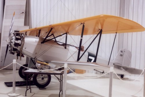
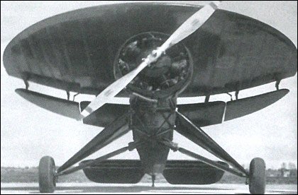
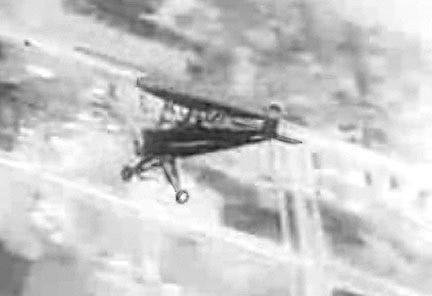
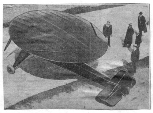
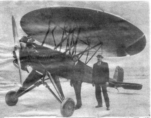
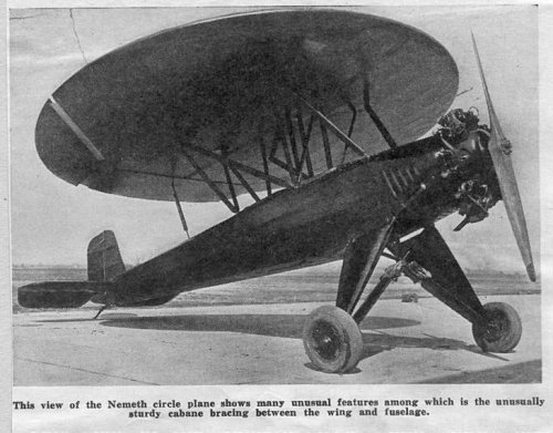
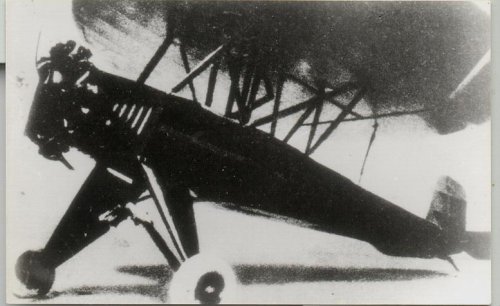
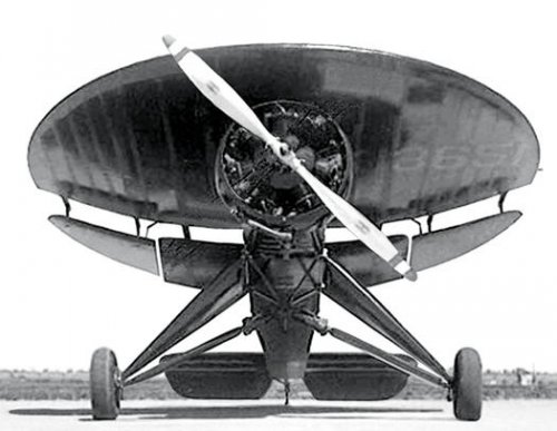
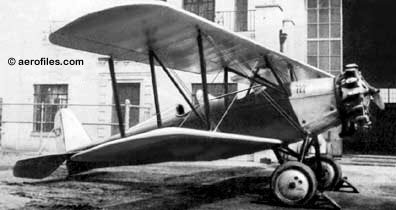
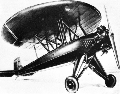
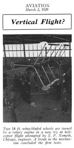
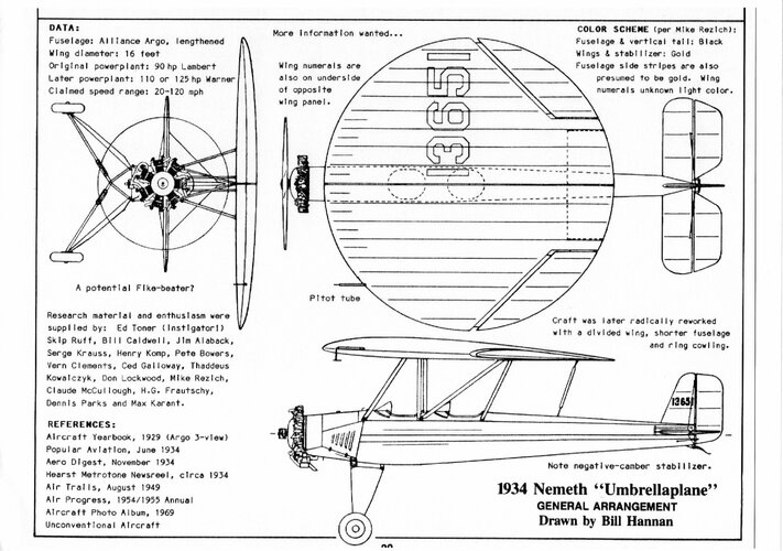
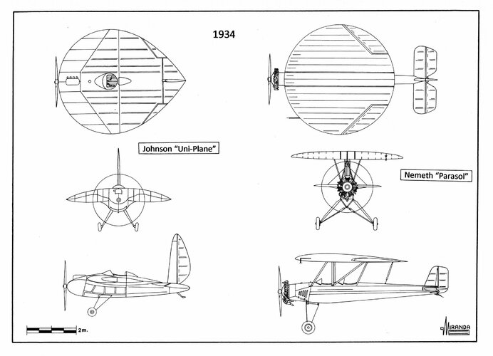
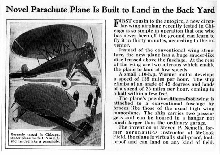
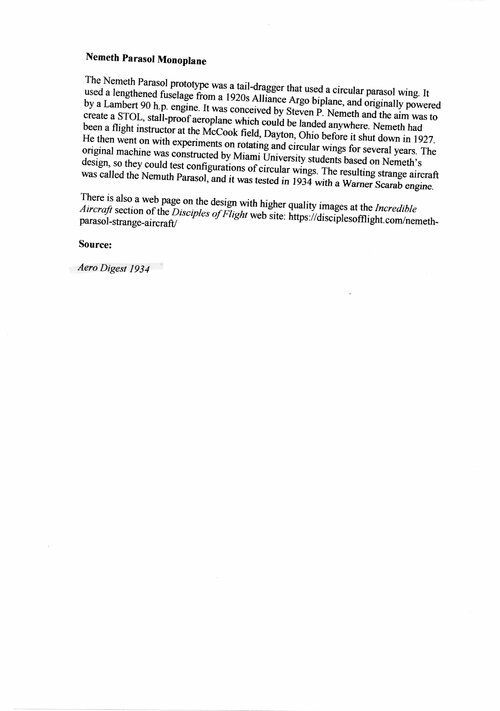
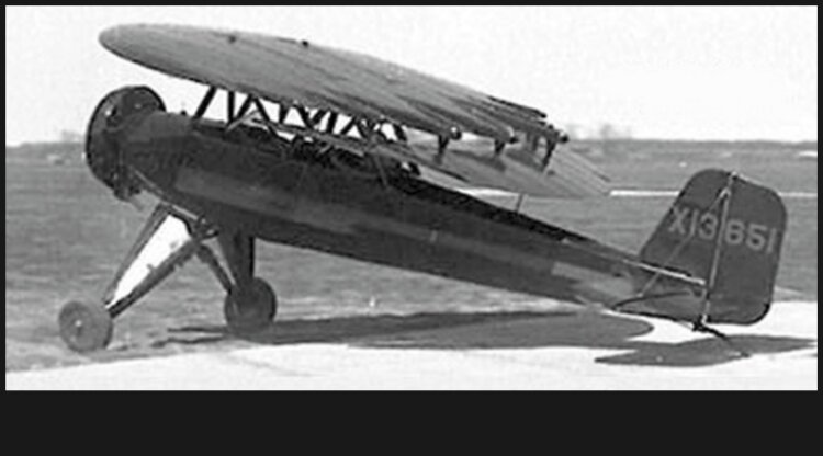
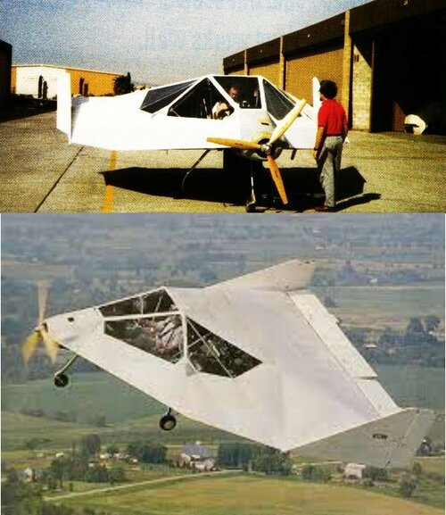
Hi friends, about the ever-fascinating and intriguing matter of disc-shaped wing aircraft I found some very old paper clippings depicting the Nemeth aircraft, I think designed by the same Paul Nemeth that in the following years designed and built an helicopter (already subject of posts in this blog). My clippings are dated March 1934 and the subject is an experimental aircraft apparently named Circle (and not Umbrellaplane as some sources reports) designed by Stephen Paul Nemeth, veteran Chicago aeronautical engineer. Below there is an abstract from e Russian webpage I think is a copy of the Aerofiles one. Another design called the Umbrellaplane (sic) was also known as the Roundwing. It was built in 1934 = 2pOhwM; 90hp Lambert; span: 16'0" length: 20'0" v: 120/95-100/20-25. Circular wing on a lengthened Alliance Argo fuselage for STOL performance [X13651]— initial experiments by Paul Nemeth with rotating wingforms go back to 1929. Designed by Nemeth and built by students at Miami University (OH) to test circular wing configuration. Repowered with 120hp Warner Scarab, later reworked as divided wing. Name has been seen spelled Nuneth. For the aircraft we found also the names Roundwing and Backyard Flyer. The fuselage is that from the Alliance A-1 Argo light aircraft (I also enclosed a photo of it) with the original 90 HP Lambert engine replaced by a 125 HP Warner; in fact, usually Argo had a Hess Warrior seven-cylinder radial, rated at 125 HP. Naturally, the wing, perfectly round, is totally new. This strange machine was really flown, as we have a still from film footage, reaching 110-120 mph (the designer claimed 135), cruising at 95-100 mph and landing at 20-25 mph in a 25 ft area, descending with a 60° angle. The news of the first fligh is dated March 21, 1934. I ever heard from aeronautical engineers that this type of low aspect ratio wing offer very marginal performance, except for STOL, but in about a century of flight the disc-shaped aircraft every so often resurface Nico

You are using an out of date browser. It may not display this or other websites correctly.
You should upgrade or use an alternative browser.
You should upgrade or use an alternative browser.
Nemeth Umbrellaplane ("Roundwing") and other projects
- Thread starter Nico
- Start date
- Joined
- 25 June 2009
- Messages
- 13,746
- Reaction score
- 2,932
- Joined
- 26 May 2006
- Messages
- 32,646
- Reaction score
- 11,831
Hi,
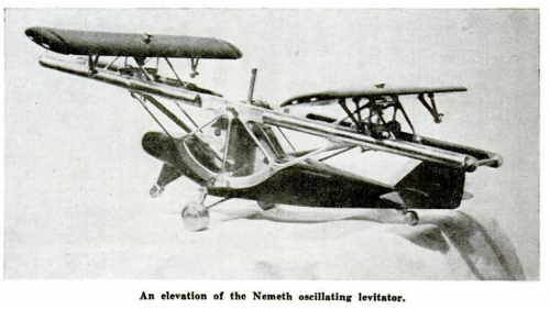
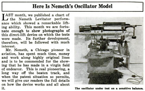
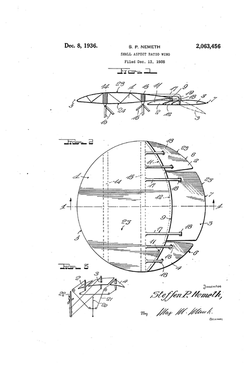
here is a strange airplane Model with levitator,designed by Mr. Nemeth
in 1935,I can't understand its work well ?,page 300,I think he was the same designer here;
here is a strange airplane Model with levitator,designed by Mr. Nemeth
in 1935,I can't understand its work well ?,page 300,I think he was the same designer here;
Flying Magazine
books.google.com.eg
Attachments
Last edited:
- Joined
- 25 June 2009
- Messages
- 13,746
- Reaction score
- 2,932
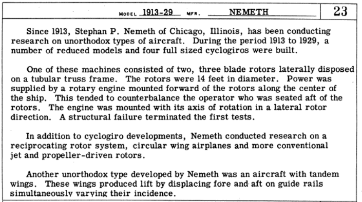
Steven P. Nemeth's aviation career is not very well known. Besides a couple of cyclogyro projects in the 1920s and his obvious Roundwing of 1934 (also known as the Umbrellaplane), Nemeth also set up the Nemeth Helicopter Corp. after World War 2 and developed a two-place anti-torque helicopter with ramjets at the tips of the single rotor's two blades. Apparently the machine was finished and was tested in 1947. Unfortunately, I have never been able to find a photo of it. Could anyone help?
- Joined
- 25 June 2014
- Messages
- 1,564
- Reaction score
- 1,453
hesham said:Hi,
here is a strange airplane Model with levitator,designed by Mr. Nemeth in 1935,I can't understand
its work well ?,page 300,I think he was the same designer here;
https://books.google.com.eg/books?id=Ji_ty9AEz58C&printsec=frontcover&hl=ar&source=gbs_ge_summary_r&cad=0#v=onepage&q&f=false
It looks as if it is basically a tandem-wing ornithopter. The longitudinal frame is driven to oscillate like a see-saw. Each wing therefore moves alternately up and down, just like a flapping bird except the wings are out of sync. With careful cycling of their angles of attack, the wings can each contribute fairly constant lift but take it in turns to provide the thrust on the downstroke, giving the pilot a reasonably smooth ride.
It's clever and it's a lovely idea. I want one that's painted up like a Chinese dragon and designed to be ridden from a saddle!
There is an added subtlety in nature, in that many if not all birds also move their wings a little forward and backward out of phase with the flapping so they move more in a figure-eight than simply up-and-down, It improves STOL performance and, I think, makes the thing more efficient while allowing the body to remain steadier. It is not clear from the limited information given whether Nemeth slides his wings fore and aft to mimic that.
And I think there is one potential drawback. The power source for the see-saw must react against the fuselage or some other massive body and make it rock in the other direction. Compensation cannot be integrated with the lift distribution on the see-saw or you would have perpetual motion. So it would still be a rocking ride. A bit like riding a dragon, I suppose
")
- Joined
- 25 June 2009
- Messages
- 13,746
- Reaction score
- 2,932
- Joined
- 31 July 2013
- Messages
- 546
- Reaction score
- 1,072
Hi Stargazer, only four years late but here's a pic of the Nemeth Helicopter, taken from https://sites.google.com/site/stingrayslistofrotorcraft/nemeth-helicopter. This is also on this site at https://www.secretprojects.co.uk/threads/nemeth-ramjet-helicopter-design.606/ along with a second image of an earlier iteration of the design I would surmise.


John Frazer
I really should change my personal text
- Joined
- 1 January 2018
- Messages
- 24
- Reaction score
- 33
A common misconception is that these were draggy because of the very-low aspect-ratio and its STOL performance, but this is not demonstrated in very many planes of the type.
This plane follows the Arup S-2 which demonstrated the type and that it does not inherently always carry around the burden of the huge wing-tip vortices they're intended to produce at very low speeds, very high A. The "parachute lift" effect and attendant excessive drag is elective and temporary, and well known and documented.
Aspect ratio = span^2/area. if under 3, in order to fly slowly at high A, the vortices wrap around the wing capturing a "bubble" of low pressure above it (while A is compressing air under it, and increasing effective camber). At the same time, the vortices are trapping the flow from the front of the wing, keeping it from separating and providing strong smooth flow to the controls. They don't stall, as in departing uncontrollably from flight because of loss of lift and controls. At stupid slow speed and high nose-up, they'll be going nowhere but down, but they're still flying.
Zimmerman found that near the aspect ratio that the Arup was built for, the effect is maximized, and that's what he chose the shape of the V-173 for, as the starting point for his interest in a VTOL tail-sitter.
The Nemeth with less power than the original could keep up with it, was faster with the original power.
The Arup S-2 was 780 lbs, flew 85 kts on 37hp engine, with 18 kts landing speed. With steep climb, super-STOL, stall proof. The S-4 was ~1150lbs, 70 hp, 100 kts.
Wainfan demonstrated cross-country to Ohskosh in the Facetmobile; 100 kts on 40 hp with 340lb useful load. It could stay in flight at <16kts (his pitot tube couldn't read any slower).
I've seen a few equations and heard several explanations why very-low aspect-ratio is poor or inefficient: If this alleged inefficiency isn't manifested in power vs speed or fuel vs range, then what is it?
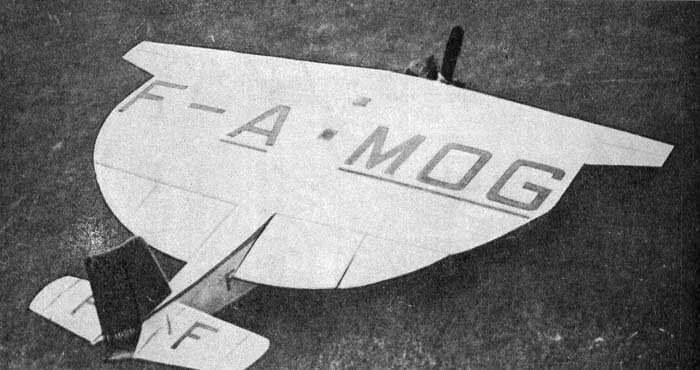
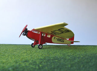
See also the Farman 1020 of the same time. Like the Nemeth "parachute plane", built on the fuselage of a known successful plane, faster than original, STOL, stall-proof.
Zimmerman wrote about the parachute lift effect for NACA and UAC, and Wainfan wrote about it for NASA, who was looking for a re-entry vehicle and at the novel, simplified construction.
This plane follows the Arup S-2 which demonstrated the type and that it does not inherently always carry around the burden of the huge wing-tip vortices they're intended to produce at very low speeds, very high A. The "parachute lift" effect and attendant excessive drag is elective and temporary, and well known and documented.
Aspect ratio = span^2/area. if under 3, in order to fly slowly at high A, the vortices wrap around the wing capturing a "bubble" of low pressure above it (while A is compressing air under it, and increasing effective camber). At the same time, the vortices are trapping the flow from the front of the wing, keeping it from separating and providing strong smooth flow to the controls. They don't stall, as in departing uncontrollably from flight because of loss of lift and controls. At stupid slow speed and high nose-up, they'll be going nowhere but down, but they're still flying.
Zimmerman found that near the aspect ratio that the Arup was built for, the effect is maximized, and that's what he chose the shape of the V-173 for, as the starting point for his interest in a VTOL tail-sitter.
The Nemeth with less power than the original could keep up with it, was faster with the original power.
The Arup S-2 was 780 lbs, flew 85 kts on 37hp engine, with 18 kts landing speed. With steep climb, super-STOL, stall proof. The S-4 was ~1150lbs, 70 hp, 100 kts.
Wainfan demonstrated cross-country to Ohskosh in the Facetmobile; 100 kts on 40 hp with 340lb useful load. It could stay in flight at <16kts (his pitot tube couldn't read any slower).
I've seen a few equations and heard several explanations why very-low aspect-ratio is poor or inefficient: If this alleged inefficiency isn't manifested in power vs speed or fuel vs range, then what is it?
See also the Farman 1020 of the same time. Like the Nemeth "parachute plane", built on the fuselage of a known successful plane, faster than original, STOL, stall-proof.
Zimmerman wrote about the parachute lift effect for NACA and UAC, and Wainfan wrote about it for NASA, who was looking for a re-entry vehicle and at the novel, simplified construction.
Attachments
Last edited:
Deltafan
ACCESS: Top Secret
- Joined
- 8 May 2006
- Messages
- 1,569
- Reaction score
- 1,810
- Joined
- 11 March 2012
- Messages
- 3,016
- Reaction score
- 2,687
Conventional CFD fail to consider the complex airflow in wing tip vortices.A common misconception is that these were draggy because of the very-low aspect-ratio and its STOL performance, but this is not demonstrated in very many planes of the type. ....
Aspect ratio = span^2/area. if under 3, in order to fly slowly at high A, the vortices wrap around the wing capturing a "bubble" of low pressure above it (while A is compressing air under it, and increasing effective camber). At the same time, the vortices are trapping the flow from the front of the wing, keeping it from separating and providing strong smooth flow to the controls. They don't stall, as in departing uncontrollably from flight because of loss of lift and controls. At stupid slow speed and high nose-up, they'll be going nowhere but down, but they're still flying. ....
Wainfan demonstrated cross-country to Ohskosh in the Facetmobile; 100 kts on 40 hp with 340lb useful load. It could stay in flight at <16kts (his pitot tube couldn't read any slower).
I've seen a few equations and heard several explanations why very-low aspect-ratio is poor or inefficient: If this alleged inefficiency isn't manifested in power vs speed or fuel vs range, then what is it? ....
Barnaby Wainfain discovered that wing tip vortices (AR less than 2) tend to try to cross the centerline, and when they collide, they cancel out each other making the downstream airflow far less turbulent aka. a flatter lift-to-drag ratio. That is one of the reasons that low AR airplanes do not work well with rudders at mid-span.
Another advantage is that the long chord (17 feet on Facetmobile) yields much higher Reynolds numbers, which in turn lift better and produce less drag than short chords. As an aside, few amateurs can build a precise wing airfoil with a chord of less than 4 feet (130cm).
Bart VerHees enjoys similar economies of scale with his Verhees Deltas.
Wainfain had lectured on the subject at several EAA Airventure Airshows (typically at Oshkosh, Wisconsin during late July).
Wainfain is currently in the later stages of building the prototype FMX-7 Facetmobile in Independence, Oregon. As of August 2023, most of the airframe is complete and he is mating the outer wing panels with the center fuselage.
Vortex lift is not unique to low AR planforms as swept-wings demonstrate similar vortex lift at high angles of attack. Leading edge sweep angle is the key.
Withold Kasper demonstrated similar high angle-of-attack, low-speed, vortex lift with his swept-wing, BKB tail-less sailplane. Later versions even had a panel hinged at the leading edge to encourage vortices to develop immediately aft of the leading edge.
Vortex lift is mainly a function of leading edge configuration. Delta-winged fighters can be more efficient at shallow angles of attack, but develop massive amounts of drag at high angles of attack. In the extreme, you get a sharply-swept delta like the Concorde SST airliner than developed such massive amounts of drag at low-airspeeds and high angles-of-attack that it could not "power" itself out of too slow an approach. Hence Concorde pilots spent plenty of time training to "fly by the numbers." An undesirable side effect was the massive amounts of thrust needed at low-airspeeds which prompted too many complaints about noise pollution from neighbors.
Last edited:
Similar threads
-

-

-

-
-
Richard Transatlantic Amphibian Project
- Started by hesham
- Replies: 12