Augmented cooling radiators

ford_tempo

ACCESS: Confidential
Joined
31 January 2011
Messages
78
Reaction score
8
ford_tempo

Cooling drag was an area of strong interest in aircraft powered by piston engines as it was an area that strongly affected performance: Whether it be to simply be streamlined and low-drag, or as in the meredith effect, designed to actually counter drag with thrust.

If I recall the figures with the P-51 radiator, a 2 kN figure would be something like 500 pounds of thrust: I'm not sure what the drag of the assembly was, but I've been told drag usually was greater than thrust.
 
What kinds of fans, heat exchangers and other gadgets have been tried, in order to make piston-engine cooling radiators more effective and hence smaller? I only know of a couple:
  • The humble belt-driven fan is common enough, especially on ground vehicles, and helps most when developing high power at at low speed, such as a lorry climbing my local escarpment from the Severn valley to the Cotswolds.
  • The Meredith radiator is a kind of simple thermal ramjet (i.e. an asymmetric duct) and works best at speeds above a few hundred mph. Even the first half-baked (sic) production example in the Spitfire was half the size of the conventional radiator in the Bf 109, and generated a tiny bit of ramjet thrust to boot. It came into its own on the P-51D Mustang.
On this theme, a turbocharger-like arrangement occurred to me. An intake compressor feeds a heat exchanger (radiator) which feeds a turbine with hot, expanded air to spin up the compressor. This would need something like a belt drive to work at low speeds, and/or sufficient ram-air effect at high speeds. These drawbacks can be overcome by combining it with a conventional turbocharger. The compressor output is now split between piston engine and heat exchanger, and afterwards recombined to feed the turbine. Engine waste energy drives it throughout, so cooling ratchets up automatically according to power output.
Many weird and wonderful variations on turbo-augmented power output have been tried. It seems so logical to extend such ideas to cooling systems that I cannot help but wonder if any, and/or other bright ideas in the same vein, have already been tried?
 
The most common solution on vehicles today is the electric fan. This allows you to control the fan thermostatically, and have it run based on engine load (=heat production) and vehicle speed (=amount of air coming through the radiator). That minimizes the amount of energy you spend running the fan. The dynamo->fan motor route is also efficient.

in fact, manufacturers are moving other engine accessories to electric drive as well. This started with AC and power steering.
 
Last edited:
Fw190 etc. with geared fan for forced air cooling. Many similar forced air cooling systems exist.

For your scheme with a compressor, this will increase the temperature of the the flow and make the heat exchanger less effective, although to be fair this is also true of fans but these just have a much lower pressure ratio and hence lower temperature increase.

I'm not sure what would stop a turbocharger driven forced air cooling fan scheme - probably where you need to locate all the bits e.g. may need quite a complicated drive shaft to the fan as it's probably best in a different place to the turbocharger. This where a more modern electric offtake/motor comes in
 
Townend rings NACA cowlings serve this purpose on the radiator fins of air-cooled radials.

Many WW-1 German aircraft used airfoil-shaped radiators embedded in the upper wind, where, presumably, drag was reduced and cooling improved by the pressure differential on each side of the airfoil.

Surface evaporative cooling systems sent the other way and made the surface of the aircraft serve as huge radiators and coolant condensers.
 
Hi,

The Meredith radiator is a kind of simple thermal ramjet (i.e. an asymmetric duct) and works best at speeds above a few hundred mph. Even the first half-baked (sic) production example in the Spitfire was half the size of the conventional radiator in the Bf 109, and generated a tiny bit of ramjet thrust to boot. It came into its own on the P-51D Mustang.

Well, the energy-recovering radiator was actually patented as "jet radiator" by Prof. Junkers in 1915 already, and was fully appreciated by the German aviation industry, including by Prof. Messerschmitt, who in a 1930s' speech praised Junkers invention as invaluable for high speed flight.

Regarding the Spitfire, here's a quote from David Lednicer's article "WW2 Fighter Aerodynamics ":

"Supermarine is often regarded as being one of the first companies to make use of the breakthroughs made by Meredith at RAE Farnborough in the design of ducts for cooling systems. In fact, the Spitfire's radiator ducts were designed using these guidelines. However, the VSAERO calculation indicates the boundary layer on the lower surface of the wing is ingested by the cooling system inlet. Running into the severe adverse (increasing) pressure gradient ahead of the radiator, the boundary layer separates shortly after entering the duct, resulting in a large drag penatly. Experimentally, it was determined that the Spitfire cooling system drag, expressed as the ratio of equivalent cooling-drag power to total engine power, was considerably higher than that of other aircraft tested by the RAE. This was attributed to the 'the presence of a boundary layer ahead of the duct tends to precipitate separation and makes the ducting problem more difficult'. Similar problems are present on the early model Messerschmitt Bf 109, up through the E model. A complete redesign of the cooling system, during development of the Bf 109F, resulted in the use of a boundary layer bypass duct, which significantly improved the pressure recovery at the radiator face."

Regards,

Henning (HoHun)
 
Thanks all for those comments. I'd just note that what I mean by "augmentation" is some kind of additional energy input. Simple aerodynamic shaping to channel the airflow is not really augmentation, but a useful addition to the discussion nonetheless.
 
Hi,

Thanks all for those comments. I'd just note that what I mean by "augmentation" is some kind of additional energy input. Simple aerodynamic shaping to channel the airflow is not really augmentation, but a useful addition to the discussion nonetheless.

Well, generally, compressing air increases its temperature, as does any kind of "additional energy input", which means that it's generally a bit counterproductive. However, some engine installations had an engine-driven fan to improve aerodynamics, most prominently the Fw 190A, so it's not impossible to make it work.

Regards,

Henning (HoHun)
 
Thanks all for those comments. I'd just note that what I mean by "augmentation" is some kind of additional energy input.
The general issue with this that the additional energy input warms up the flow, reducing the temperature differential to the coolant and hence reducing the heat exchanger effectiveness.

Where in the flight regime do you want augmented flow? At high altitude / max speed then ram air cooling is sufficient due to speed = flow rate and low temperature. However its probable that climb or manouevre at low altitude is the driving case where you have less flow rate and a lower temperature difference - hence fan boost to maintain similar flow rate throughout the flight envelope.
 
The general issue with this that the additional energy input warms up the flow, reducing the temperature differential to the coolant and hence reducing the heat exchanger effectiveness.
Fans and the Meredith effect both augment the airflow energy by speeding it up, not by increasing its entry temperature significantly, so I have to disagree there. Yes Meredith heats it, but not before it gets to the radiator.

Where in the flight regime do you want augmented flow?
I am not fussy. As I said at the start, fans are good for low airspeeds, Meredith at the top end. I just want to know more about what has been tried in anger, or at least studied.
 
Meredith effect slows the airflow further than jormal to allow for more effective heat transfer. This greater heat addition (work in) is then expanded through a nozzle to recover energy (thrust from nozzle vs drag from radiator.
 
For your scheme with a compressor, this will increase the temperature of the the flow and make the heat exchanger less effective
Meredith effect slows the airflow further than normal to allow for more effective heat transfer. This greater heat addition (work in) is then expanded through a nozzle to recover energy (thrust from nozzle vs drag from radiator.
These remarks puzzle me, as they appear to contain a contradiction.
In the Meredith radiator, the slowing of the intake air is accompanied by compression (without such compression, there can be no thrust generated). As you first pointed out, such compression heats the air in its own right. So, does the joint slowing+compression overall "make the heat exchanger less effective" or make for "more effective heat transfer"?
 
The divergent duct behind the Meredith inlet slows the air down, converting the ram velocity to a higher static pressure. Moving this lower velocity air thru the larger radiator at the back of the divergent duct improves heat transfer and reduces pressure loss thru the radiator. The heated, pressurized air is then accelerated thru the convergent exit nozzle to produce thrust, hopefully a net gain over the drag of the system. This is a basic ram jet, although a very low efficiency one due to the low pressures and temperatures involved.

Note that the P-51 radiator scoop was designed with a boundary layer splitter to mitigate the boundary layer adverse pressure gradient problem. I believe that the radiator system on the Mosquito also was successful in generating net thrust, and avoided the boundary layer issue by putting the inlet in the leading edge of the wing.
 
These remarks puzzle me, as they appear to contain a contradiction.
In the Meredith radiator, the slowing of the intake air is accompanied by compression (without such compression, there can be no thrust generated). As you first pointed out, such compression heats the air in its own right. So, does the joint slowing+compression overall "make the heat exchanger less effective" or make for "more effective heat transfer"?
Its basically about proportions

Slowing the air from say Mach 0.6 (where total pressure/temperature is low) to a bit slower only causes a small temperature increase. It depends on Mach number squared.

Whereas compression over small ratios in a compressor (say 1.1 for a fan to 3 or a simple centrifugal compressor) is a linear relationship with temperature.

So, assuming (for comparison purposes) that we are in an operating regime where we get the same amount of compression and radiator entry velocity with either design, we will also get the same temperature rise and overall effectiveness?
 
Just a slight precision, the Spit unique radiator does not come from better aero (in fact it performed poorly as noted above with the modern CFD study). The radiator could be made smaller because of the higher steam pressure inside its duct. Higher pressure, higher flow rate-> more heat dissipation.
This came from a more advanced metallurgy and the availability of material that were lacking as early as 1940 in Nazi Germany.

This is the same reason why pylon racer vintage airplane benefits from a higher engine output (plus open cycle) than what they had during WWII.

The Merlin also having a smaller displacement, less coolant fluid had to be used.
 
Last edited:
So, assuming (for comparison purposes) that we are in an operating regime where we get the same amount of compression and radiator entry velocity with either design, we will also get the same temperature rise and overall effectiveness?
Probably always going to have much higher compression from a fan/compressor due to your subsonic operating consitions for a piston engine. Its the same reason why ramjets become more efficient at higher Mach numbers - you need the kinetic energy in the flow to convert to higher pressure, but you simply won't have anywhere near as much energy at M0.6

The simple intake/expansion duct is more efficient if its well designed. Whereas fan/compressor maybe 60-90% efficient so higher temperature rise - but you can get a a higher mass flow rate from the fan/compressor to reduce HX size, and obviously its pretty independent of aircraft speed.
 
Just a slight precision, the Spit unique radiator does not come from better aero (in fact it performed poorly as noted above with the modern CFD study). The radiator could be made smaller because of the higher steam pressure inside its duct. Higher pressure, higher flow rate-> more heat dissipation.
This came from a more advanced metallurgy and the availability of material that were lacking as early as 1940 in Nazi Germany.

This is the same reason why pylon racer vintage airplane benefits from a higher engine output (plus open cycle) than what they had during WWII.

The Merlin also having a smaller displacement, less coolant fluid had to be used.

Early Spitfires used pure ethanol glycol as coolant, this enabled a much higher cooling temperature than water (without using excessive pressure. With increasing engine performance, a step back to a water/glycol mixture became necessary. The German castings weren’t tight enough for high cooling pressures, so that German engines needed bigger coolers than the allies.

Junkers invented the jet cooler, but didn’t mention the possibility to create thrust. He focused on reduced drag and despite his excellent thermodynamic capabilities, it seams he never calculated the effect of his own design. I don’t know if I remember it correctly, but I think Junkers didn’t invent an outlet flap to control the air flow, without that detail, a Meredith effect will practically be impossible.

Edit: I just read the Junkers patent again:


Indeed, he didn’t mention the possibility of generating thrust, but he included several devices (no flaps) to regulate the air flow. In theory, his coolers could have produced a Meredith effect, but as far as I know, the jet cooler of the J1 and J2 didn’t have a possibility to control the air flow, so they couldn’t produce thrust. For producing thrust, the exhaust area must be very small at high velocities, which would cause overheating during take-off. Archiving trust is therefore coupled with variable geometry.
 
Last edited:
Hi Nicknick,

Junkers invented the jet cooler, but didn’t mention the possibility to create thrust. He focused on reduced drag and despite his excellent thermodynamic capabilities, it seams he never calculated the effect of his own design. I don’t know if I remember it correctly, but I think Junkers didn’t invent an outlet flap to control the air flow, without that detail, a Meredith effect will practically be impossible.

Junkers mentioned the possibility to create lift by giving the outflow a vertical component, so I'd say he was aware of the possibility to create thrust. I'd also point out that while Junkers might never published calculations on the effect of his own designs, it's a bit of a stretch to conclude he never calculated the effect.

Messerschmitt's 1930s' laudatory speech quantified the effect of the jet radiator in stating that it reduced radiator drag from a number increasing to the square of speed to one that was linear to speed (if I remember correctly ... I don't have the article handy), and the most perfect application was to integrate the radiators in the wings (the "flying wing" patent was another of Junkers early patents).

As Messerschmitt's radiators featured adjustable outlet flaps, it seems that the German designers at least had recognized what was required to get the most out of the jet radiators in practical application even before Meredith came along.

Not to say that Meredith didn't advance the state of the art - from Calum Douglas' "The Secret Horsepower Race", Meredith seems to have provided a very sophicated way of calculating the effect -, but it was not nearly as groundbreakingly new as it's often portrayed.

After all, the radiators of the Me 109F most likely made better use of the Meredith effect than those of the opposing Spitfire V, despite the Messerschmitt engineers probably never having heard of Meredith.

I think it's a bit like the discovery of the area rule by Frenzl in WW2, and the later independend discovery by Whitcomb, who I believe came up with a very elegant mathematical approach and has given the rule his name.

Regards,

Henning (HoHun)
 
Junkers seams to have discovered that his jet cooler on the J1/J2 produced downforce, so he decided, that mounting them on the upper side might be a good idea. Producing lift or downforce has nothing to do with the way the jet cooler works internally, but with its outer shape. There is no correlation between the lift of his coolers and the potential of producing thrust. As a proffessor, he would have shourly puplished something about producing thrust with his coolers if he would have been aware of it.
 
Last edited:
Wonder howmuch umph Jackie was getting out of her wingtip mounted, ramjet like looking, engine ethylene glycol radiators and oil coolers? Her P-51C is real slick looking with the belly carved off and faired.
 

Attachments

  • fiar3qlsokm21.jpg
    fiar3qlsokm21.jpg
    83.9 KB · Views: 19
Last edited:
IIRC, the Bond etc 'Skylon' engine design dumped its 'waste air' such it gained some valuable 'negative drag'.

Didn't make it to hardware, though...
 
Wonder howmuch umph Jakie was getting out of her wingtip mounted, ramjet like looking, engine ethylene glycol radiators and oil coolers? Her P-51C is real slick looking with the belly carved off and faired.
Well it's funny as the wing tip fat radiator certainly doesn't help with transonic drag where the original radiator did (area rules).
Unless that aircraft was more sized for long range performances (hence understanding a much lower speed for cruise), she would have been at a disadvantage.

Edit:
It doesn't appears as if she flew that modification in any records attempts. The plane crashed indeed without her having done some significant flight on it.

 
Last edited:
Wonder howmuch umph Jakie was getting out of her wingtip mounted, ramjet like looking, engine ethylene glycol radiators and oil coolers? Her P-51C is real slick looking with the belly carved off and faired.
Well it's funny as the wing tip fat radiator certainly doesn't help with transonic drag where the original radiator did (area rules).
Unless that aircraft was more sized for long range performances (hence understanding a much lower speed for cruise), she would have been at a disadvantage.

Edit:
It doesn't appears as if she flew that modification in any records attempts. The plane crashed indeed without her having done some significant flight on it.

Can't imagine why they'd nix the coolers off from the belly and put them on the wing tips if they didn't feel there'd be an advantage. It certainly was no simple task to make the alterations to the AC.
Folks were far enough along then to calculate drag...I can't argue the point however cuz there's no data that I know of in favor of the changes made. Damnedest thing, going to all that trouble without at least believing there'd be a benefit in it.
 
It looked so cool, sad that it found a tragic ending. I believe, one drawback of the belly cooling is, that the exhausting air will cause extra friction on the fuselage. The exhaust air has a higher relative speed to the surface than the surounding air and is shurly very turbulent. Warm air has also a higher viscosity, which also increases skin friction. A cooling system which doesn t need a boundary layer splitter and enables a free exhaust without interference with any surface might be able overcompensate the additional drag of the pods.
 
Hi Ford,

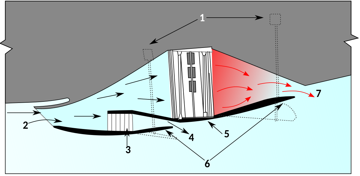
The idea is to use waste heat from the radiator in a piston engine to add heat to air compressed by ram effect in suitably shaped duct to increase engine efficiency.
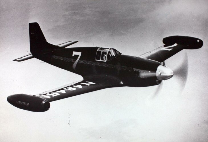
The following two NACA reports (both translations from German publications) might also be of interest:

- NACA-TM-893, "Contribution to the Theory of the Heated Duct Radiator" by H. Winter
- NACA-TM-896, "The Drag of Airplane Radiators with Special Reference to Air Heating (Comparison of Theory and Experiment)" by B. Göthert

For the sake of completeness, here also a link to the Meredith publication provided by Wikipedia:

- https://reports.aerade.cranfield.ac.uk/bitstream/handle/1826.2/1425/arc-rm-1683.pdf

Regards,

Henning (HoHun)
 
Beguine allegedly had input from North American engineers. Sticking the rads on the tips like that allows for a pretty much ideal duct, along with a gain in effective span and better aileron response. They didn't know about area ruling then so they wouldn't have been concerned about it - and I have doubts that it made a huge difference anyway.

That planes crash also nearly killed air racing in the US.
 
Radiators interest me----I wonder if they may additional roles....

I saw this piece of art at Reddit recently:
View: https://www.reddit.com/r/Damnthatsinteresting/comments/x8klyf/automatic_transmissions_are_analog_computers/


It reminded me of the clockwork parts of the F-1
The original F-1 was built somewhat like a wind-up clock: as one part of the startup sequence occurred it would mechanically or in some other way trigger the next part of the startup sequence and so on. Those who have looked at it today marvel at how clever it is.

Yet perhaps "obsolete" tech could re-appear?
Now a team of scientists from the Max Planck Institute for Intelligent Systems, the Technische Universität Dresden, the Friedrich-Alexander-Universität Erlangen-Nürnberg, and Oak Ridge National Laboratory has demonstrated that hydrogen condenses on a surface at a very low temperature near the H2 boiling point, forming a super-dense monolayer exceeding the density of liquid hydrogen by a factor of almost three, which reduces the volume to only 5 liters per kilogram H2.

So just maybe---LH2 tanks might look like the old automatic transmissions?

That would ruin the idea of wet workshops---but could radiators also be a type of tankage now? Serve one purpose as fuel tanks--serve another as just plain radiators later? We see some talk about getting hydrogen from ammonia on the fly----the waste nitrogen could back fill the radiators once a craft is up to speed and coasting perhaps?


The old tech of those beautiful automatic transmissions of yesteryear may yet serve a purpose....
 
If you enjoy hydro mechanical computers, you would love jet engine fuel controls from before the advent of electronic FADEC controls. The ultimate was the P&W F100-100/200 Unified Fuel Control manufactured by Bendix. There where cams, levers, servos, solenoids, feedback circuits, pressure and temperature measuring devices that controlled the starting of the engine, fuel flow from Idle to Mil power, variable vane angle, augmentor ignition and zone sequencing, and nozzle position, all in a box about 24 x 24 x 8”. It was said there were as many individual parts inside the UFC as there were in the rest of the engine. It was a marvel of engineering and worked pretty well, although it was completely outclassed when the Digital Electronic Engine Control replaced it on the F100-220 engine in the mid 1980s.

Sorry for the diversion. Now back to the topic…. Augmented Radiators
 
Last edited:
The link here between mechanical computers and cold storage is arbitrary and coincidental. The most complex mechanical computer ever built is Charles Babbage's analytical engine, the world's first general-purpose stored-program computer. Although he never finished its construction, Ada Lovelace wrote programs for it and the Science Museum has built a full-size working replica of the core mechanisms. Another remarkable computer, this one analogue, is the Antikythera mechanism, an ancient Greek orrery (geared model of the solar system) used to foretell auspicious alignments for the Olympic games (and no doubt the technology which inspired the Ptolemaic Universe). No cooling involved, and no hydrogen fluid, just inspiring applications of a wide-ranging technology.

Storing hydrogen in radiators? Reaction Engine's microtube heat exchangers spring immediately to mind. "polywater" is a similar semi-structured fluid inside very fine capillary tubes, about which similar "can we scale this out?" speculations have been thrown around. But the volume of material that you need to manufacture all those tubes, compared to the volume of fluid which can be stored in that initial monolayer, is far too clunky for a viable storage system as such. And if you just make things bigger the semi-fluid layer is not scalable. Increasing the number of tubes and shrinking their scale, analogous to a microchip, improves the surface-to-volume ratio, but you then run into problems getting the hydrogen in and out; either the tube and fluid materials repel and you can't get the stuff in, or they attract and you can't get it out again. Liquid crystal displays and lubricating oils offer examples which work with similar issues while sandwiched between surfaces rather than inside tubes.
There is one hydrogen concentration technology which does work, up to a point. You take a "micro-sponge" material such as lithium wire "wool" or a suitable clathrate, which provide the extreme surface-to-volume ratios you need. You then force hydrogen gas in under pressure. The hydrogen clings to the sponge and is greatly compressed compared to the gas, but is not as dense as when liquid. No expensive cryo cooling needed, and because the material is more a sponge than a tube, you can get the hydrogen gas in and out easily. It is also safer than bulk storage; back in the 1970s a guy developed a hydrogen fuelled car with lithium-hydride fuel storage. He could -and did - fire a rifle bullet through the fuel tank, and all that came out was a thin jet of hydrogen, no more hazardous than a gasoline leak. But again, no heat exchangers involved.
In none of these thin-film/concentration phenomena are computational mechanisms employed.
 
3D printing allows for perhaps smaller versions of these technologies. A nano ceramic printed difference engine could orbit a magnetar, say— and not be fried….

Analog mechanical computers may yet have a role. Fluidics might allow computation and fuel both at once?
 
Interesting topic, but please be aware of not drifting to far from the original topic ! ;)
 
According to a wartime article in SAE Journal, a cooling fan gives a substantial performance improvement in aircraft with air-cooled radials. The article was written by a Wright engineer.
 
It’s quite off topic, but if hydrogen is stored in Lithium hydrid, a lot of thermal energy with high temperature will be needed to set it free. The waste heat of PEM fuel cells is too cold for that purpose, that’s why this isn’t an option for fuel cell vehicles. Mercedes builded a van in the 70th with three different metal hydride tanks which released hydrogen at different temperatures. When the power output was high enough, the exhaust heat was used for the Lithium hydride storage and at lower loads other (forgot what is was) hydrides were being used which could release hydrogen at lower temperatures, but had a lower weight specific hydrogen content.

Going back to the radiators, the early BV155 prototypes didn’t have wing tip radiators, but also wing pods for the wing radiators. I guess this was done for two reasons, a better weight distribution which reduced the stress on the wing roots and a free cooling exhaust stream which wasn’t attached to the fuselage. I believe, in chin coolers, the warm cooling air with higher relative velocity to the fuselage than the surrounding air will cause increased friction. Later on, the weight penalty with all the plumping was the reason, why the last prototype of the BV155 had a more conventional chin cooler (I read it somewhere, but I forgot where I found it….).
 

Similar threads

Back
Top Bottom