
- Joined
- 16 December 2010
- Messages
- 2,832
- Reaction score
- 2,055
A two stage program to test the linear aerospike concept, the first test bed proved the basic concept, the second test bed explored the use of thrust vectoring.
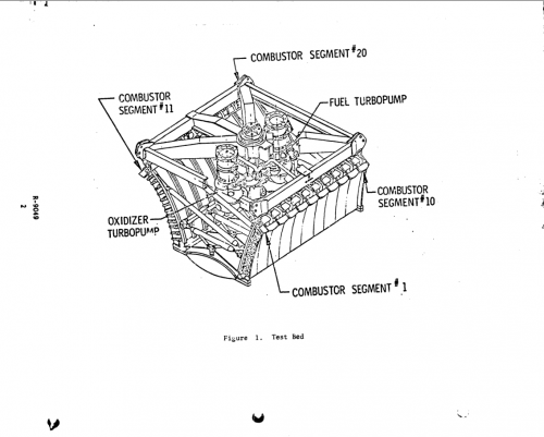
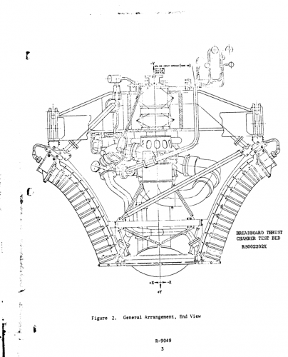
Linear test bed. Volume 1: Test bed no. 1. (Aerospike test bed with segmented combustor)
http://ntrs.nasa.gov/archive/nasa/casi.ntrs.nasa.gov/19740011779.pdf
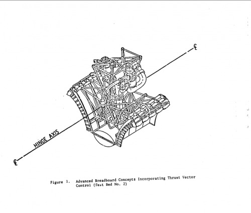
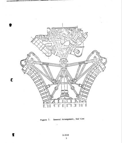
Linear Test Bed. Volume 2: Test Bed No. 2. (Linear aerospike test bed for thrust vector control)
http://ntrs.nasa.gov/archive/nasa/casi.ntrs.nasa.gov/19740011780.pdf
An 18 minute documentary on the program, which concludes with footage of the engines in operation. On YouTube some of this footage can be seen labeled as footage of the XRS-2200 designed for the X-33 project.
Linear test bed. Volume 1: Test bed no. 1. (Aerospike test bed with segmented combustor)
The Linear Test Bed program was to design, fabricate, and evaluation test an advanced aerospike test bed which employed the segmented combustor concept. The system is designated as a linear aerospike system and consists of a thrust chamber assembly, a power package, and a thrust frame. It was designed as an experimental system to demonstrate the feasibility of the linear aerospike-segmented combustor concept. The overall dimensions are 120 inches long by 120 inches wide by 96 inches in height. The propellants are liquid oxygen/liquid hydrogen. The system was designed to operate at 1200-psia chamber pressure, at a mixture ratio of 5.5. At the design conditions, the sea level thrust is 200,000 pounds.
http://ntrs.nasa.gov/archive/nasa/casi.ntrs.nasa.gov/19740011779.pdf
Linear Test Bed. Volume 2: Test Bed No. 2. (Linear aerospike test bed for thrust vector control)
Test bed No. 2 consists of 10 combustors welded in banks of 5 to 2 symmetrical tubular nozzle assemblies, an upper stationary thrust frame, a lower thrust frame which can be hinged, a power package, a triaxial combustion wave ignition system, a pneumatic control system, pneumatically actuated propellant valves, a purge and drain system, and an electrical control system. The power package consists of the Mark 29-F fuel turbopump, the Mark 29-0 oxidizer turbopump, a gas generator assembly, and propellant ducting. The system, designated as a linear aerospike system, was designed to demonstrate the feasibility of the concept and to explore technology related to thrust vector control, thrust vector optimization, improved sequencing and control, and advanced ignition systems. The propellants are liquid oxygen/liquid hydrogen. The system was designed to operate at 1200-psia chamber pressure at an engine mixture ratio of 5.5. With 10 combustors, the sea level thrust is 95,000 pounds.
http://ntrs.nasa.gov/archive/nasa/casi.ntrs.nasa.gov/19740011780.pdf
An 18 minute documentary on the program, which concludes with footage of the engines in operation. On YouTube some of this footage can be seen labeled as footage of the XRS-2200 designed for the X-33 project.
Attachments
Last edited: