
You are using an out of date browser. It may not display this or other websites correctly.
You should upgrade or use an alternative browser.
You should upgrade or use an alternative browser.
Heinkel Lerche/Wespe
- Thread starter hesham
- Start date
Maveric
Fight for yor Right!
- Joined
- 14 January 2007
- Messages
- 2,231
- Reaction score
- 854
hesham said:Also,
the Heinkel Lerche was called He.355A.
Never heared before. Yoursource hesham...?

- Joined
- 11 March 2006
- Messages
- 8,625
- Reaction score
- 3,806
That was my question , too, in the Fw thread. Those designations, without additional letters, look
like RLM designations. The Lerche and the Triebflügel actually may have been chosen as contenders
and got those numbers, but still yet I haven't found a list mentioning them.
like RLM designations. The Lerche and the Triebflügel actually may have been chosen as contenders
and got those numbers, but still yet I haven't found a list mentioning them.
Hi newsdeskdan,
you wrote "Furthermore, there is strong circumstantial evidence that Lerche II and Wespe were Daimler-Benz projects, not Heinkel."
In another thread I tried to question about this, but I got no answer. Can you please develop on this?
you wrote "Furthermore, there is strong circumstantial evidence that Lerche II and Wespe were Daimler-Benz projects, not Heinkel."
In another thread I tried to question about this, but I got no answer. Can you please develop on this?
- Joined
- 26 May 2006
- Messages
- 34,901
- Reaction score
- 15,775
- Joined
- 25 June 2009
- Messages
- 14,753
- Reaction score
- 6,151
A couple of suggestions:
1°) Could Reiniger's name on the plans refer to ANOTHER Reiniger fellow?
2°) Could it simply indicate these plans were his personal copies?
Besides, I strongly suggest this topic be subtly renamed as « The dubious Messerschmitt "P.1116" », or something of the kind.
1°) Could Reiniger's name on the plans refer to ANOTHER Reiniger fellow?
2°) Could it simply indicate these plans were his personal copies?
Besides, I strongly suggest this topic be subtly renamed as « The dubious Messerschmitt "P.1116" », or something of the kind.
- Joined
- 27 December 2005
- Messages
- 17,748
- Reaction score
- 26,421
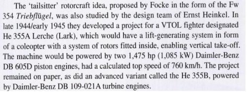
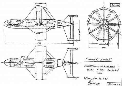
So - here's something more concrete - from Aeronautical Research in Germany: From Lilienthal until Today. Unfortunately P.372 was not part of the preview from Google books but P.373 reproduces a Lerche drawing.
Proposals to increase speed by using a propeller-jacket ring as Hydrofoil taking advantage of vertical takeoffs.
Heinkel Report, Vienna, 8 March 1945
Karl Reiniger is the author of the report. Its a contemporary, primary source. I'm pretty sure this is the original source for Coates, et al.
Proposals to increase speed by using a propeller-jacket ring as Hydrofoil taking advantage of vertical takeoffs.
Heinkel Report, Vienna, 8 March 1945
Karl Reiniger is the author of the report. Its a contemporary, primary source. I'm pretty sure this is the original source for Coates, et al.
Attachments
- Joined
- 27 December 2005
- Messages
- 17,748
- Reaction score
- 26,421
http://www.abebooks.de/servlet/BookDetailsPL?bi=16026632815
This book *might* be relevant (its a fairly comprehensive study of German STOL/VTOL aircraft from 1984).
This book *might* be relevant (its a fairly comprehensive study of German STOL/VTOL aircraft from 1984).
Attachments
- Joined
- 11 March 2006
- Messages
- 8,625
- Reaction score
- 3,806
Basil said:I wonder if Convair had knowledge of the Lerche / Wespe concept when they conceived the Model 49.
I would rather think of the BTZ designs, which are nearer to the Model 49, I think.
http://www.secretprojects.co.uk/forum/index.php/topic,6662.msg102910.html#msg102910
blackkite
Don't laugh, don't cry, don't even curse, but.....
- Joined
- 31 May 2007
- Messages
- 8,819
- Reaction score
- 7,716

blackkite
Don't laugh, don't cry, don't even curse, but.....
- Joined
- 31 May 2007
- Messages
- 8,819
- Reaction score
- 7,716
W
Wingknut
Guest
Hi folks,
One U.S. tail-sitter patent I found interesting is this one here from 1941:
http://www.secretprojects.co.uk/forum/index.php/topic,26764.0.html
Just an amateur’s idle curiosity this but what do you think about the feasibility of the Lerche II as a point-defence VTOL fighter? Advantages might include: tried power-plants grouped near the c. of g., twin-prop piston-engined reliability, annular wing to shroud props, prone-pilot lay-out for good(-ish) view, twin cannon etc. However, downsides might include e.g. narrow wheel-base, large frontal area, exposed pilot, etc. Still, maybe better than e.g. the Wespe or the Supermarine 4040 in several respects?
Any thoughts?
Cheers, ‘Wingknut’.
W
Wingknut
Guest
Hi folks,
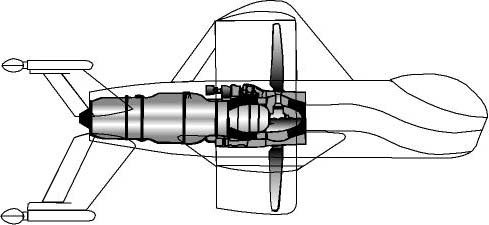
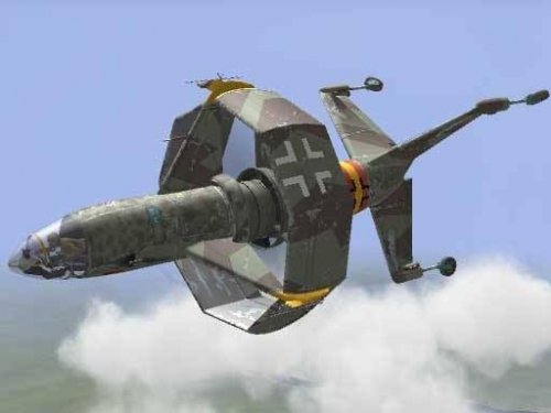
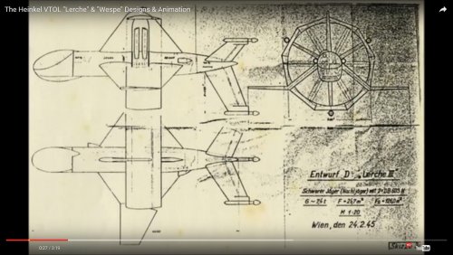
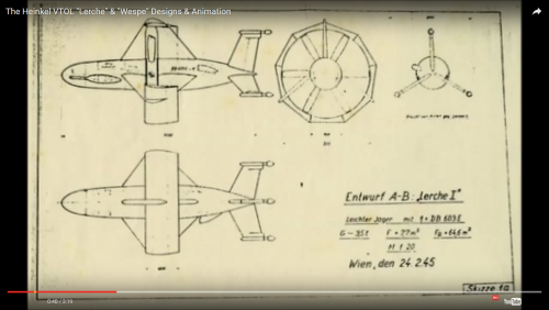
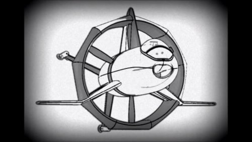
Following on from the very interesting YouTube video that Blackkite kindly shared with us, I took the liberty of downloading a couple of snapshots of different stages in Lerche II design from it, as below. I stress the file-names are mine so apologies if I've mislabelled.
Thanks, 'Wingknut'.
Following on from the very interesting YouTube video that Blackkite kindly shared with us, I took the liberty of downloading a couple of snapshots of different stages in Lerche II design from it, as below. I stress the file-names are mine so apologies if I've mislabelled.
Thanks, 'Wingknut'.
Attachments
- Joined
- 1 May 2007
- Messages
- 2,595
- Reaction score
- 1,965
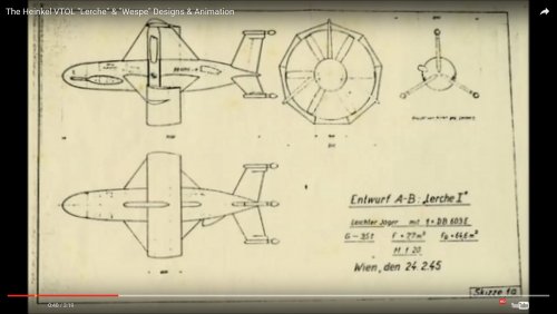
Wingknut, I believe you have indeed, mislabelled your screencaps.
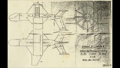
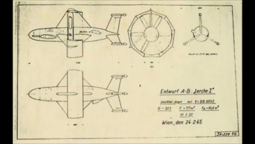
The one you have labelled 'Mid-Version' is clearly captioned 'Lerche II' and 'Entwurf A,B', and your 'Early Version', 'Lerche I' and 'Entwurf D'.
cheers,
Robin.
The one you have labelled 'Mid-Version' is clearly captioned 'Lerche II' and 'Entwurf A,B', and your 'Early Version', 'Lerche I' and 'Entwurf D'.
cheers,
Robin.
W
Wingknut
Guest
Thanks, Robin. I might still (tentatively) wonder though. It could just be I made a careless assumption but as far as I know, 'Lerche' evolution took it away from versions like that labelled 'D' and more towards ones like those labelled 'A', 'B' and 'C'. I’m not sure how much weight to give to the labels 'Lerche I', 'Lerche II', 'Lerche III' or A. B, C etc. to be honest. Still, with my meagre resources I really can't tell and I bet it's my bad ...
Thanks again and all best, 'Wingknut'.
Thanks again and all best, 'Wingknut'.
W
Wingknut
Guest
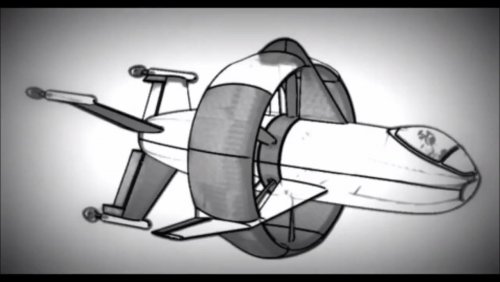
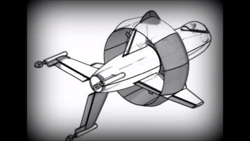
Just in an effort to atone for my apparent mislabelling a few posts ago, here are larger and (I hope) less-confusingly labelled screen-shots of the Lerche Entwurf A-B and Entwurf D. (Looking at the latter blown-up a bit, it seems to be the 'Lerche III', which just reinforces the idea that it's later than the others ...) Thanks again to Robin.
Attachments
W
Wingknut
Guest
Sorry, just realised that I saved (and uploaded) some of the above screenshots as rather large png files so here instead are the same images (and a couple more screenshots from the video above) rendered as somewhat smaller jpgs. I've tried to keep the file-names very simple this time. Thanks and all best, 'Wingknut'.
Attachments
-
 Wespe (Snapshot 4).jpg123.2 KB · Views: 212
 -
 Wespe (Snapshot 3).jpg135 KB · Views: 198
 -
 Wespe (Snapshot 2).jpg59.7 KB · Views: 181
 -
 Wespe (Snapshot 1).jpg110.3 KB · Views: 199
 -
 Lerche (Engine - Installation).jpg148 KB · Views: 204
 -
 Lerche (Head-On).jpg82.1 KB · Views: 249
 -
 Lerche Entwurf D.jpg299.6 KB · Views: 258
 -
 Lerche Entwurf A-B.jpg181.7 KB · Views: 296
- Joined
- 26 May 2006
- Messages
- 34,901
- Reaction score
- 15,775
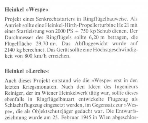
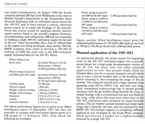
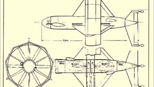
Also from Flieger Revue Extra 90,
Brought in the spring of 1945
Heinkel still have suggestions for
vertical take off interceptors
with jacketed propellers
out. The wasp should be from
a turboprop engine
Heinkel HeS 021 powered
become.
The drawing of the wasp in the
Flight and the three-sided rift
the machine (below) was
after the end of the war for the
Soviet victorious power
prepared.
Ivan Culjak
ACCESS: Confidential
- Joined
- 11 September 2021
- Messages
- 53
- Reaction score
- 53
You can be absolutely positive about it......Everything coming from Germany about aeronautics was thoroughly investigated from 1945 onward..Interesting thread.
I wonder if Convair had knowledge of the Lerche / Wespe concept when they conceived the Model 49.
Yes. However, sometimes concepts were also "re-invented", like the area rule.You can be absolutely positive about it......Everything coming from Germany about aeronautics was thoroughly investigated from 1945 onward..Interesting thread.
I wonder if Convair had knowledge of the Lerche / Wespe concept when they conceived the Model 49.
HereAs a more general question: has anyone test-flow a ring-wing Coeleptere powered by large diameter fan(s)?
https://en.wikipedia.org/wiki/Doak_VZ-4
https://en.wikipedia.org/wiki/Nord_Aviation_N_500_Cadet
https://en.wikipedia.org/wiki/Bell_X-22
Ivan Culjak
ACCESS: Confidential
- Joined
- 11 September 2021
- Messages
- 53
- Reaction score
- 53
Heinkel Wespe/Lerche - could/would it fly?
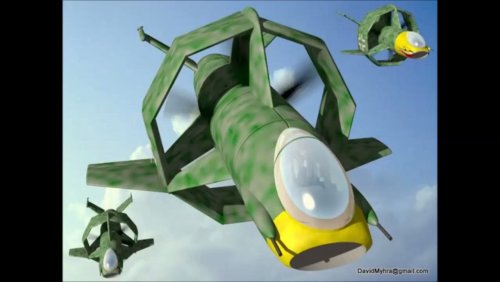
It seems that the Heinkel project Wespe/ Lerche looked very interesting to many - an aircraft that goes up vertically and flies fast – like a bird. For some (including me) it was very promising and it should have been working because a concept (ducted fan, annular wing) went through a proper development phase – with a lot of theoretical and research work done before (bio mimicking) ; for others it was oddity, wasting of time and money. The latter had better arguments – it did not fly.
So, if the idea was so good why has it never ever been used since then? OK, tail sitters were tried in the 50s (like Lockheed xfv, Pogo or Coleopter,...), but it wasn’t exactly the Lerche concept. And many ideas in aviation - no matter how good they were, never came to the point of being built – most often, if there is no urgent need for something new, everything is done with existing technology.
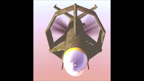
But, in the case of Lerche, something did happen – the coming of UAVs! Suddenly, there was no need for the pilot to be disoriented with tail sitting during takeoff and landing while the need for vertical take-off remains as very important for unmanned vehicles. So, if the Lerche concept was sound, it should be used with UAVs. And it has been so!
Here it is, a Martin V-bat UAV, a current favorite for US Army and US Navy tactical UAV - https://shield.ai/ ; V-bat, a ducted fan, tail sitting aircraft - conceptually, a Heinkel Lerche with addition of classic wings .

It wasn't said directly that it was Lerche inspired , but, for example, Professor Ron Barret from Kansas University, probably one of the most talented aerospace engineers, proposed the revolutionary XQ-138 drone family where he explicitly cited Heinkel Wespe (page 8.), US Pat. 6,502,787
https://ndiastorage.blob.core.usgovcloudapi.net/ndia/2012/armaments/Wednesday13655barrett.pdf
It seems that the Heinkel project Wespe/ Lerche looked very interesting to many - an aircraft that goes up vertically and flies fast – like a bird. For some (including me) it was very promising and it should have been working because a concept (ducted fan, annular wing) went through a proper development phase – with a lot of theoretical and research work done before (bio mimicking) ; for others it was oddity, wasting of time and money. The latter had better arguments – it did not fly.
So, if the idea was so good why has it never ever been used since then? OK, tail sitters were tried in the 50s (like Lockheed xfv, Pogo or Coleopter,...), but it wasn’t exactly the Lerche concept. And many ideas in aviation - no matter how good they were, never came to the point of being built – most often, if there is no urgent need for something new, everything is done with existing technology.
But, in the case of Lerche, something did happen – the coming of UAVs! Suddenly, there was no need for the pilot to be disoriented with tail sitting during takeoff and landing while the need for vertical take-off remains as very important for unmanned vehicles. So, if the Lerche concept was sound, it should be used with UAVs. And it has been so!
Here it is, a Martin V-bat UAV, a current favorite for US Army and US Navy tactical UAV - https://shield.ai/ ; V-bat, a ducted fan, tail sitting aircraft - conceptually, a Heinkel Lerche with addition of classic wings .

It wasn't said directly that it was Lerche inspired , but, for example, Professor Ron Barret from Kansas University, probably one of the most talented aerospace engineers, proposed the revolutionary XQ-138 drone family where he explicitly cited Heinkel Wespe (page 8.), US Pat. 6,502,787
https://ndiastorage.blob.core.usgovcloudapi.net/ndia/2012/armaments/Wednesday13655barrett.pdf
BigMacDaddy
ACCESS: Restricted
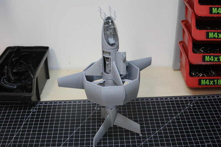
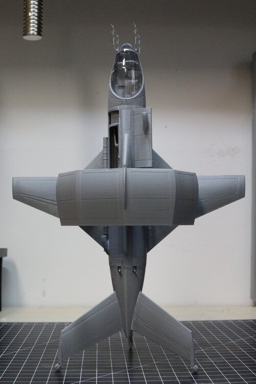
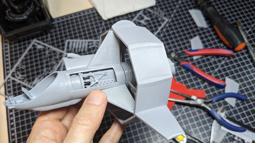
I cannot comment on the viability of this as a plane / RC vehicle / fan propelled but the basic aerodynamics more-or-less work as a model rocket. I think I originally found out about this model from these forums so thought I would share my Model Rocket build here.
Here is the launch it was windy so it may have windcocked and/or this preferred to fly like a plane a bit more than a model rocket):
View: https://www.youtube.com/shorts/FiO9EOdxT-w


Here is the launch it was windy so it may have windcocked and/or this preferred to fly like a plane a bit more than a model rocket):


In January 1944 Daimler Benz built a twenty-four cylinders engine with 3,800 hp, called DB 613, formed by two DB 603 G engines coupled together to drive a single-shaft power with contra-rotating airscrews. But the set weighed two tons and was not useful to propel a VTOL aircraft.
In the last days of the World War Two, high power and reasonable weight was just a dream, piston engines weighed too much and jet engines had very little thrust.
Lacking engines with sufficient power, Heinkel’s designers attempted to increase the efficiency by using ducted propellers, based on those of the Italian experimental aircraft Caproni Stipa, and annular wings based on the aerodynamic theories of Dipl.-Ing. Helmut Graf von Zborowski.
Inside an annular wing the tapered duct compressed the propeller’s airflow applying Benoulli’s principle. As the air forced into Venturi duct it accelerates.
Annular wings with ducted propellers were advantageous in augmenting engine thrust and in providing additional lifting area in forward flight. This means that a larger propeller with a greater pitch not require more engine power.
By incorporating adjustable control surfaces and varying the cross-section, the duct increases thrust efficiency by up 90 per cent in comparison to a similar-sized propeller in free-air.
It must be made rigid enough not to distort under flight, combat and landing loads.
A VTOL fighter needed that engine power to be delivered with rapid response even at the highest power levels.
The thrust needed to get off the ground had to exceed aircraft weight, but it was necessary for the power plant to provide additional thrust for maneuvering vertically.
A typical value for total thrust needed for vertical acceleration and maneuvering in the other axes would be about 1.7 times the aircraft maximum weight, on the contrary the thrust required in cruising flight would be only a fifth of aircraft weight.
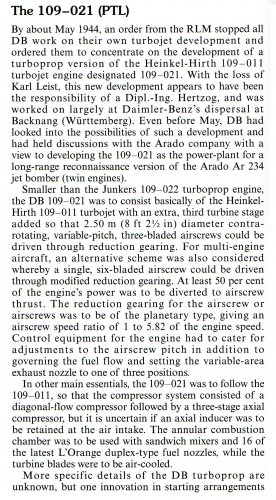
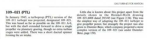
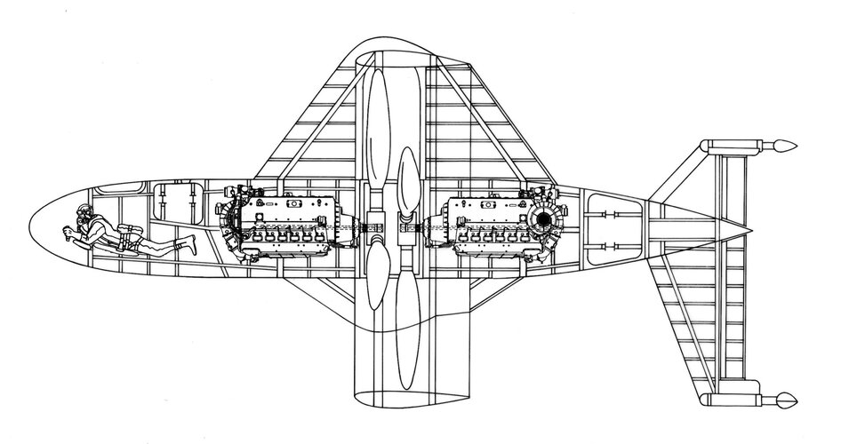
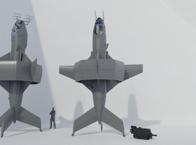
In December 1944, Dr.-Ing. Gerhard Schulze and Dipl.-Ing. Kurt Reiniger fron Heinkel-Wiener Neustädter Flugzeugwerke, designed two tilsitter fighters with annular wing called Heinkel He 355A Lerche and Heinkel He 355 B Wespe.
In February 1945, the VTOL project Lerche was proposed to the RLM in three different versions: Leuchter Jäger Lerche I (24.2.45), Schlachtflugzeug Lerche II (25.2.45) and Schwerer Jäger Lerche III (24.2.45).
Lerche I was a light fighter that weighed half as much as a Focke-Wulf Ta 152 C-3, it was powered by one Daimler-Benz DB 603 E and a six-blades ducted propeller with automatic-pitch control. This powerful engine generated a great deal of torque, to compensate this effect deflector vanes were mounted in the duct airstream.
Transition from over to forward flight was initiated by tilting the nose forward and gathering horizontal speed until wing lift took over.
There was a change in trim as the aircraft was rotated but control could be exercised by moving the vanes.
A sophisticated surface-cooling system developed for the high performance interceptor Heinkel project P. 1076, was integrated in the annular wing. The section between the spars housed the condensation tanks, the heat exchangers and the electric-driven pumps.
To avoid turbulence in the air stream produced by a protruding cockpit hood, it was necessary to design a fuselage of circular section based on that of the P. 1077 Julia project, with the pilot lying in prone position.
The automatic landing system was designed by Dipl.-Ing. Walter Hohbach.
In flight the three landing gear wheels were covered to save drag.
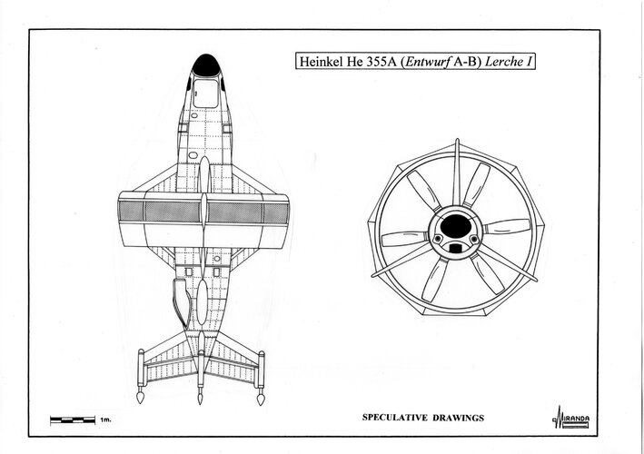
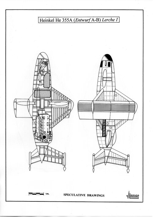
Heinkel He 355A (Entwurf A-B) Lerche I technical data
Ring wing diameter: 3.8 m, overall length: 7.75 m, rotor diameter: 3.3 m, wing area: 27 sq. m, surface area: 64.6 sq. m, wing chord: 2.79 m, estimated max weight: 2,500 kg, power plant: one DB 603E, twelve cylinder, inverted-Vee, liquid cooled engine with two-stage TKL 15 turbo-supercharger, rated at 1,810 hp in cruising flight and 2,250 hp at take-off with MW 50 booster, armament: two Mk 108/30 cannons mounted on each side of the fuselage with 3.5 degrees slope, electronics: EZ 42 gyroscopic gunsight, FuG 16 ZY R/T, FuG 25a IFF, FuG 125a radio-beacon, FuG radio-altimeter and Patin PKS auto-pilot.
In the last days of the World War Two, high power and reasonable weight was just a dream, piston engines weighed too much and jet engines had very little thrust.
Lacking engines with sufficient power, Heinkel’s designers attempted to increase the efficiency by using ducted propellers, based on those of the Italian experimental aircraft Caproni Stipa, and annular wings based on the aerodynamic theories of Dipl.-Ing. Helmut Graf von Zborowski.
Inside an annular wing the tapered duct compressed the propeller’s airflow applying Benoulli’s principle. As the air forced into Venturi duct it accelerates.
Annular wings with ducted propellers were advantageous in augmenting engine thrust and in providing additional lifting area in forward flight. This means that a larger propeller with a greater pitch not require more engine power.
By incorporating adjustable control surfaces and varying the cross-section, the duct increases thrust efficiency by up 90 per cent in comparison to a similar-sized propeller in free-air.
It must be made rigid enough not to distort under flight, combat and landing loads.
A VTOL fighter needed that engine power to be delivered with rapid response even at the highest power levels.
The thrust needed to get off the ground had to exceed aircraft weight, but it was necessary for the power plant to provide additional thrust for maneuvering vertically.
A typical value for total thrust needed for vertical acceleration and maneuvering in the other axes would be about 1.7 times the aircraft maximum weight, on the contrary the thrust required in cruising flight would be only a fifth of aircraft weight.
In December 1944, Dr.-Ing. Gerhard Schulze and Dipl.-Ing. Kurt Reiniger fron Heinkel-Wiener Neustädter Flugzeugwerke, designed two tilsitter fighters with annular wing called Heinkel He 355A Lerche and Heinkel He 355 B Wespe.
In February 1945, the VTOL project Lerche was proposed to the RLM in three different versions: Leuchter Jäger Lerche I (24.2.45), Schlachtflugzeug Lerche II (25.2.45) and Schwerer Jäger Lerche III (24.2.45).
Lerche I was a light fighter that weighed half as much as a Focke-Wulf Ta 152 C-3, it was powered by one Daimler-Benz DB 603 E and a six-blades ducted propeller with automatic-pitch control. This powerful engine generated a great deal of torque, to compensate this effect deflector vanes were mounted in the duct airstream.
Transition from over to forward flight was initiated by tilting the nose forward and gathering horizontal speed until wing lift took over.
There was a change in trim as the aircraft was rotated but control could be exercised by moving the vanes.
A sophisticated surface-cooling system developed for the high performance interceptor Heinkel project P. 1076, was integrated in the annular wing. The section between the spars housed the condensation tanks, the heat exchangers and the electric-driven pumps.
To avoid turbulence in the air stream produced by a protruding cockpit hood, it was necessary to design a fuselage of circular section based on that of the P. 1077 Julia project, with the pilot lying in prone position.
The automatic landing system was designed by Dipl.-Ing. Walter Hohbach.
In flight the three landing gear wheels were covered to save drag.
Heinkel He 355A (Entwurf A-B) Lerche I technical data
Ring wing diameter: 3.8 m, overall length: 7.75 m, rotor diameter: 3.3 m, wing area: 27 sq. m, surface area: 64.6 sq. m, wing chord: 2.79 m, estimated max weight: 2,500 kg, power plant: one DB 603E, twelve cylinder, inverted-Vee, liquid cooled engine with two-stage TKL 15 turbo-supercharger, rated at 1,810 hp in cruising flight and 2,250 hp at take-off with MW 50 booster, armament: two Mk 108/30 cannons mounted on each side of the fuselage with 3.5 degrees slope, electronics: EZ 42 gyroscopic gunsight, FuG 16 ZY R/T, FuG 25a IFF, FuG 125a radio-beacon, FuG radio-altimeter and Patin PKS auto-pilot.
Attachments
No
athpilot
Fly me to the moon...
- Joined
- 18 November 2012
- Messages
- 412
- Reaction score
- 453
Dear Justo, great thanks for sharing! Please more on the Lerche / Wespe.In January 1944 Daimler Benz built a twenty-four cylinders engine with 3,800 hp, called DB 613, formed by two DB 603 G engines coupled together to drive a single-shaft power with contra-rotating airscrews. But the set weighed two tons and was not useful to propel a VTOL aircraft.
In the last days of the World War Two, high power and reasonable weight was just a dream, piston engines weighed too much and jet engines had very little thrust.
Lacking engines with sufficient power, Heinkel’s designers attempted to increase the efficiency by using ducted propellers, based on those of the Italian experimental aircraft Caproni Stipa, and annular wings based on the aerodynamic theories of Dipl.-Ing. Helmut Graf von Zborowski.
Inside an annular wing the tapered duct compressed the propeller’s airflow applying Benoulli’s principle. As the air forced into Venturi duct it accelerates.
Annular wings with ducted propellers were advantageous in augmenting engine thrust and in providing additional lifting area in forward flight. This means that a larger propeller with a greater pitch not require more engine power.
By incorporating adjustable control surfaces and varying the cross-section, the duct increases thrust efficiency by up 90 per cent in comparison to a similar-sized propeller in free-air.
It must be made rigid enough not to distort under flight, combat and landing loads.
A VTOL fighter needed that engine power to be delivered with rapid response even at the highest power levels.
The thrust needed to get off the ground had to exceed aircraft weight, but it was necessary for the power plant to provide additional thrust for maneuvering vertically.
A typical value for total thrust needed for vertical acceleration and maneuvering in the other axes would be about 1.7 times the aircraft maximum weight, on the contrary the thrust required in cruising flight would be only a fifth of aircraft weight.
In December 1944, Dr.-Ing. Gerhard Schulze and Dipl.-Ing. Kurt Reiniger fron Heinkel-Wiener Neustädter Flugzeugwerke, designed two tilsitter fighters with annular wing called Heinkel He 355A Lerche and Heinkel He 355 B Wespe.
In February 1945, the VTOL project Lerche was proposed to the RLM in three different versions: Leuchter Jäger Lerche I (24.2.45), Schlachtflugzeug Lerche II (25.2.45) and Schwerer Jäger Lerche III (24.2.45).
Lerche I was a light fighter that weighed half as much as a Focke-Wulf Ta 152 C-3, it was powered by one Daimler-Benz DB 603 E and a six-blades ducted propeller with automatic-pitch control. This powerful engine generated a great deal of torque, to compensate this effect deflector vanes were mounted in the duct airstream.
Transition from over to forward flight was initiated by tilting the nose forward and gathering horizontal speed until wing lift took over.
There was a change in trim as the aircraft was rotated but control could be exercised by moving the vanes.
A sophisticated surface-cooling system developed for the high performance interceptor Heinkel project P. 1076, was integrated in the annular wing. The section between the spars housed the condensation tanks, the heat exchangers and the electric-driven pumps.
To avoid turbulence in the air stream produced by a protruding cockpit hood, it was necessary to design a fuselage of circular section based on that of the P. 1077 Julia project, with the pilot lying in prone position.
The automatic landing system was designed by Dipl.-Ing. Walter Hohbach.
In flight the three landing gear wheels were covered to save drag.
Heinkel He 355A (Entwurf A-B) Lerche I technical data
Ring wing diameter: 3.8 m, overall length: 7.75 m, rotor diameter: 3.3 m, wing area: 27 sq. m, surface area: 64.6 sq. m, wing chord: 2.79 m, estimated max weight: 2,500 kg, power plant: one DB 603E, twelve cylinder, inverted-Vee, liquid cooled engine with two-stage TKL 15 turbo-supercharger, rated at 1,810 hp in cruising flight and 2,250 hp at take-off with MW 50 booster, armament: two Mk 108/30 cannons mounted on each side of the fuselage with 3.5 degrees slope, electronics: EZ 42 gyroscopic gunsight, FuG 16 ZY R/T, FuG 25a IFF, FuG 125a radio-beacon, FuG radio-altimeter and Patin PKS auto-pilot.
On the benchDear Justo, great thanks for sharing! Please more on the Lerche / Wespe.In January 1944 Daimler Benz built a twenty-four cylinders engine with 3,800 hp, called DB 613, formed by two DB 603 G engines coupled together to drive a single-shaft power with contra-rotating airscrews. But the set weighed two tons and was not useful to propel a VTOL aircraft.
In the last days of the World War Two, high power and reasonable weight was just a dream, piston engines weighed too much and jet engines had very little thrust.
Lacking engines with sufficient power, Heinkel’s designers attempted to increase the efficiency by using ducted propellers, based on those of the Italian experimental aircraft Caproni Stipa, and annular wings based on the aerodynamic theories of Dipl.-Ing. Helmut Graf von Zborowski.
Inside an annular wing the tapered duct compressed the propeller’s airflow applying Benoulli’s principle. As the air forced into Venturi duct it accelerates.
Annular wings with ducted propellers were advantageous in augmenting engine thrust and in providing additional lifting area in forward flight. This means that a larger propeller with a greater pitch not require more engine power.
By incorporating adjustable control surfaces and varying the cross-section, the duct increases thrust efficiency by up 90 per cent in comparison to a similar-sized propeller in free-air.
It must be made rigid enough not to distort under flight, combat and landing loads.
A VTOL fighter needed that engine power to be delivered with rapid response even at the highest power levels.
The thrust needed to get off the ground had to exceed aircraft weight, but it was necessary for the power plant to provide additional thrust for maneuvering vertically.
A typical value for total thrust needed for vertical acceleration and maneuvering in the other axes would be about 1.7 times the aircraft maximum weight, on the contrary the thrust required in cruising flight would be only a fifth of aircraft weight.
In December 1944, Dr.-Ing. Gerhard Schulze and Dipl.-Ing. Kurt Reiniger fron Heinkel-Wiener Neustädter Flugzeugwerke, designed two tilsitter fighters with annular wing called Heinkel He 355A Lerche and Heinkel He 355 B Wespe.
In February 1945, the VTOL project Lerche was proposed to the RLM in three different versions: Leuchter Jäger Lerche I (24.2.45), Schlachtflugzeug Lerche II (25.2.45) and Schwerer Jäger Lerche III (24.2.45).
Lerche I was a light fighter that weighed half as much as a Focke-Wulf Ta 152 C-3, it was powered by one Daimler-Benz DB 603 E and a six-blades ducted propeller with automatic-pitch control. This powerful engine generated a great deal of torque, to compensate this effect deflector vanes were mounted in the duct airstream.
Transition from over to forward flight was initiated by tilting the nose forward and gathering horizontal speed until wing lift took over.
There was a change in trim as the aircraft was rotated but control could be exercised by moving the vanes.
A sophisticated surface-cooling system developed for the high performance interceptor Heinkel project P. 1076, was integrated in the annular wing. The section between the spars housed the condensation tanks, the heat exchangers and the electric-driven pumps.
To avoid turbulence in the air stream produced by a protruding cockpit hood, it was necessary to design a fuselage of circular section based on that of the P. 1077 Julia project, with the pilot lying in prone position.
The automatic landing system was designed by Dipl.-Ing. Walter Hohbach.
In flight the three landing gear wheels were covered to save drag.
Heinkel He 355A (Entwurf A-B) Lerche I technical data
Ring wing diameter: 3.8 m, overall length: 7.75 m, rotor diameter: 3.3 m, wing area: 27 sq. m, surface area: 64.6 sq. m, wing chord: 2.79 m, estimated max weight: 2,500 kg, power plant: one DB 603E, twelve cylinder, inverted-Vee, liquid cooled engine with two-stage TKL 15 turbo-supercharger, rated at 1,810 hp in cruising flight and 2,250 hp at take-off with MW 50 booster, armament: two Mk 108/30 cannons mounted on each side of the fuselage with 3.5 degrees slope, electronics: EZ 42 gyroscopic gunsight, FuG 16 ZY R/T, FuG 25a IFF, FuG 125a radio-beacon, FuG radio-altimeter and Patin PKS auto-pilot.
Attachments
napobona
ACCESS: Restricted
On the benchDear Justo, great thanks for sharing! Please more on the Lerche / Wespe.In January 1944 Daimler Benz built a twenty-four cylinders engine with 3,800 hp, called DB 613, formed by two DB 603 G engines coupled together to drive a single-shaft power with contra-rotating airscrews. But the set weighed two tons and was not useful to propel a VTOL aircraft.
In the last days of the World War Two, high power and reasonable weight was just a dream, piston engines weighed too much and jet engines had very little thrust.
Lacking engines with sufficient power, Heinkel’s designers attempted to increase the efficiency by using ducted propellers, based on those of the Italian experimental aircraft Caproni Stipa, and annular wings based on the aerodynamic theories of Dipl.-Ing. Helmut Graf von Zborowski.
Inside an annular wing the tapered duct compressed the propeller’s airflow applying Benoulli’s principle. As the air forced into Venturi duct it accelerates.
Annular wings with ducted propellers were advantageous in augmenting engine thrust and in providing additional lifting area in forward flight. This means that a larger propeller with a greater pitch not require more engine power.
By incorporating adjustable control surfaces and varying the cross-section, the duct increases thrust efficiency by up 90 per cent in comparison to a similar-sized propeller in free-air.
It must be made rigid enough not to distort under flight, combat and landing loads.
A VTOL fighter needed that engine power to be delivered with rapid response even at the highest power levels.
The thrust needed to get off the ground had to exceed aircraft weight, but it was necessary for the power plant to provide additional thrust for maneuvering vertically.
A typical value for total thrust needed for vertical acceleration and maneuvering in the other axes would be about 1.7 times the aircraft maximum weight, on the contrary the thrust required in cruising flight would be only a fifth of aircraft weight.
In December 1944, Dr.-Ing. Gerhard Schulze and Dipl.-Ing. Kurt Reiniger fron Heinkel-Wiener Neustädter Flugzeugwerke, designed two tilsitter fighters with annular wing called Heinkel He 355A Lerche and Heinkel He 355 B Wespe.
In February 1945, the VTOL project Lerche was proposed to the RLM in three different versions: Leuchter Jäger Lerche I (24.2.45), Schlachtflugzeug Lerche II (25.2.45) and Schwerer Jäger Lerche III (24.2.45).
Lerche I was a light fighter that weighed half as much as a Focke-Wulf Ta 152 C-3, it was powered by one Daimler-Benz DB 603 E and a six-blades ducted propeller with automatic-pitch control. This powerful engine generated a great deal of torque, to compensate this effect deflector vanes were mounted in the duct airstream.
Transition from over to forward flight was initiated by tilting the nose forward and gathering horizontal speed until wing lift took over.
There was a change in trim as the aircraft was rotated but control could be exercised by moving the vanes.
A sophisticated surface-cooling system developed for the high performance interceptor Heinkel project P. 1076, was integrated in the annular wing. The section between the spars housed the condensation tanks, the heat exchangers and the electric-driven pumps.
To avoid turbulence in the air stream produced by a protruding cockpit hood, it was necessary to design a fuselage of circular section based on that of the P. 1077 Julia project, with the pilot lying in prone position.
The automatic landing system was designed by Dipl.-Ing. Walter Hohbach.
In flight the three landing gear wheels were covered to save drag.
Heinkel He 355A (Entwurf A-B) Lerche I technical data
Ring wing diameter: 3.8 m, overall length: 7.75 m, rotor diameter: 3.3 m, wing area: 27 sq. m, surface area: 64.6 sq. m, wing chord: 2.79 m, estimated max weight: 2,500 kg, power plant: one DB 603E, twelve cylinder, inverted-Vee, liquid cooled engine with two-stage TKL 15 turbo-supercharger, rated at 1,810 hp in cruising flight and 2,250 hp at take-off with MW 50 booster, armament: two Mk 108/30 cannons mounted on each side of the fuselage with 3.5 degrees slope, electronics: EZ 42 gyroscopic gunsight, FuG 16 ZY R/T, FuG 25a IFF, FuG 125a radio-beacon, FuG radio-altimeter and Patin PKS auto-pilot.
Attachments
- Joined
- 11 March 2012
- Messages
- 3,249
- Reaction score
- 3,179
Structural question: how do you keep those two propellers in correct alignment with such long load-paths … going from engine mounts all the way out to wing-tips … er … ring-tips … and back inboard to the second propeller?On the benchDear Justo, great thanks for sharing! Please more on the Lerche / Wespe.In January 1944 Daimler Benz built a twenty-four cylinders engine with 3,800 hp, called DB 613, formed by two DB 603 G engines coupled together to drive a single-shaft power with contra-rotating airscrews. But the set weighed two tons and was not useful to propel a VTOL aircraft.
In the last days of the World War Two, high power and reasonable weight was just a dream, piston engines weighed too much and jet engines had very little thrust.
Lacking engines with sufficient power, Heinkel’s designers attempted to increase the efficiency by using ducted propellers, based on those of the Italian experimental aircraft Caproni Stipa, and annular wings based on the aerodynamic theories of Dipl.-Ing. Helmut Graf von Zborowski.
Inside an annular wing the tapered duct compressed the propeller’s airflow applying Benoulli’s principle. As the air forced into Venturi duct it accelerates.
Annular wings with ducted propellers were advantageous in augmenting engine thrust and in providing additional lifting area in forward flight. This means that a larger propeller with a greater pitch not require more engine power.
By incorporating adjustable control surfaces and varying the cross-section, the duct increases thrust efficiency by up 90 per cent in comparison to a similar-sized propeller in free-air.
It must be made rigid enough not to distort under flight, combat and landing loads.
A VTOL fighter needed that engine power to be delivered with rapid response even at the highest power levels.
The thrust needed to get off the ground had to exceed aircraft weight, but it was necessary for the power plant to provide additional thrust for maneuvering vertically.
A typical value for total thrust needed for vertical acceleration and maneuvering in the other axes would be about 1.7 times the aircraft maximum weight, on the contrary the thrust required in cruising flight would be only a fifth of aircraft weight.
In December 1944, Dr.-Ing. Gerhard Schulze and Dipl.-Ing. Kurt Reiniger fron Heinkel-Wiener Neustädter Flugzeugwerke, designed two tilsitter fighters with annular wing called Heinkel He 355A Lerche and Heinkel He 355 B Wespe.
In February 1945, the VTOL project Lerche was proposed to the RLM in three different versions: Leuchter Jäger Lerche I (24.2.45), Schlachtflugzeug Lerche II (25.2.45) and Schwerer Jäger Lerche III (24.2.45).
Lerche I was a light fighter that weighed half as much as a Focke-Wulf Ta 152 C-3, it was powered by one Daimler-Benz DB 603 E and a six-blades ducted propeller with automatic-pitch control. This powerful engine generated a great deal of torque, to compensate this effect deflector vanes were mounted in the duct airstream.
Transition from over to forward flight was initiated by tilting the nose forward and gathering horizontal speed until wing lift took over.
There was a change in trim as the aircraft was rotated but control could be exercised by moving the vanes.
A sophisticated surface-cooling system developed for the high performance interceptor Heinkel project P. 1076, was integrated in the annular wing. The section between the spars housed the condensation tanks, the heat exchangers and the electric-driven pumps.
To avoid turbulence in the air stream produced by a protruding cockpit hood, it was necessary to design a fuselage of circular section based on that of the P. 1077 Julia project, with the pilot lying in prone position.
The automatic landing system was designed by Dipl.-Ing. Walter Hohbach.
In flight the three landing gear wheels were covered to save drag.
Heinkel He 355A (Entwurf A-B) Lerche I technical data
Ring wing diameter: 3.8 m, overall length: 7.75 m, rotor diameter: 3.3 m, wing area: 27 sq. m, surface area: 64.6 sq. m, wing chord: 2.79 m, estimated max weight: 2,500 kg, power plant: one DB 603E, twelve cylinder, inverted-Vee, liquid cooled engine with two-stage TKL 15 turbo-supercharger, rated at 1,810 hp in cruising flight and 2,250 hp at take-off with MW 50 booster, armament: two Mk 108/30 cannons mounted on each side of the fuselage with 3.5 degrees slope, electronics: EZ 42 gyroscopic gunsight, FuG 16 ZY R/T, FuG 25a IFF, FuG 125a radio-beacon, FuG radio-altimeter and Patin PKS auto-pilot.
How close can you mount two propellers - rotating on separate shafts - before they clash?
Similar threads
-
GERMAN CONCEPT PLANES VOLUME FIVE - VTOL 1933-1945
- Started by Justo Miranda
- Replies: 3
-

-
Potential new Osprey Publishing books in the X-Planes book series
- Started by Vahe Demirjian
- Replies: 3
-
 Heinkel Lerche III action artwork (Luftwaffe Secret Projects)
- Started by Skyraider3D
- Replies: 6
-
 Luftwaffe Test Pilot: flying captured allied aircraft of WW II
- Started by AeroFranz
- Replies: 3