Supermarine Racer Aircraft Developments (Projects)

hesham

ACCESS: USAP
Senior Member
Joined
26 May 2006
Messages
32,643
Reaction score
11,822
Hi,


from Aeroplane monthly,the Company Profile,here is the Supermarine S.4 as a high
speed variant which led to S.5,also the S.5 with strut-braced at wing,and finally the
S.6 as a biplane aircraft.
 

Attachments

  • S.4.png
    S.4.png
    126.3 KB · Views: 566
  • S.5.png
    S.5.png
    146.5 KB · Views: 541
  • S.6.png
    S.6.png
    153 KB · Views: 525
Originally published in the Putnam book Supermarine Aircraft since 1914, by Andrews and Morgan.
 
.....but incorrect. That is actually the original concept for the S4, not a high-speed development.
The biplane S6b is an oddity, described as a method to reduce landing speed, dated after the 1931 contest, and why would you want to?
 
The Merlin was at first designed to have a novel cooling system. Evaporative cooling was to be provided by condensers in the wings with a small retractable radiator for use at low speeds and when taxiing.
https://en.wikipedia.org/wiki/Rolls-Royce_Merlin

S6B
There were only seven months to prepare an entry, and as Mitchell did not have enough time to design a new aircraft, better performance had to be obtained by getting more power from the R-Type engine[5] Modifications to the airframe design were limited to minor improvements and some strengthening in order to cope with the increased weight of the aircraft. Additionally, the floats were extended forward by some three feet (0.9 m). Rolls-Royce had managed to increase the power of the engine by 400 hp (298 kW) to 2,300 hp (1,715 kW).
https://en.wikipedia.org/wiki/Supermarine_S.6B

Cooling
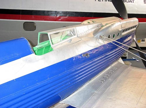
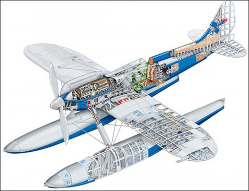
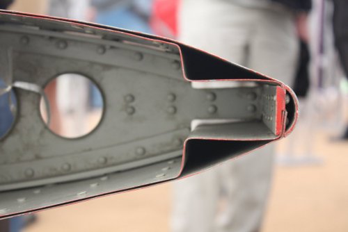
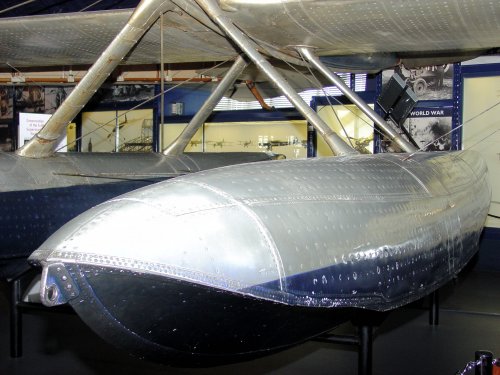
Cooling this large engine whilst minimising aerodynamic drag posed new challenges for both the Rolls-Royce and Supermarine design teams. Traditional cooling methods using honeycomb-type radiators were known to cause high drag in flight; consequently it was decided to use the surface skins of the S.6 wings and floats as heat exchangers, employing a double-skinned structure through which the coolant could circulate. Engine oil was cooled in a similar manner using channels in the fuselage and empennage skins. The S.6 was described at the time as a "flying radiator", and it had been estimated that this coolant system dissipated the equivalent of 1,000 hp (745 kW) of heat in flight. However, even with this system in use, engine overheating was noted during the race flights, requiring the pilots to reduce the throttle setting to maintain a safe operating temperature.
https://en.wikipedia.org/wiki/Rolls-Royce_R

So S6B's skin cooler(radiator and oil cooler) was not a evapolative cooler.
You can see engine cooling water flow channel under the wing and float skin in bottom picture.
Also you can see oil cooling tube at the side surface of the fuselage.
 

Attachments

  • 740x550.jpg
    740x550.jpg
    70.4 KB · Views: 297
  • PLAN.jpg
    PLAN.jpg
    167.1 KB · Views: 305
Rolls-Royce first experimented with evaporative cooling with the Kestrel, most notably flight tests in a modified Supermarine Southampton II, and seemed to be successful. The developed version became the Goshawk and it was planned to use it for the larger Buzzard engine too. However the positioning and type of radiator/condenser proved to be critical and for smaller agile aircraft, i.e. fighters, the problems proved to be insurmountable. Keeping water and steam separate, preventing re-boiling in the pumps and other issues led to the idea being dropped in 1935. R-R patented a number of condensing radiators and associated pumps and separators and Supermarine patented some forms of wing condenser.

The flat surface radiators fitted to the Supermarine-Napier S5 had proven very successful so the system was incorporated in the S6 but this time with them actually forming the flying surfaces rather than attached separately to the wing. Panels were tested in the RAE wind tunnel to assess their effectiveness and indicated that they may prove inadequate, so Mitchell fabricated additional radiators to be fitted to the floats if the predictions proved correct. He also added small scoops in the wing tips and vents in the roots to provide an airflow over the inner surface of the radiators, and these were also assessed in the wind tunnel. It is not generally known but when the wing surface radiators in the S6 proved to be inadequate to dissipate the heat from the 'R' engine in early flight tests they ran brief experiments using Ethylene Glycol as the coolant, but this created all kind of problems with the flexible connectors and joints in the system and R-R where not too happy to run the 'R' at higher temperatures, so the idea was dropped.
 
Thanks a lot. I understand that there are two types of skin cooler. Evaporative type and non evaporative type.
 
blackkite said:
Thanks a lot. I understand that there are two types of skin cooler. Evaporative type and non evaporative type.
That is correct but no Schneider racer ever employed evaporative cooling.
 
Oh today I realize so. Thanks a lot professor. B)
 
This is a section through the leading edge of the S6 wing. You can see the narrow spacing between the skins for the water and the span-wise corrugations that form the feeder channels
 

Attachments

  • S6b radiator.jpg
    S6b radiator.jpg
    80.6 KB · Views: 87
What a surprising detailed picture!! Thanks again. Very beautiful hand made finish.
S6B wing skin is flat. Low drag, but heat transfer area is little small?

Detail pictures.
http://uamf.org.uk/viewtopic.php?t=564
http://www.primeportal.net/hangar/mark_hayward/supermarine_s.6b_s1595/
 

Attachments

  • supermarine_s_6b_s1595_20_of_60.jpg
    supermarine_s_6b_s1595_20_of_60.jpg
    623.7 KB · Views: 84
Yes, it is true that a flat radiator has a smaller surface area than a corrugated one but the difference in heat dissipation was not as large as may be expected, I guess boundary layer turbulence had an effect. The flat panels were much easier to produce and shape than corrugated one and as the radiator formed the surface of the wing it needed to be quite robust.
 
from Aeroplane monthly,the Company Profile,here is the Supermarine S.4 as a high
speed variant which led to S.5,also the S.5 with strut-braced at wing,and finally the
S.6 as a biplane aircraft.
Again,from Putnam book.
 

Attachments

  • 1.png
    1.png
    239.5 KB · Views: 53
  • 2.png
    2.png
    203.2 KB · Views: 54
  • 3.png
    3.png
    230.7 KB · Views: 58
Or.........
An early concept for the S4 from January 1925
The strut-braced S5 model tested in the wind tunnel to compare with the wire braced version, dated November 1925
A conceptual project to fit a extra wings to the S6b titled 'Proposals for Reduction of Landing Speed' dated November 1931
Do pay attention 007 ;) (see #3)
 
Dear blackkite,
That is an excellent cutaway drawing in post #4.
Interesting how the engine extends backwards almost to the rear wing spar! This marks it as a truly tiny racing machine focused on installing the largest engine in the smallest airframe. In comparison many WW2 fighters installed their firewalls at main wing spars, with only steel tubing engine mounts carrying structural loads back from their engines (Grumman F4F Wildcat, North American P-51 Mustang, Supermarine Spitfire, Vought F4U Corsair, etc.).

AS an aside, why did Supermarine not experiment with radiators on the bottom of floats for ground/water cooling. Consider that water conducts heat far better than air. Also consider that corrugating inner (float) skins would help stiffen float bottoms.
 
AS an aside, why did Supermarine not experiment with radiators on the bottom of floats for ground/water cooling. Consider that water conducts heat far better than air. Also consider that corrugating inner (float) skins would help stiffen float bottoms.
Simple answer is lack of time, the whole project was pushed through in a very few months and there was no opportunity to experiment. A further answer is that the information gained in 1929 gave them a good idea of the cooling capacity of their surface radiators so they knew within reasonable limits how much surface area was required.
 
The biplane wing on the S6 was a bolt on attachment intended to be used in pilot training. Just a guess on my part, but maybe the pilot could fly it in practice without full power and wearing out the engine,.
 
The biplane wing on the S6 was a bolt on attachment intended to be used in pilot training. Just a guess on my part, but maybe the pilot could fly it in practice without full power and wearing out the engine,.
Most unlikely as the adaptation was drawn up after the contest had been won. There were various suggestions as to how the aircraft could be used for research purposes, this was probably part of that.
 

Similar threads

Back
Top Bottom