Rolls-Royce Conway

charleybarley

ACCESS: Confidential
Joined
6 December 2012
Messages
81
Reaction score
27
I'd always understood that the Conway was a bypass engine for the same reason as its competitors (JT3D, CJ805-23B) ie to improve the poor propulsive efficiency of the turbojet. It seems that was not the case.

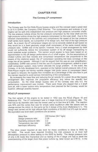
I've just come across this gem in A. McKenzie's "Axial compressor development at Derby".
Dr AA Griffith's solution for low speed surge margin was to bypass air from the LPC. The split compressor alone was not sufficient to alleviate the low speed off-design mismatching.

So it seems any performance gain as a bypass engine would be a bonus, but not the prime reason for the bypass.

Split compressors worked ok on the Olympus and J57. Perhaps their lower pressure ratios helped them to work without bypass: Olympus 201 10:1 and J57 12:1.
I don't believe any of them had VIGVs or bleed valves either.

Any thoughts?
 
CharleBarley,
I think your reading of McKenzie is not quite correct. If you had quoted the whole paragraph the context changes. It is worthwhile reading RRHT TS11 along with TS4. My mentor Geoff Wilde was in charge of the compressor aerodynamic design for the Conway. As he put it:
"After having designed the RA14 compressor and demonstrated the powerful effect of inter-stage bleed on off-design performance, the next engine, RB80, exploited this to the full by designing the compressors to have permanent inter-stage bleed combined with the idea of two compressors in series driven by independent turbines on separate shafts In the search for improved fuel economy[to extend range of the aircraft it was intended for], it was necessary to raise the pressure ratio and the turbine inlet temperature of the engine without increasing the velocity of the propulsive jet. this was necessary so that the propulsive efficiency of the engine in flight would be maintained or bettered. The permanent inter-stage bleed was the solution allowing the use of a 4-stage LP compressor giving a PR of 2.7:1 and eight-stage HP compressor of 4.4:1 enabling the overall engine the overall engine pressure ratio to be increased to 12:1 with substantially the same number of stages as the Avon turbojet [7.5:1].
If you read this in parallel with the McKenzie introduction to Chapter 5 the key statements are "Griffith was of the opinion, however, that a 2-shaft arrangement by itself would not sufficiently relieve the compressor system of its off design mismatching to avoid potential surge problems.... Although it can be argued that this was an over-simplification, nonetheless, Griffith was correct in that the use of a bypass arrangement, added to a twin-shaft compressor system, does further alleviate the surge problem...."
In case anyone thinks I have been selective in the Intro I have scanned it in (below).
Jim Boales once showed me the first concept for the Conway with calculations and sketch on the back of a foolscap envelope; the bypass was always a primary design parameter not a fortuitous byproduct of designing to avoid surge.
Don Eyre who, in Advanced Projects Dept, did a lot of work on what became the RB211 often chatted to me about AA Griffith who he 'drew' for.
Don wrote RRHT HS36 and I have copied the relevant bypass pages below.
I hope this clarifies where bypass came from.
 

Attachments

  • RRHT-TS11-McKenzie-p45-chapter5-intro.jpg
    RRHT-TS11-McKenzie-p45-chapter5-intro.jpg
    886.5 KB · Views: 237
  • RRHT-HS36-Don Eyre-bypass01.jpg
    RRHT-HS36-Don Eyre-bypass01.jpg
    1.1 MB · Views: 221
  • RRHT-HS36-Don Eyre-bypass02.jpg
    RRHT-HS36-Don Eyre-bypass02.jpg
    558.1 KB · Views: 204
  • RRHT-HS36-Don Eyre-bypass03.jpg
    RRHT-HS36-Don Eyre-bypass03.jpg
    865.3 KB · Views: 207
Great stuff. I have no excuse as I have TS4 and HS36. Thanks for focussing me on the relevant pages Tartle
 
One of the reasons for the relatively low bypass ratio used in the Conway was that the British aircraft designers were addicted to the idea of burying engines in the wings for large aircraft, such as the V bombers. Consequently, the engine installation imposed constraints of its own. The podded engine arrangement adopted in the US did not have these constraints.
 
That's right ... you can see the early schemes Don did for Griffith had much higher BPR, but there was no intention to bury them in the wing... there was much worry about drag of podded engines vs pressure recovery in intake ducts etc. An interesting survey of intake 'fashions' can be found here.
...and podded installations here.
 
To be fair, the R-R Conway did prove the viability of British aero-engine technology for 'podded' civil applications,
giving both the VC-10 & the big US jet airliners excellent 'hot & high' take off performance..

.. & paving the way for continued/ongoing R-R airliner turbofan popularity..

http://www.flightglobal.com/pdfarchive/view/1960/1960%20-%200077.html
 
You are quite right , JAW; in fact once the constraints of Victor and V.1000 wing installation was removed bpr went from 0.3 to 0.6. There was a further paper project... the Conway 7 which took bpr to 1.0 but this was superseded by the RB178 project which covered a lot of work on higher bpr... sort of Super Conway...by 1965 RR decided to fund a demonstrator, the RB178-14 at 2.3 bpr and shortly after this ran in '66 the VC10 for which it was intended was cancelled. At this time experimental work by NASA showed nacelle drag of high bpr was half that assumed by Europeans and so RR suddenly realised that higher bpr's were quite practicable and the project went to -51 of much higher bpr...6. The rest is history , maybe.
 

Similar threads

Back
Top Bottom