
You are using an out of date browser. It may not display this or other websites correctly.
You should upgrade or use an alternative browser.
You should upgrade or use an alternative browser.
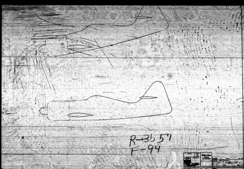
Blohm und Voss P.180
- Thread starter kiradog
- Start date
Hi Peter, although not an expert, I believe the rudder will be more consentual since its shape is reminiscent of some B&V designs. The wings seem more difficult...
Come on, lads!!! Start popping your advises.
Come on, lads!!! Start popping your advises.
Hi Peter
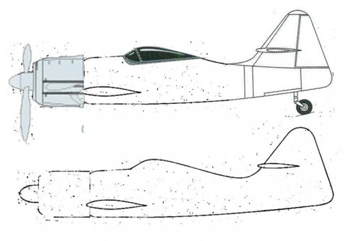
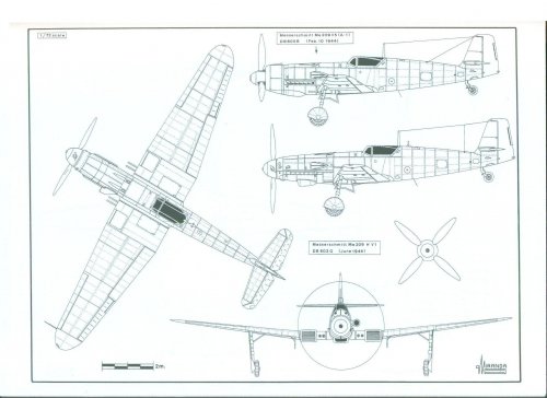
Wingspan 10,5 m.
Length 8,9 m.
Engine and propeller from an Fw 190.
Tailplane from B&V P.179
Wing from B&V P.178 (corrected to symmetric plan)
Canopy from B&V P.204
Camo from Fw 190 F
Role ground straffing
")
Wingspan 10,5 m.
Length 8,9 m.
Engine and propeller from an Fw 190.
Tailplane from B&V P.179
Wing from B&V P.178 (corrected to symmetric plan)
Canopy from B&V P.204
Camo from Fw 190 F
Role ground straffing
Attachments
- Joined
- 3 June 2006
- Messages
- 2,842
- Reaction score
- 2,543
Yes, as an concept to replace the ageing Junkers Ju 87 Stuka. In the real WW2, the Stuka had been largely replaced by ground-attack versions of the Focke-Wulf Fw 190 like the Fw 190 F.
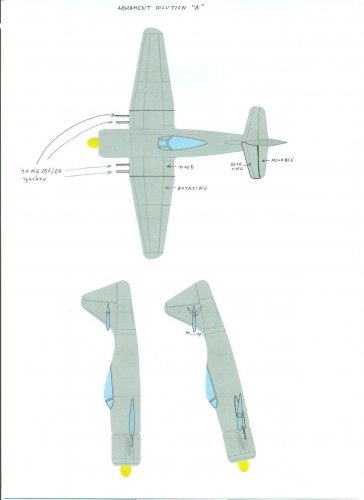
IMHO without any proof or source. the "variable incidence wing / rotating wing" on the Blohm und Voss P.180 can not carry heavy loads like bombs or PAK's. Maybe later on in this timeline unguided rockets might be installed on the wings.
That means just one bomb under the fuselage.
IMHO without any proof or source. the "variable incidence wing / rotating wing" on the Blohm und Voss P.180 can not carry heavy loads like bombs or PAK's. Maybe later on in this timeline unguided rockets might be installed on the wings.
That means just one bomb under the fuselage.
- Joined
- 11 March 2006
- Messages
- 8,608
- Reaction score
- 3,061
To me it seems strange, that it isn't a true mid wing concept. With a radial engine, the forward fuselage
probably was quite near to a circular cross section in the forward part and with the wing set lower, than
the middle (vertically) of the fuselage, there should be a gap at the junction, I think, maybe resulting in
aerodynamic problems, as placing a flexible or adaptable cover may be difficult. Rotating the wing probably
wouldn't be a big problem, due to the tubular main spar used in many B & V aircraft .
As Jemiba mentioned, this variable-incidence wing could well be a logical outgrowth or Richard Vogt's preference for tubular, often steel spars which often served as fuel tanks.
It's a corrollary to the variable-incidence wings used on some experimental carrier aircraft and flying boats to improve visibility and/or reduce landing gear length in the landing configuration (see, for example, http://www.secretprojects.co.uk/forum/index.php?topic=6577.0).
I don't see why that setup would necessarily limit the amount of bombs that could be carried or prevent the use of rocket projectiles, though a self-adjusting gun sight would be handy.
The obvious advantage, in this case, would be the ability to lower the nose on a bombing run to get a better view of the target. On a strafing run, the effect for fuselage-mounted guns would be the same as the downward-inclined guns used on some contemporary, especially Soviet, aircraft, in that the aircraft could maintain altitude but still bring the guns to bear.
The downside, other than increased structural weight, would be some handling quirks and definitely some loss of speed on the attack run due to the increased fuselage frontal area. Wing guns would also be problematic in the "skewed" configuration.
- Joined
- 11 March 2006
- Messages
- 8,608
- Reaction score
- 3,061
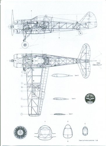
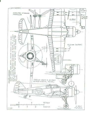
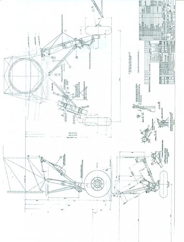
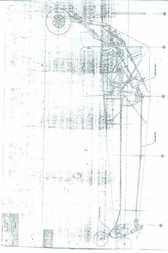
An interesting point will be the landing gear, I think. Either the wing has to be brought into a pre-defined postion, probably
negating some of it's positive effects, or the gear would have to be completely fuselage mounted, not that easy, although
the Swedish FFSV J-22 comes to my mind. But then, obstruction by the rotated wing would have to be ruled out.
negating some of it's positive effects, or the gear would have to be completely fuselage mounted, not that easy, although
the Swedish FFSV J-22 comes to my mind. But then, obstruction by the rotated wing would have to be ruled out.
- Joined
- 28 October 2006
- Messages
- 1,004
- Reaction score
- 98
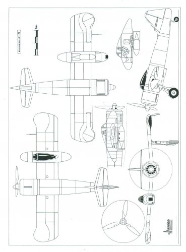
Made a little start. Cobbled together a patch-work side view, using bits from Justo's diagrams.
It's rough but it's started to show.
I realise there's a bit more smoothing out the joins but comments, suggestions and corrections are very welcome.
More soon
Peter
It's rough but it's started to show.
I realise there's a bit more smoothing out the joins but comments, suggestions and corrections are very welcome.
More soon
Peter
Attachments
- Joined
- 28 October 2006
- Messages
- 1,004
- Reaction score
- 98
- Joined
- 11 March 2006
- Messages
- 8,608
- Reaction score
- 3,061
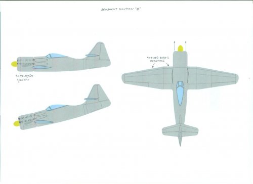
Seems logical to me, that the tailplane rotates, too.
A question still unanswered, I think, is the wing fuselage junction. There must a
gap between fuselage and wing to allow the rotating wing to clear the fuselage sides,
but I cannot imagine a suitable cover, as here it would have to cover quite an area
with quite a high elasticity.
A question still unanswered, I think, is the wing fuselage junction. There must a
gap between fuselage and wing to allow the rotating wing to clear the fuselage sides,
but I cannot imagine a suitable cover, as here it would have to cover quite an area
with quite a high elasticity.
Attachments
I would suggest a straight, chordwise break at the wingroot fairings which would remain fixed relative to the fuselage and only be aligned with the main wing in conventional, high speed mode but not during the attack run. And yes, the tailplane could be variable incidence as well, with or without a separate elevator, though I would tend to go with the separate elevator unless there are other B&V designs of the period with all-moving tailplanes.
- Joined
- 11 March 2006
- Messages
- 8,608
- Reaction score
- 3,061
Ah, yes, a good idea, although I somewhat would have expected such a layout to be recognisable even
in the very basic sketch, we've still yet seen.
About the tailplane, I think, it would rather be an increased range for trimming, than a completely new
construction. AFAIK, trimming was done this way for a several aircraft.
in the very basic sketch, we've still yet seen.
About the tailplane, I think, it would rather be an increased range for trimming, than a completely new
construction. AFAIK, trimming was done this way for a several aircraft.
theponja
ACCESS: Secret
- Joined
- 5 September 2007
- Messages
- 429
- Reaction score
- 38
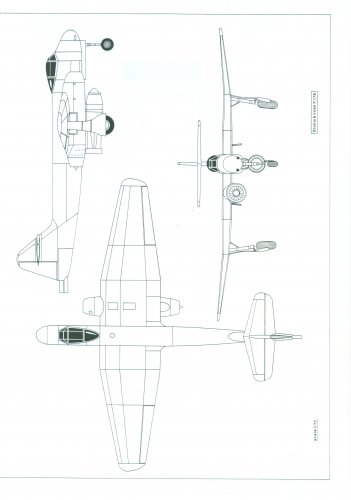
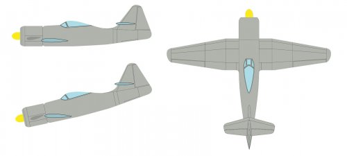
Flitzer said:A bit more progress.
Now done basic plan view. The fuselage seems a little fat.
Any suggestions, errors or modifications please?
Nice work Peter. I think the fuselage has to be "fat" because you need space for the rotation mechanism.
- Joined
- 28 October 2006
- Messages
- 1,004
- Reaction score
- 98
Fat it is then... .
I've been pondering...not always advisable I know...but if the wing rotates directly against the wing roots/fuselage side would there not be a need of some kind of rubbing area? Otherwise if the wing roots extended a little away from the fuselage sides, the wing could rotate without any problem, mechanism not-withstanding. See where pondering gets you....
Many thanks
P
.I've been pondering...not always advisable I know...but if the wing rotates directly against the wing roots/fuselage side would there not be a need of some kind of rubbing area? Otherwise if the wing roots extended a little away from the fuselage sides, the wing could rotate without any problem, mechanism not-withstanding. See where pondering gets you....
Many thanks
P
- Joined
- 28 October 2006
- Messages
- 1,004
- Reaction score
- 98
- Joined
- 11 March 2012
- Messages
- 3,016
- Reaction score
- 2,693
Fancy wing root fairings (e.g. Spitfire) can be eliminated if you simply make the fuselage sides flat (e.g. Sky raider) where the wings rotate (change incidence). As long as the intersection angle approaches 90 degrees, drag is negligible.
Also consider that wing-mounted under-carriage is still viable if you always land at the same wing setting. Same wing setting means consistent touch-down angle and simple under-carriage.
Also consider that wing-mounted under-carriage is still viable if you always land at the same wing setting. Same wing setting means consistent touch-down angle and simple under-carriage.
- Joined
- 28 October 2006
- Messages
- 1,004
- Reaction score
- 98
riggerrob said:Fancy wing root fairings (e.g. Spitfire) can be eliminated if you simply make the fuselage sides flat (e.g. Sky raider) where the wings rotate (change incidence). As long as the intersection angle approaches 90 degrees, drag is negligible.
Also consider that wing-mounted under-carriage is still viable if you always land at the same wing setting. Same wing setting means consistent touch-down angle and simple under-carriage.
Sorry its been a while, much longer than intended. Something like 'Writer's block, change of job and hours etc, have all taken their toll.
But another hours change at work has played into my hands, so I'll be back on a regular basis.
I'll get working on it again.
Peter
- Joined
- 28 October 2006
- Messages
- 1,004
- Reaction score
- 98
Wurger said:Hi Peter, remember this project? Can you please resume work on this B) ?
Back on it....just need to refresh my memory....
- Joined
- 28 October 2006
- Messages
- 1,004
- Reaction score
- 98

- Joined
- 11 March 2006
- Messages
- 8,608
- Reaction score
- 3,061
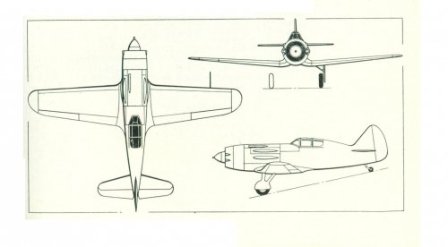
Swedish solution
The Wooksta!
ACCESS: Restricted
- Joined
- 13 July 2006
- Messages
- 20
- Reaction score
- 20
Bearing in mind the P.180 looks to be a lash of a set of P.178 wings, likely retaining the main gears, married to a modified P.179 fuselage, why would any sensible engineer move the u/c from the wing to the fuselage, especially an area already full of actuator equipment to move the wing?Indeed !
A fixed wingroot fairing, as proposed by cluttonfred (#20) maybe could
alleviate problems with the landing gear. Would result in a quite narrow
track width, but that was a problem of many aircraft then.
Other than some of the jet proposals, B&V always went for wide track so why make something more complex than it need be?
Similar threads
-
 Blohm & Voss outboard tail projects (origins and descendants)
- Started by negoshi8or
- Replies: 50
-

-
Blohm und Voss P.173.02 - Long range bomber project
- Started by kiradog
- Replies: 13
-
-
Blohm und Voss P.200 Transocean Seaplane Project
- Started by kiradog
- Replies: 20